I use estlcam exclusively and love the probe options using just aluminum tape. I am having a problem with the probe center of circle, but I think it’s just me. You have to flash to use it and any changes to the settings (calibrating) have to reflash but you can reflash back to CM if you want (I just haven’t needed to so I’ve not tried to flash back). My board is the version 2.4D board but I would ask support to qualify your using Estlcam as it is not their supported software.
Well for one, I could be partially to blame. I gave them a LONG list of things to fix and include in the software.
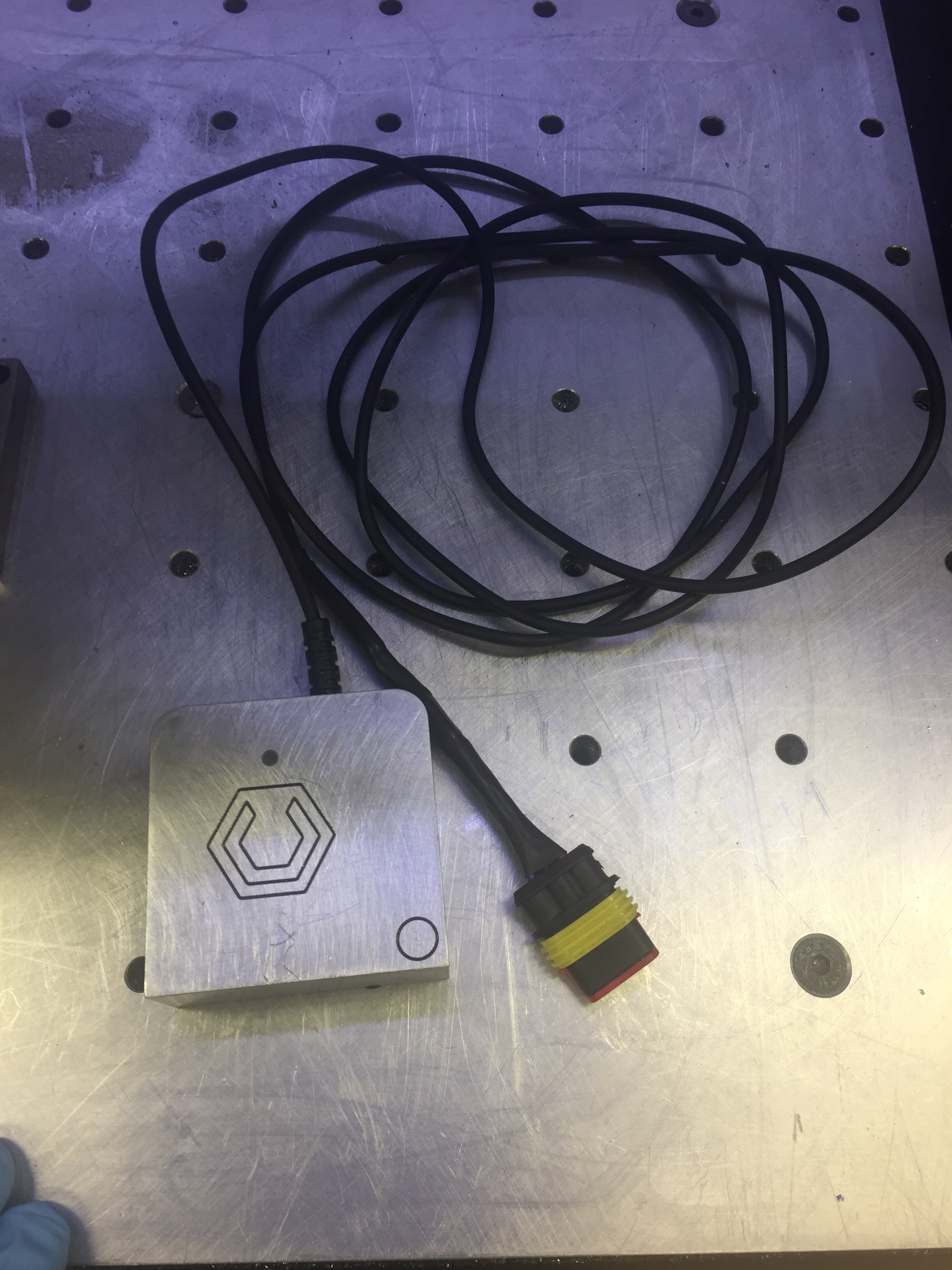
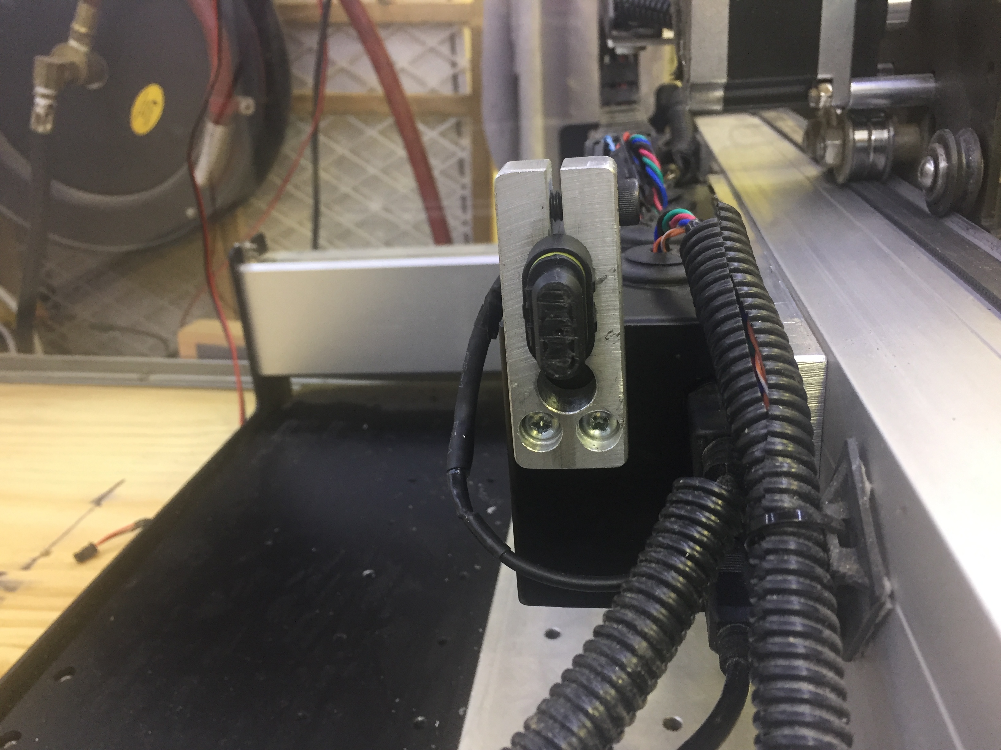
Here is something I’m 99% sure that they won’t include but was a MUST for me. The probe comes with eight (8) feet of wire (Probe and a ground clamp, 4 feet each). With the amount of metal I cut combined with the coolant, WD40 etc, I can’t have all this wire exposed. So today I installed a triple (silicone) sealed plug and installed a banana plug for the ground clip, so that I can remove the touch probe when not in use.
(The yellow thing in my hand is a plug that will keep the female plug clean and clear of chips.)
I believe people were thinking (hoping) they could use their own probe and input the dimensions of the probe in settings somewhere. In the version I have there are no settings for the probe that I can see…
The assumption/hope is the CM software will allow the individual user to make their own touch plate. Will V408 allow the user to input the deminsions of their own plate or does the software require the purchase of the Carbide version?
@RichCournoyer No blame here. Thank you for all your posts and mentoring here. Invaluable indeed. Could I ask you which connectors are those and where you got them?. I’ve been looking for banana plugs to see if I mod my Nomad to receive a probe. I already have the wiring done just need the connection.
Ebay. Search for 3 Pin Way Car Waterproof Electrical Connector Plug with Wire Cables (I wanted waterproof since I (a) cut a lot of metal, (b) use coolant and WD40.
Yes, but since it was not directly sent to me and because I am just a tester and not a Carbide3D developer/employee, I am not the best person to answer your question.
BUT I can comment on the Probe and 408 beta that I have been testing. Let me start with the fact that the Touch Probe has a circuit board inside of it, that I believe is the brain behind the macro. So having said that, hell no it (the macros) won’t work with a user’s made probe.
Thanks @Tito for correcting my typo. You got my drift with regard to the question, and as confirmed by @Luke, there’s no place one can specify the offset dimensions of one’s probe.
Not providing any support for an alternative probe setup in v4.08 is a non-starter for me, and I hope Carbide realizes that this is a very necessary feature they need to bolt in for the v4.09 update.
I’ve been watching this unfold, and my suspicions have been confirmed.
Again, I suspect it comes down to balancing reliability over customizability — it would be nice if we could do a perfectly customizable product which would be absolutely reliable no matter when one did with it, but that’s just not possible.
I suspect someone will document the dimensions of the probe early on, then it should just be matter of working up a way to cope with the resultant offset.
@RichCournoyer Thanks Rich. I appreciate the information. I saw a circuit board in an earlier message but didn’t give it too much thought until now. How is the probe connected to the controller?
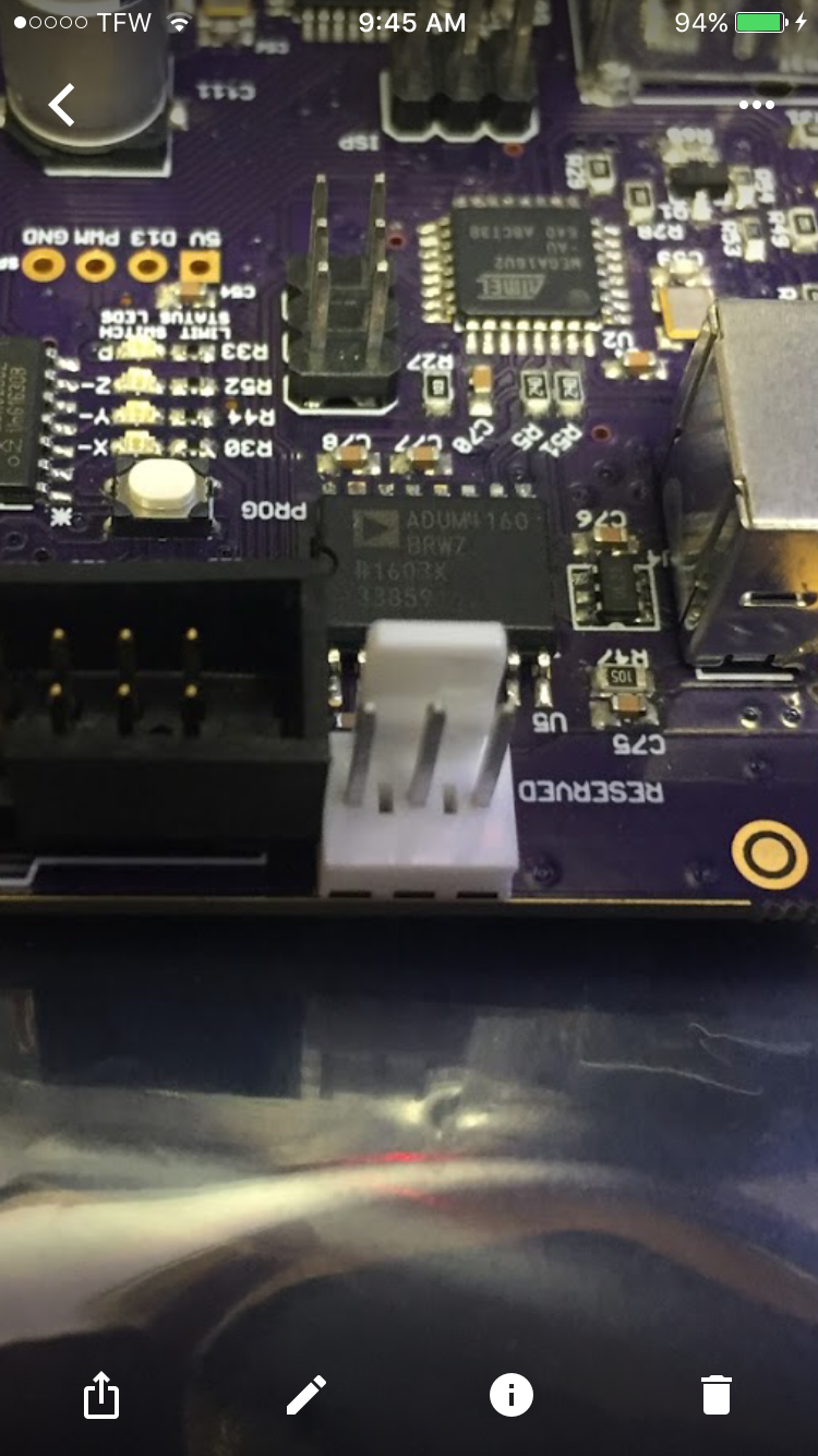
I know OF two methods to attach touch probe to the controller board. The first easiest method is to attach it to the small three pin connector that is presently marked reserved (see photo).
If your board does not have a three pin connector, the touch probe comes with a pigtail, and that gets attached to the two probe connection near the axis limit switch connector and a third wire needs to be connected a 5V pin.