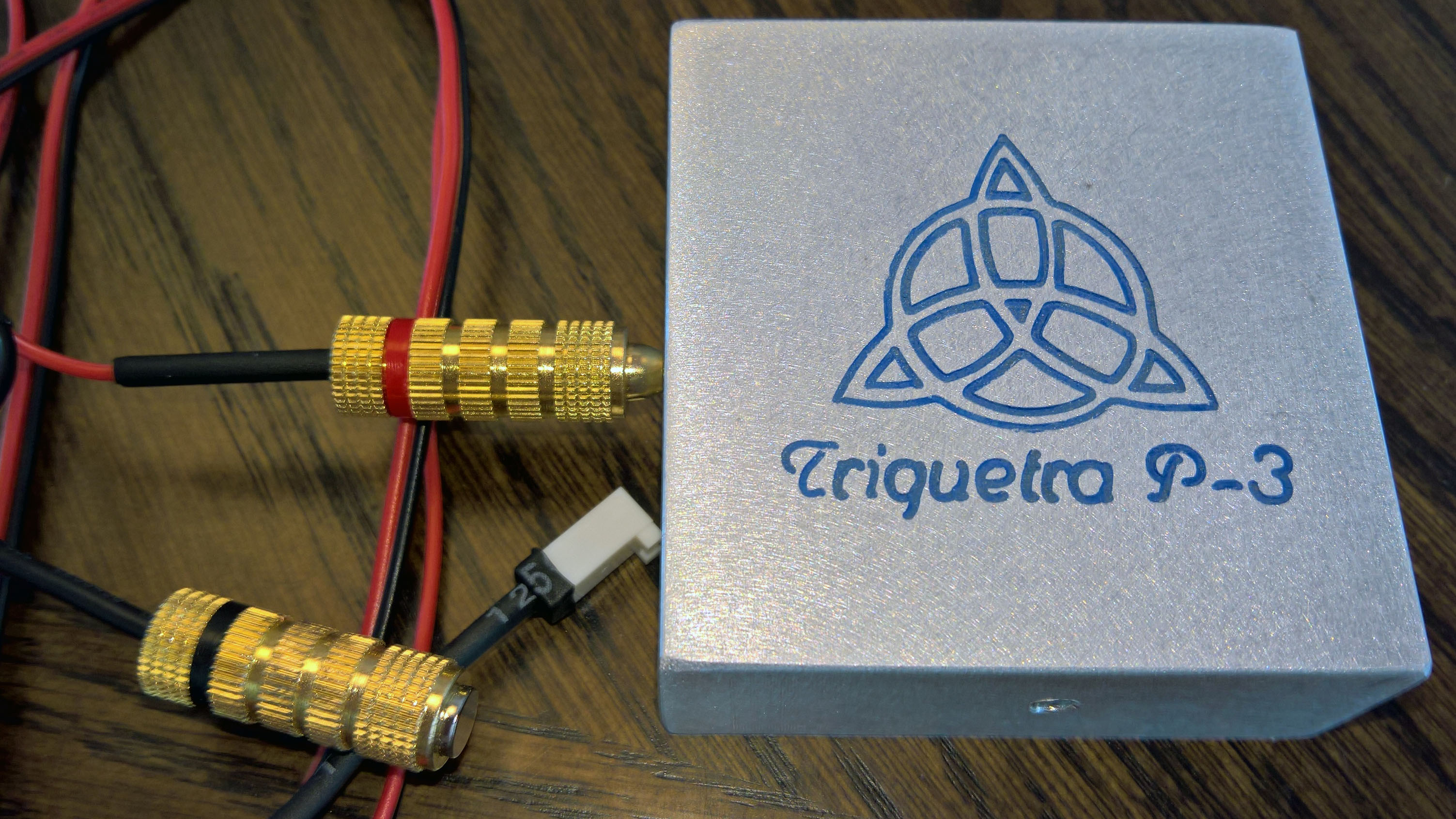
I recently purchased a Triquetra touch plate for use with my Shapeoko 3. I know that several people in the community are using one but I was having issues finding a good guide on how to set it up - the information was scattered across multiple posts. So, I thought I’d put one together in the hope that it will help someone in the future. Since the Triquetra touch plate is fairly generic in nature these instructions will most likely work for similar touch plates as well - it probably works with the Nomad too.
The purpose of this guide is to show how I wired the Triquetra plate to the Shapeoko controller board. Here is what I used to get started:
Materials:
- Triquetra 3-Axis Touch Plate
- 22AWG Wire 2 Conductor (this should be long enough to reach anywhere you’d need it on the Shapeoko bed)
- 2qty Closed Screw Type Banana Plugs
- .25” Neodymium Magnet
- Molex 2 Position Connector Housing
- 2qty Molex Connector Terminals – Female
- Misc. Heat Shrink Tubes
Tools:
- 22AWG Wire Stripper
- Soldering Iron and Solder
- Molex Style Micro Crimper
- Heat Gun
The gauge of wire that is in the cable included with the Triquetra probe is too large to crimp with the Molex terminals. So, I replaced this with my own cable. This also allowed me to use a better quality banana plug (I had issues with the original banana plug in that it broke after removing it from the block a few times).
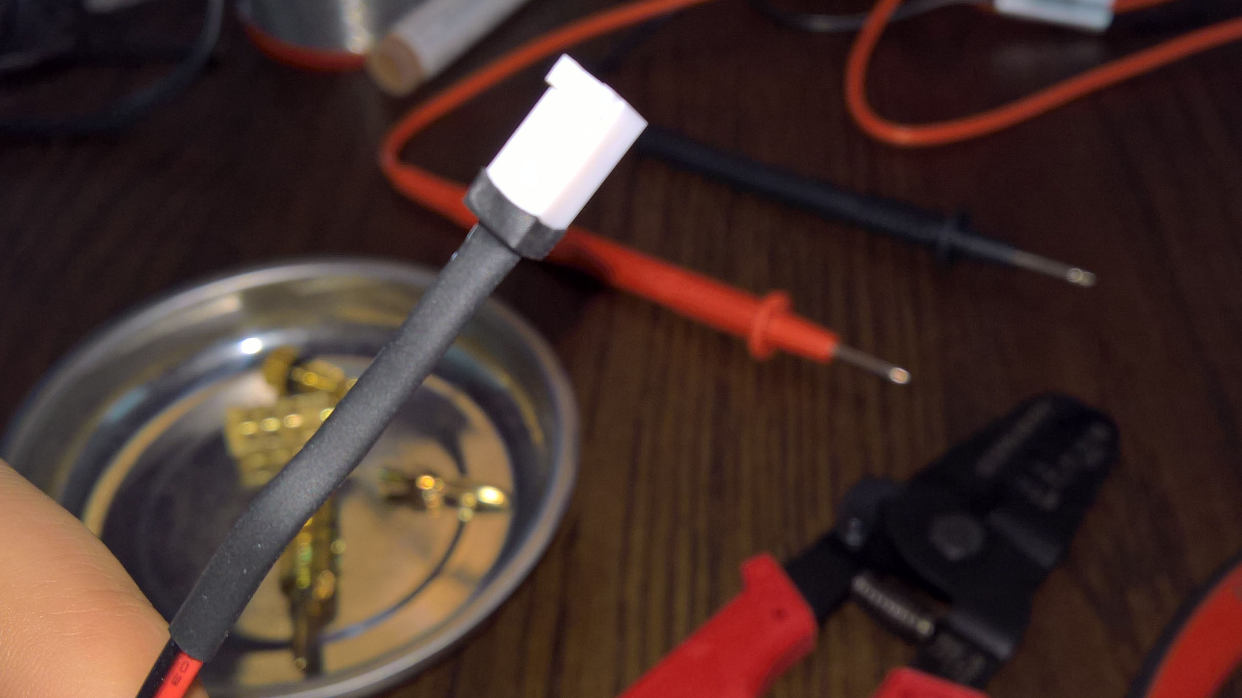
I started by stripping a small amount off of each wire:
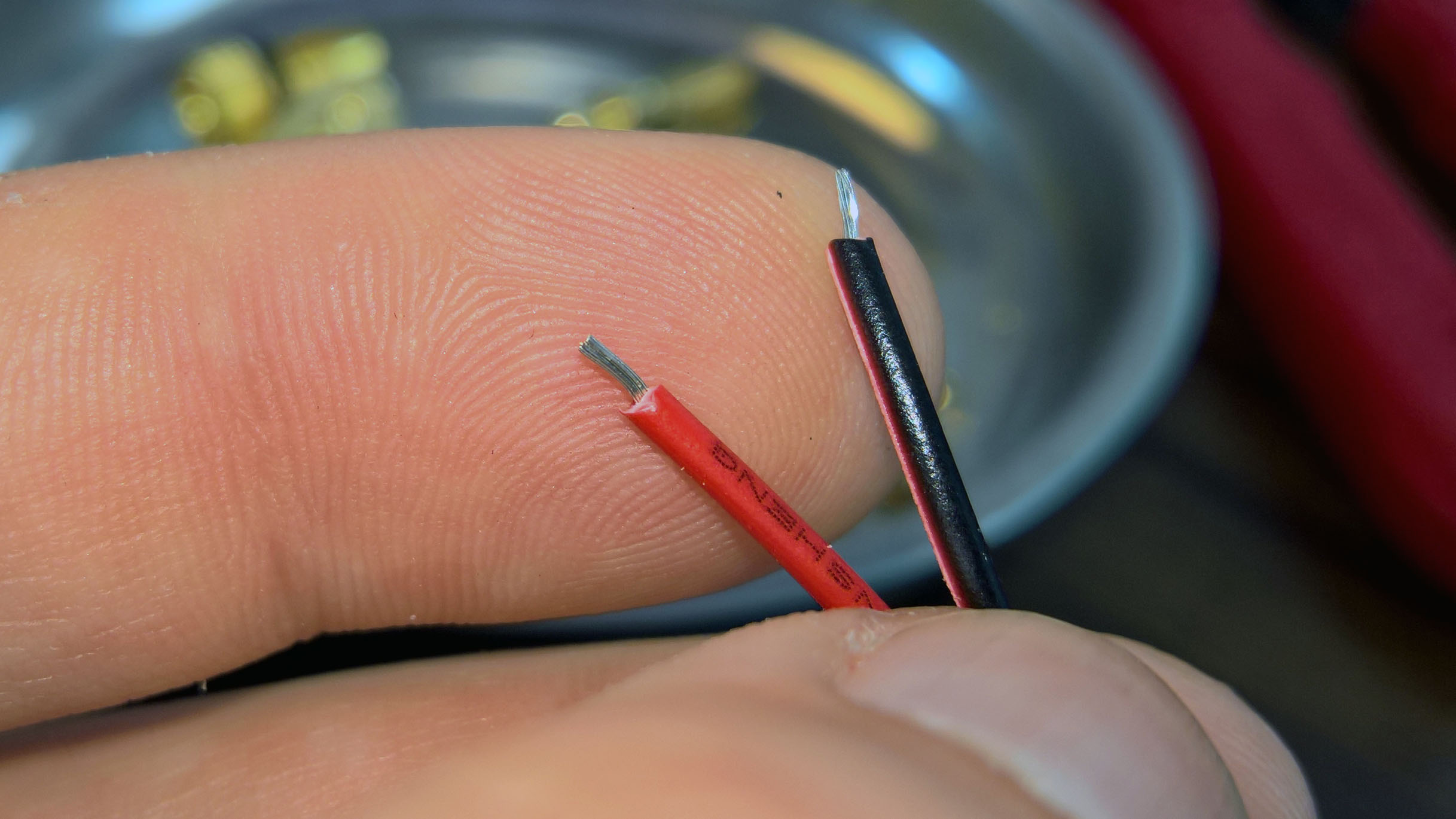
I then crimped the terminals onto the wire using a micro crimper:
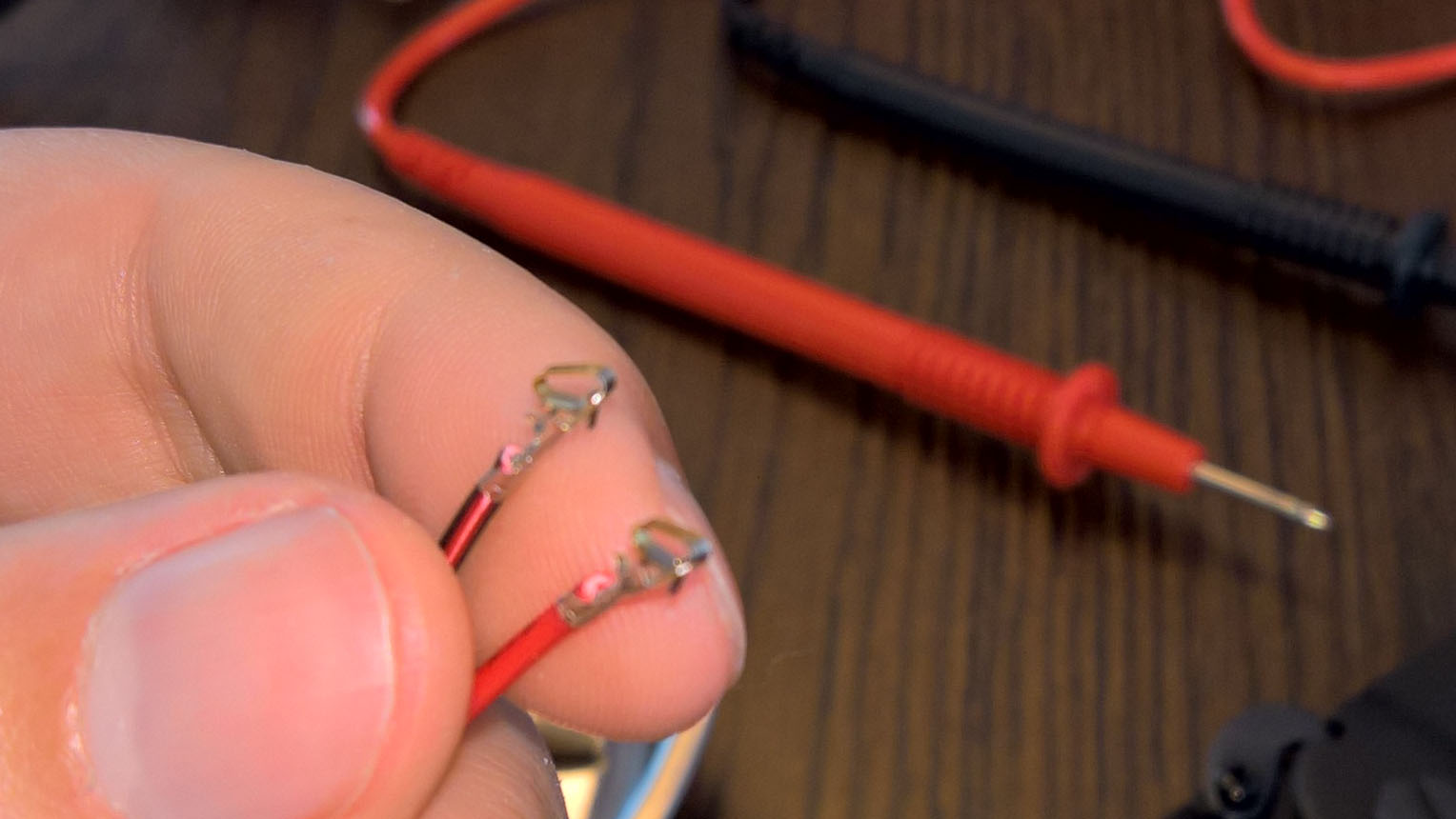
The red wire in this tutorial carries the low-voltage while the black wire is for ground. The red wire should go to the touch plate and the black wire should go to the endmill. Insert the terminals into the connector housing as shown:
Note: newer versions of the controller board have a 3-pin header that is marked “Reserved” that is used for the Carbide 3D Touch Plate. This header can be used to connect the Triquetra probe. However, the Triquetra probe does not use the middle pin (red wire on the Carbide 3D Touch Plate). If you’d rather use the 3-pin header you can order a 3-pin housing instead.
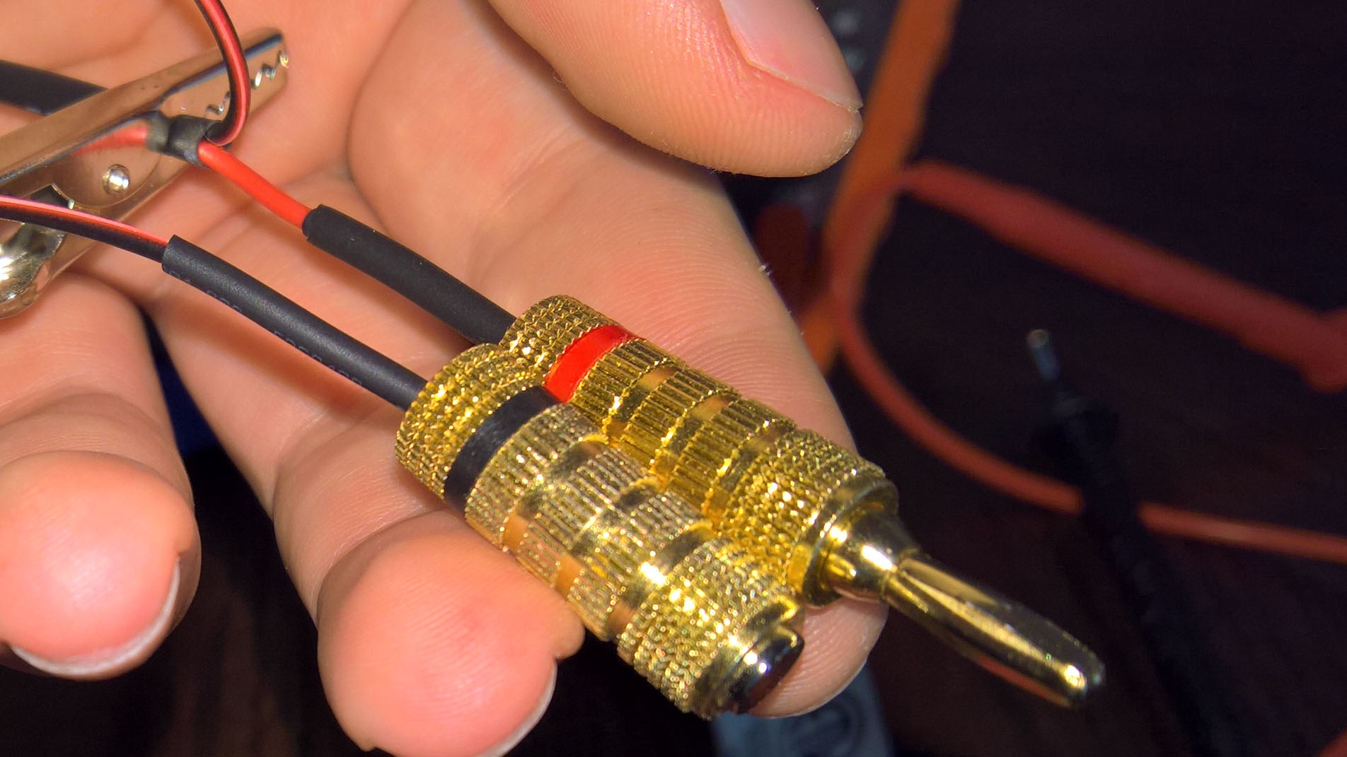
For the ground connector, I removed the banana plug post from the connector and inserted a .25” neodymium magnet into the hole. Depending on your banana plug you may need to widen the hole to accept the magnet. Or, alternately, you may need some epoxy to hold the magnet in place. A friction fit was enough in my case.
The banana plug connectors are typically used with larger gauge speaker wire. So, in order to help better secure the wire in the connector I used a small amount of solder to connect the wire to the connector housing. I also used some heat shrink tubing to enlarge the wire sheathing for a snugger fit in the connector. The end results should look like this:
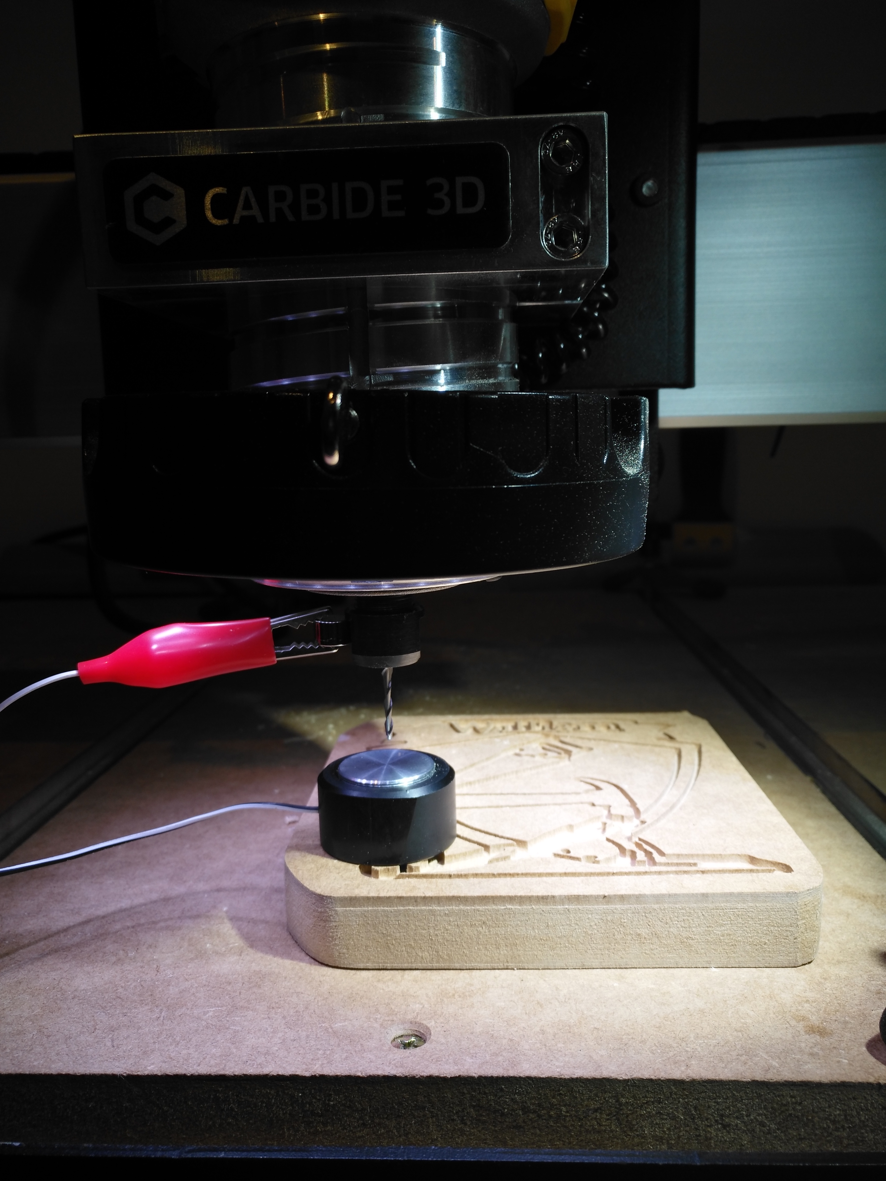
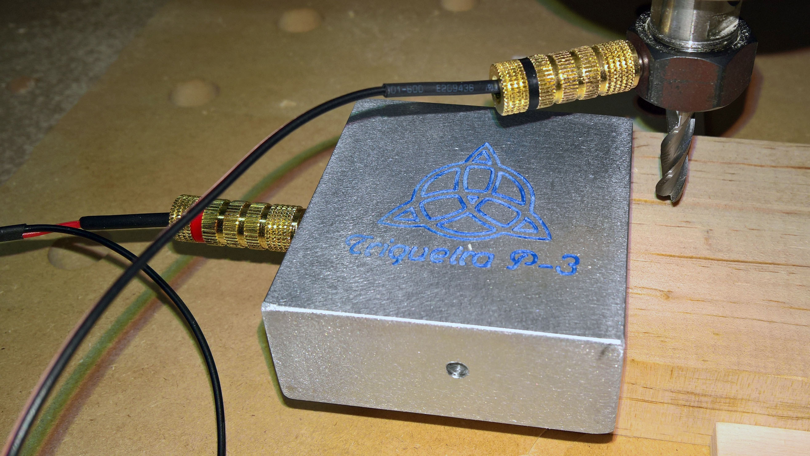
At this point you should be ready to connect the touch plate and test. You can connect the Molex connector to the board using the 2-pin “probe” header that is next to the Z-Limit header:

Here is the end result:
Hope that helps!