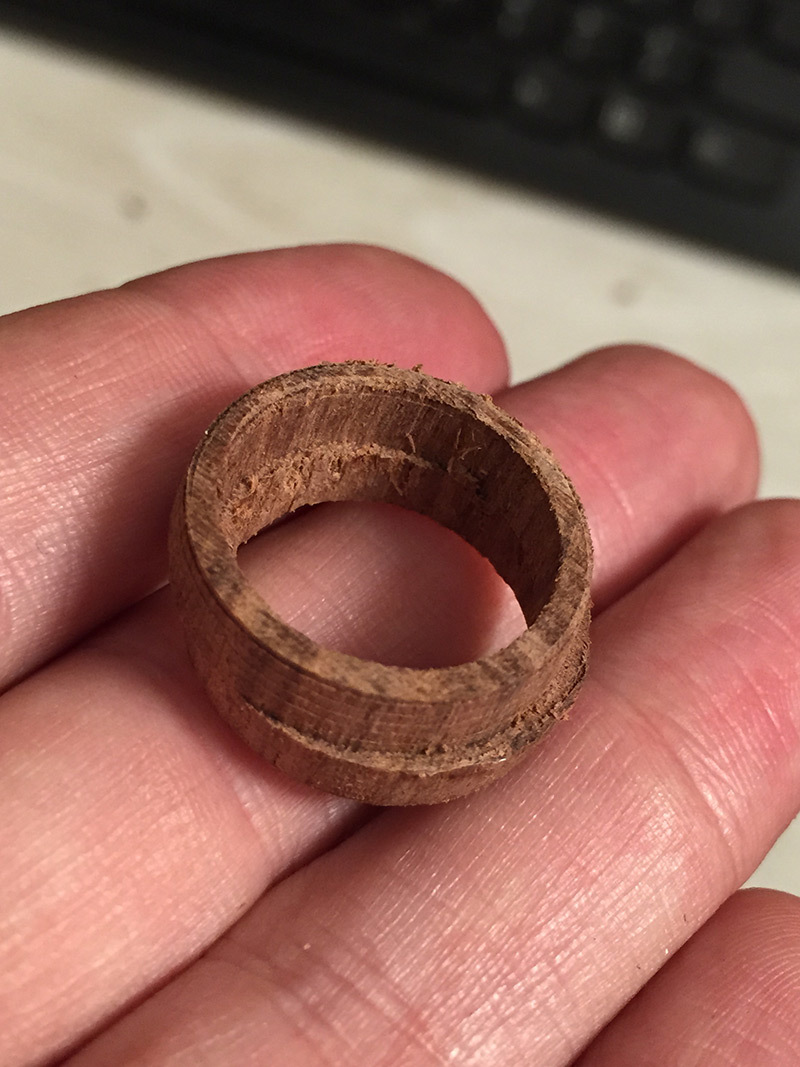
I thought I’d try to do a two-sided carve. I though I’d cut a ring from some nice hardwood. Since I have no flip-jig, my idea was this: create a ring model with a nearly filled center, bolt it down through the center, and use that as my reference point. I’d then use a retract height that would pass over the bolt, and exclude the center from machining for good measure.
I was going to run the job, unbolt the stock, flip it, and run the job again using the same zero point.
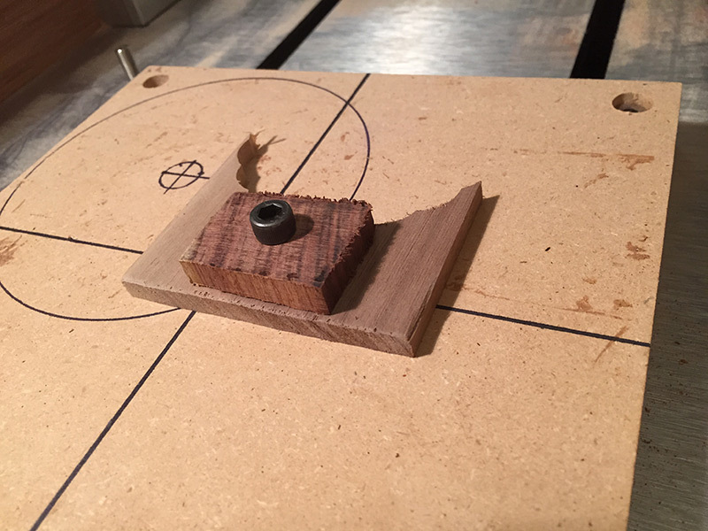
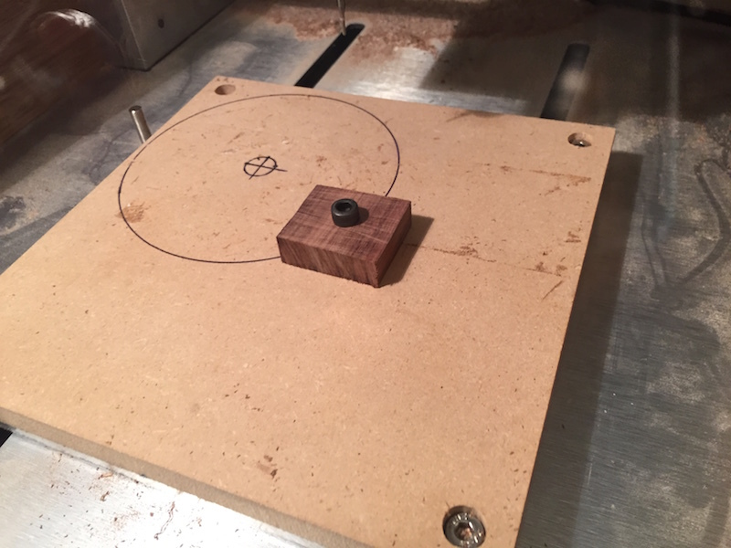
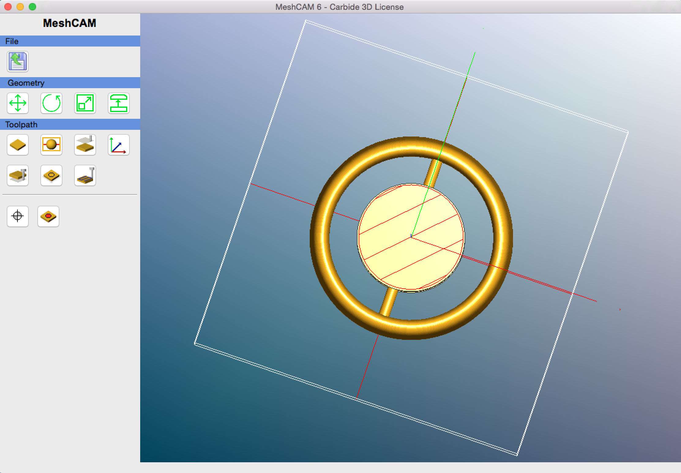
My bolt head is 10mm in diameter, and the core I designed into the ring is 11mm in diameter. Here’s the physical setup.
When I ran the job, it immediately started trying to surface the center core (which I thought would be excluded), and ground directly into the bolt head. I aborted as quickly as possible, so I don’t think much damage was done.
Still, I’m not sure where my thinking is wrong. Shouldn’t the exclusion be a full 3d exclusion?
It’s hard to see in your screenshot, but it kind of looks like there’s an itty bitty X,Y, and Z next to those axes centered at the top of your center disk. So it may be that you’ve defined the zero to be the middle of the center disk.
When you zeroed the nomad, did you also zero at the center of the stock or did you zero at the front left corner of the stock as usual?
If your Meshcam zero is in the center of the stock and the machine zero is at the front left, all the cutting would be offset by half the size of the stock forward and left, and when the Nomad tries to mill the back right corner of your design, that would put the endmill square on the bolt.
Hi kjl,
No, I confirmed that the zero point is at the center top of the stock in MeshCam, and on in Carbide Motion I was pretty careful to zero to the exact center of the bolt at the height of the stock.
I’ve done a fair number of things where I’ve used the center point of a piece as my zero point without any problems. This is the first time I’ve tried to exclude around that center point, though.
sjg,
Id really like to see this come out, there must be something somewhere a little off.
First, to simplify things, I would suggest opening your part in meshcam as a 3 axis part, since its going to be the same job for both sides. Set your max cut depth to just over half the depth of the ring.
After generating the toolpath, use the “Simulate Toolpath” to preveiw the cutting path.
Lastly, im sure you did, but make sure when you Zero out the X Y Z in carbide motion that you also click zero and the fields say “0” .Again, im sure you did, but double check.
Sometimes I run an air cut or a test in the MDF spoil board when experimenting with a new approach.
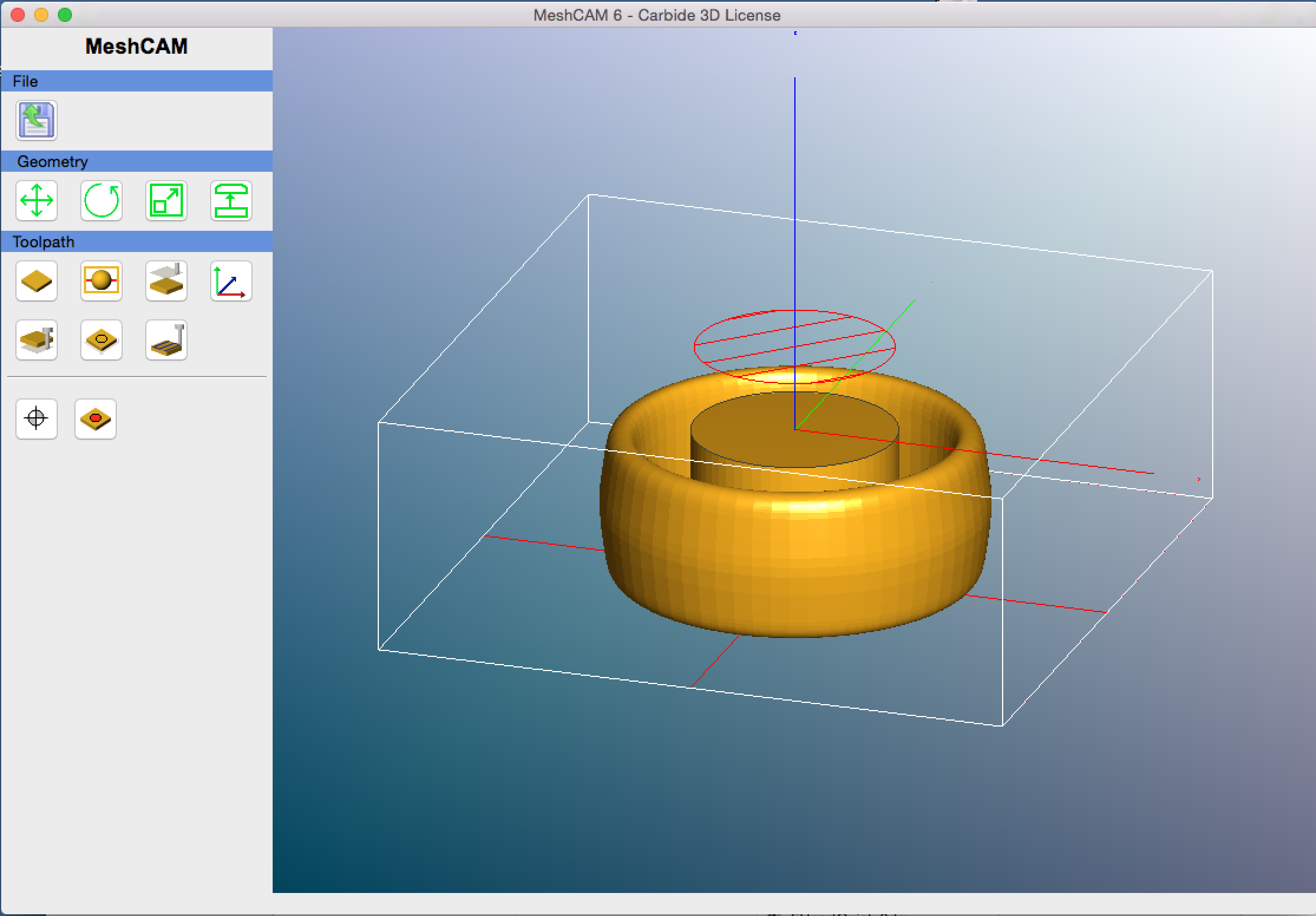
sjg, it looks to me like your MeshCAM origin Z is on the top face of the geometry, and not on top fact of the stock. MeshCAM draws the exclusion areas on the top face of the stock. But that should be safe–if you zero your cutter on the top face of the stock the toolpaths should be offset upwards from what you expect.
One thing you might try is to check Don’t Machine Top of Stock and see if that makes a difference.
A more likely route is to try increasing the size of the exlusion circle to fully enclose the cylinder you have modeled at the axis. As it is, the perimeter of the cylinder is fair game for machining since it peeks out around the exlusion zone. I’ll need to do some experimenting when I have a little time, because I don’t remember if the exclusion zone pertains to the cutter axis or cutter perimeter. MeshCAM might be bringing the cutter axis to the edge of the exclusion zone becuase it “sees” the edge of the central cylinder.
You can rotate and zoom the toolpath accepting screen and preview where the tool will be moving. It defaults to showing the rapid moves as well as the cutting moves. But the rapid moves should be up at the level you define.
(oops, I see Apollo was typing at the same time I was composing. Fortunately I seem not to have contradicted anything he said… )
Randy called it – I set my zero to the geometry, not to the stock! I would have sworn I’d checked that twice, but when I look at the file now, I clearly didn’t.
I think Apollo’s advice to try an “air cut” is a good one. It turns out I would have saved myself a cutter. I should probably go for softer bolts too
And dr_g, I have to admit I hadn’t thought too much about the aligning of my supports. I have marks so I know the rough orientation, but it might not be good enough for the tiny supports I designed in.
So, since it does turn out that I ruined my one remaining .0625" ball cutter, I just placed an order for three more. While waiting for those to arrive, I’ll play around with an end mill and some Renshape, and see if I can work out some of the details.
Another revelation from last-night’s work. I never understood why MeshCam makes it so hard to position the geometry at the bottom of the stock (every time you change the bottom Z-position, it changes the stock height, and you have to calculate and fill in everything by hand).
Now I see that, especially for something like this project, I actually need my geometry to be centered in the stock.
Probably this is obvious to everyone else in the world, but it had escaped me until now.
Samuel, with a pre-existing piece of stock as yours, after you enter the dimensions check “lock stock”. It still defaults to keeping the geometry centered, but you can uncheck an axis’ “centered” box and tweak a margin and MC will adjust the opposite margin given the fixed stock size…You can even enter a negative margin that way which on occasion is useful.
dr_g, it is a little hard to do precision support positioning. On really irregular pieces I keep a notepad handy and place one support at a time. I keep track of the Z position and rotate the geometry around after I have placed the support. If it is in the wrong height, I erase it and redo. I repeat this for all the supports and end up with a whole list I can add.
Oh, and one more thing. For your situation, Samuel, you don’t need to model the central cylinder, just the crossbar. Then use the exclusion zone centered on the origin as if the cylinder was there, and MC won’t do all the extra machining of the cylinder, just the ring itself and the parts of the crossbar that are outside the exlusion circle. I did a little playing with that last night but unfortuantely am not at that computer so I could take screenshots.
I also confirmed by doing that, that where there is geometry under the exclusion zone, MC will take the cutter axis to the edge of the exclusion zone. So you need to keep in mind the cutter radius when making an exclusion zone overlaying geometry.
It’s not wisdom, just experience. And you know what is said about experience–it’s what you earn when you do things wrong the first time. So you can imagine how much scrap I’ve generated over the years…
Randy
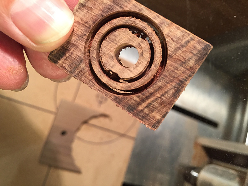
Well, so that all worked… sort of. Progress, anyway!
Now I just need to up my flip-jig game. I had thought that bolting stock directly to the table would be fairly precise, but I did notice a lot more play in the position than I expected. It’s partly because the mounting hole I drilled in the stock is imprecise, but even just experimentally the bolt (even under some tension) has a bit of play in it.
So here’s how things turned out. A few notes:
Using Randy’s exclude area trick instead of modeling the center column works fine.
dr_g is right, and my supports were not aligned very well. But there were bigger alignment problems.
I’m using an end mill, when this really calls for a ball-end.
The Nomad auto settings for hardwood are a little aggressive for this smaller 1mm end-mill, but when I adjust things it does a very good job on this ironwood.

 )
)