I finally decided to give this a test. I set up the wiring correctly.
At the MDI interface I typed in
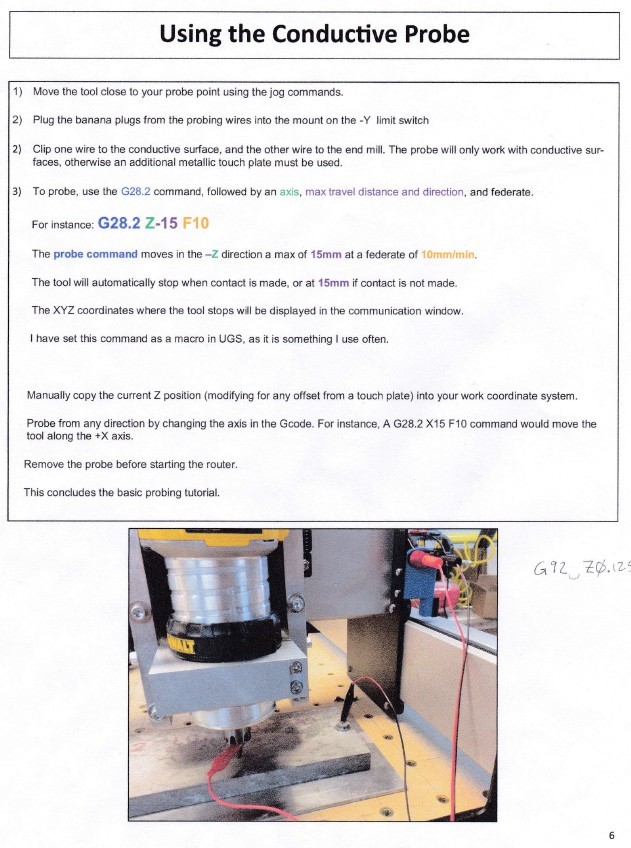
G28.2 Z-15 F10
When I hit enter, the Shapeoko did a home cycle, that’s all.
What went wrong? (There is a space between the 2 & Z and the 5 & F)
Also, just in case this works well someday, what’s the hot setup? I use wood most all the time, so I looking for something like a coupon that is precisely 0.1" thick and has a easy place to attach the alligator clip. Anyone have any suggestions?
So far, the help I get from this forum is just fantastic!!!
I think you are using the incorrect command. It should be G38 not G28
Probe using the G38.2 command
Z: G38.2 z-15 f20
(probe 15mm down using speed 20mm/min)
X: G38.2 x15 f20
(probe 15mm right using speed 20mm/min)
Y: G38.2 Y15 f20
(probe 15mm right using speed 20mm/min)
After each probe you need to set the position either with G92 or with the typical G10
Examples:
G10 P1 L20 Z0
you can also enter offsets if it’s something you are touching that has an offset:
(If you use offsets you can account for the thickness of your center finder or other probe surface. A simple .125 thick aluminum plate works surprisingly well, you just have to enter the offset when you zero.
Unfortunately they have not built in the correct macros or interface to make it easier yet. One more reason I’m writing my own program.
G92 X0 Y0 Z0 (if the endmill is at the desired origin)
G92 X0 Y0 Z3.175 (if the Z-height of the tip of the endmill has been set off the worksurface using a 3.175mm Alum Plate (.125") the current unit system is metric)
G92 X0 Y0 Z-6.35 (if the Z-height of the tip of the endmill is currently set at the worksurface and one has stock material mounted which one wants to leave a quarter inch of material uncut (at Z0 and lower) and the current unit system is metric)
Hello All, I’ve been struggling with this 2.4 board revision to get probing working correctly. This is the third board support has sent me where probing does not work correctly.
With it connected $6=0 Carbide Motion gives me Probing Cycle Failed. $6=1 probing works, but the probe needs to maintain contact with the spindle. Using G38.2 Z-15 F10 as the command.
Here is the output of these commands, with probing not working, (not connected, awaiting contact)
$6=0 ok $G [G38.2 G54 G17 G21 G90 G94 M0 M5 M9 T0 F10. S0.] ok G38.2 Z-15 F10 ALARM: Probe fail [Reset to continue]
So here is the output of these commands, with probing working but constant contact with the spindle must be maintained. $6=1 ok $G [G38.2 G54 G17 G21 G90 G94 M0 M5 M9 T0 F1. S0.] ok G38.2 Z-15 F10 [PRB:0.000,0.000,-4.600:1] ok
Any help getting this working correctly would be nice.
I also have the 2.4 board, but have no problem probing (even with the original board that came with the machine), but I do not use the same commands that you use because I ALWAYS got an error.
Actually I always had difficulty using the commands that are listed (Similar to your) and somehow, somewhere on some forum I found this information about 8 months ago that helped me (after hours of searching)
First I HOME my machine, and CLEAR any offsets. Next, I rapid over to my part, (I usually like to set my Z first) and stop the cutter about 1/4 (6mm) above the area I want to probe for my Z. I then look at the Z position on the left side of my computer screen. Let’s say it says -46.00 mm. I then type
G38.2 Z-56 F15 (The number -56 is not critical as long as it is great than the distance to the part less the present position)
The Z will then travel down to the part and stop
If I put a number that is too small to touch the part, say -50mm, it will travel down 4mm ( -50mm -46mm = -4mm) and then I will get error Alarm Probe Cycle Fail (because the probe did not touch the part).
I then probe the X and Y making sure that the number that I type after the G38.2 command (X or Y direction) is greater than the distance to the part.
Let me know if you have any questions. I have a Probing Video on my YouTube channel that also my help (Search RichardCournoyer of Shapeoko Probing)
you should set it to $6=0
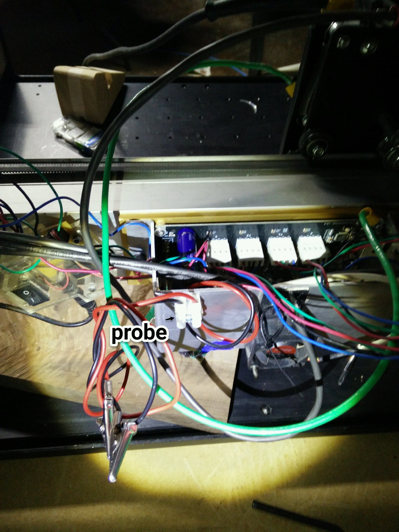
Your issue… More then likely is you are crossing the wires.
You need the GROUND wire to be in the spindle!!!
And the trigger wire to be on the plate you are probing toward.
Because the spindle is already probably grounded, adding the trigger wire to it probably automatically triggers the probe.
Swap the wires and let us know the behavior.
the circuit board is grounded to the railing though.
Test it with the VOM and you will see that the ground on the circuit board is connected to the ground on the rails of the machine.
It’s not the house ground it’s the circuit board circuit that matters.
@RichCournoyer bCNC, It’s just a front end with more features than Carbide Motion. If I use Carbide Motion the same thing happens.
Update: Just updated to Grbl 0.9j and still get the same issue.
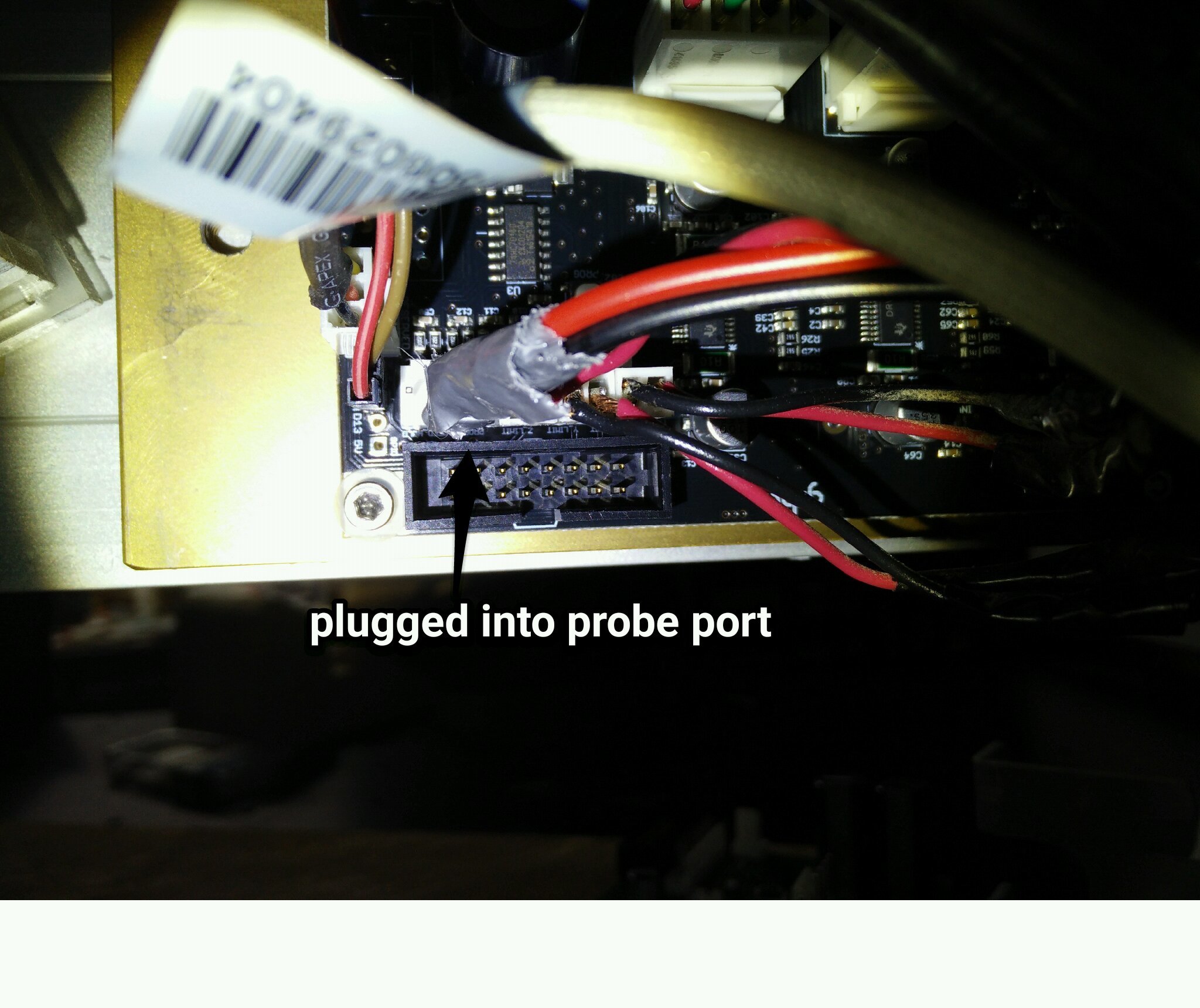
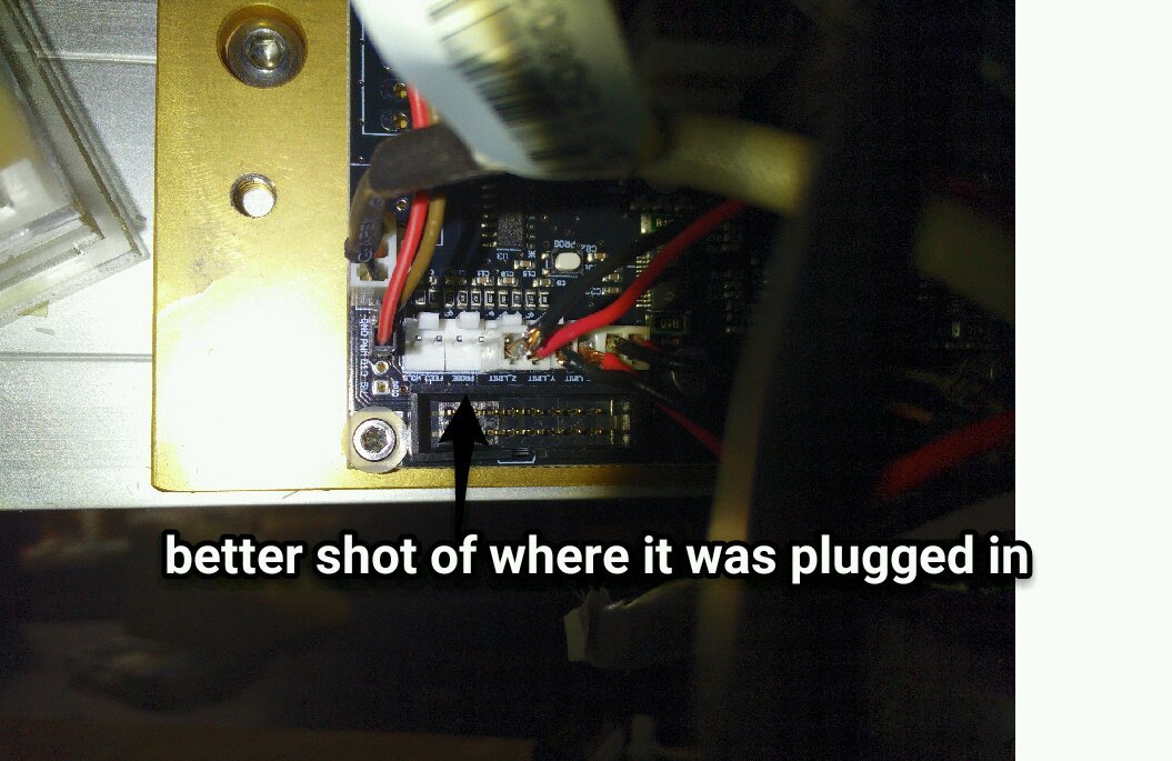
Also made a new locking socket .100 polarized connector to attach to the Carbid3D board. Even if the wires are not connected to the board via the 2 pin socket probing fails.
Does the machine move at all during the probe or not? If the machine does not move it sounds like the internal pull up resistor is not working on the probe pin. In theory you could add an external resistor to that pin and 5V rail and it would work.\But I’m making assumptions, one would have to do some experimentation and know exactly what is going on to know for certain. Based on your screen the feed is not what you need to increase it’s the Z depth. you have -10 or something like that in there it’s hard to see exactly. the Z depth determines how far it should probe before giving an error.
Thanks for the pictures, but I’m not sure that you are using a proper connector, and thus getting a good good connection at the probe pins which could be part or all of the problem. Also Roger has a good question, can you address it?