Does anyone have experience using their SO3 with a two-sided project and running multiple tool paths? Since the SO post processor does not support multiple tool paths to a single job file I want to approach this project in the most logical way. ( which will be my first full SO3 based job)
The two-sided project does not have any elements which are carving through the boards but I am placing items and require them to be where I expect them… obviously ;).
I am reading through the two-sided machining notes on Vectrics website now and I’ll run a simple test prior to running this full job, just to make sure I fully understand the process of setup and material flipping.
I guess I am just looking to see if there are some SO3 members that have used this feature of VCarve that have some experience to share on something that might not have been expected? ( I will probably post my job file here and on Vectric’s forums prior to running it just to see if experienced eyes catch something that might be an issue )
Basically I put two 1/4" holes into my program spaced exactly on centerline for sides 1 and 2. I then ran the program and drilled just these two holes into my waste board. I aligned my stock as best I could to these two holes and ran the same two holes. Flipped it over and used 1/4" steel dowel to align and clamped it down. Then ran the same two holes on the opposite side. After that I ran all of side 1, then flipped and ran all of side 2. Worked out great!
I basically did the same thing as Dan Nelson said, but I first secured my piece to my wasteboard using screws. I set the 0 for the project to the center of the piece. As part of the toolpaths, I drill two holes (lined on the center of the vertical axis or the horizontal axis, depending upon how I set up the two sides in Vcarve). I then put screws in those holes. When I flip the piece, I screw into the same holes in the material and waste board, and then cut the second side.
I basically have two sets of gcode – one for each side.
So when working two-sided projects it sounds like it might be best to set my X/Y datum position to the center of the job?
I ran a test tonight not using the center ( and prior to really absorbing what you guys were saying ) and I realized a few things along the way with the test. The first thing that was clear AFTER I ran this test is that using one of the corners of the job for the XY datum point will lead to issues with elements on the reverse side aligning to the dimensions as I programmed them in VCarve… *This is because I oversize all my blanks to allow for trimming in the shop and now that I have a SO3, it is also because I run my screws on this area that is on the outside of my final project size. So once my oversized material blank is on the SO3 table, I just move my zero point in off the edge by enough to make sure I can run screws… all my blanks are typically at least 1" larger in width and length so eyeballing this is accurate enough… until I get into running two-sided projects apparently.
I was thinking that maybe if I did use the corners that I would have to reverse the corners for the flip. In other words… if side A is set off the TOP RIGHT corner then side B should be set off the BOTTOM RIGHT corner… ? I have 1/4 holes already set into my waste board that I place dowels into for placing my material on the machine so I know its squared up to the XY axis travel of the machine. I am not sure if I am being clear enough on how I planned this out so I’ll go take some pictures of how I just ran my test. I have to re-run that test anyway making the switch to the XY datum corners to test my thought process anyway…
As I just went into VCP to attempt and rework this test with the two different XY datums point I realized you can’t do that unless you make two completely different job files… So I suppose it is necessary to use the center to set up a two-sided project where elements on the two sides are required to fall in alignment with the parameters I have set up in VCP
huh? You lost me there on the flipped edge/corner? SO you are saying that my original test method of using a corner registration for XY DATUM is best? But I suppose then I have to EITHER load a perfectly milled blank that equals my final size requirements OR I need to do some layout to find out exactly where to place my corner registration on my OVERSIZED board.
Again, I am not sure I am explaining all this in the most logical way. I am still trying to absorb this new way of thinking about my jobs… the Carvewright machine basically made CNC almost idiot proof… lol - perfect for me.
As I am trying to wrap my head around how to make sure I get these types of jobs right I think maybe a combo of the two methods is best…
Here is my next test routine.
My job dimensions are 8" X and 14" Y. I am going to use the CENTER XY Datum point though for this test.
I will STILL use the edge for material registration on the machine- This is because I already placed those 1/4 holes for dowels in the waste board and I know they are square to the machine travel.
My material blanks is 9-7/8" X and much longer on the Y… it’s the X that I am most concerned about based on how I set up my job though. But I will use a guide that is screwed to the table for registering one of the Y edges
SO - I think the only thing I need to be accurate with here is finding the CENTER of my blank on the X and then make sure that the machine ZERO is right on it… then, when I flip, my edge registration method should be accurate and I don’t have to worry about drilling holes and using screws to register my center on the flip.
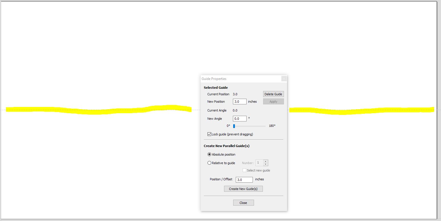
It’s a little hard to get your head around at first, it took me a try or two myself. Where you register zero does not matter at all (if using the two pin method). The pins are not along the edge, they are one centerline of your job. Either vertical or horizontal, does not matter, but you have to decide that when you create your new project and tell VCarve the material bounds and which way to flip. I did one using the edge method you’re describing, but unless you have an absolutely straight, square, same one all sides piece of material (not likely with wood) it will never be perfect. If you use the dowel pins you currently have to only square your material the first time, that’s ok, but the registration holes you drill into the wasteboard, then side 1 & 2 have to be centered on the flip. You do not re-zero X&Y on the flip, just Z, so where the original zero is irrelevant. Screenshots, maybe that will make better sense of my poor description:
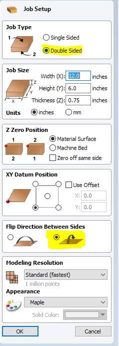
Job setup: Note that I chose to flip top to bottom rather than left to right.
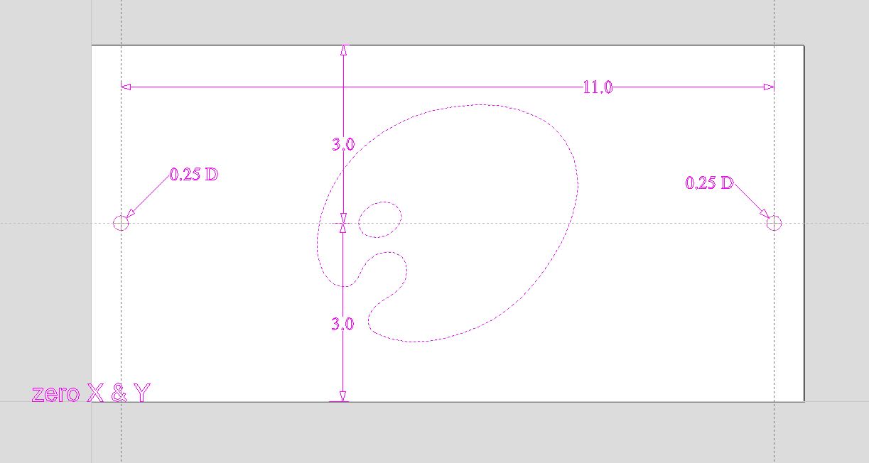
Side 1: note 1/4" holes for dowel placement. Drill these into waste board, then center your material as good as possible to this and drill same holes into material using this same drilling tool path. Flip material again, using pins for alignment, then drill same hole toolpath on opposite side (be careful not to go so deep you hit the dowel pins). Also note Zero X & Y, this is where you initially zero your machine.
Side 2: The material is now flipped, but machine zero x & Y stays the same (You can barely see where I put the “zero X & Y” text on the opposite side, it’s now at the top left corner, but machine zero stays the same (darker text bottom left corner)
Preview: In this preview I made the same profile 1/2 of the way through the stock on each side. Obviously it needs tabs and such, but this was my 2 minute example.
Thank you for the explanation of what you are doing. It all makes sense but is there a particular reason that you would not drill the holes through the material and into the waste board in one step? Maybe I am still not grasping this concept and running some tests would help bring it all together. My thought is that it sounds like drilling waste boards holes… aligning center of material to these holes as good as possible and then drilling holes into material leaves room for error? Whereas putting down you material and running the drill tool path through it and washboard at the same time means there is no room for human placement error…
I have to run some tests on this over the weekend so I can get a better picture of this process. You did make it clearer for me though with all your screenshots! Thanks
Yes and no, haha!! First reason being that for my projects I’m usually using as much Z depth as possible. To have a drill bit long enough to cut all of the way through and make it into the waste board I’d never clear on the up moves (I also have an extra 3/4" MDF waste board on top of stock). The first project I did like this was I believe 2 1/4" thick, the one after that was 1 1/2" thick. If I was doing something like 3/4" or less it may have been ok. Also very long drill bits could feasibly deflect more by the time they hit bottom. I use short length drill bits from McMaster-Carr
I also use peck drilling in VCarve and only spin them at 5000RPM (I have a SuperPID + Dewalt). You could probably spin them faster and adjust the plunge and such to work ok as well (I think I did this prior to SuperPID install, can’t remember).
On thinner stock I could probably get away with the holes in one shot.
Thanks for clarifying why - I bookmarked the instructional video from Vectric on two-sided jobs. I didn’t even go looking for it until late last week. Been so busy with outside work that I haven’t had time to look at much. Hope to watch that video and use the info from this thread to give it a shot on some scrap material.
I have found a video on YouTube which seems to really simplify the set up one can use for flipping a piece and maintain proper alignment. Best part is it sort of works the way I already set my wasteboard up with dowels to line my stock up to insure it’s square to the X/Y travel of my SO3 -
Vectric has several videos but they are all bloated with additional details of the project they are running. They also talk about the non symmetrical method of dowel placement as being superior for a few reasons but they don’t choose that method for the tutorial… lol. I sent them a gentle suggestion to create a Tips/Tricks style shorter video just showing the software set up for dowel placement and the corresponding actions take on the CNC machine bed to insure one can flip material and keep perfect alignment. Until they do, this video seems to really nail a simple way to handle this… can’t wait to try it out tomorrow!