Workholding help, milling a finished product

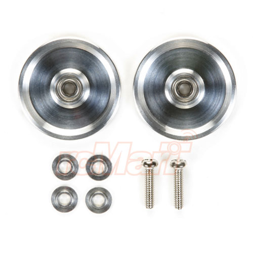
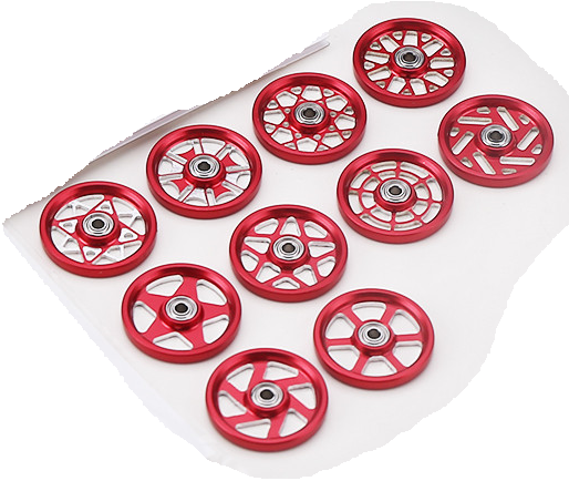
I have a bunch of these different carbon fiber pieces that are already cut out in various sizes and shapes. I currently am creating pockets of the shapes outline in acrylic and press fitting them inside, then running the gcode to cut out what I need from it. This method works, but it’s tough because the company that makes the carbonfiber products don’t have strict tolerances so sometimes I gotta sand it down to fit, but I digress. Is there a better way to workhold than what I’m doing? I need quick repeatable process (Job is done, reset job zero, put the next piece, hit run ) These pieces are 100mm wide usually and 7mm tall. 1.5-3mm thick. and I would like to cut like 12 pieces at a time.

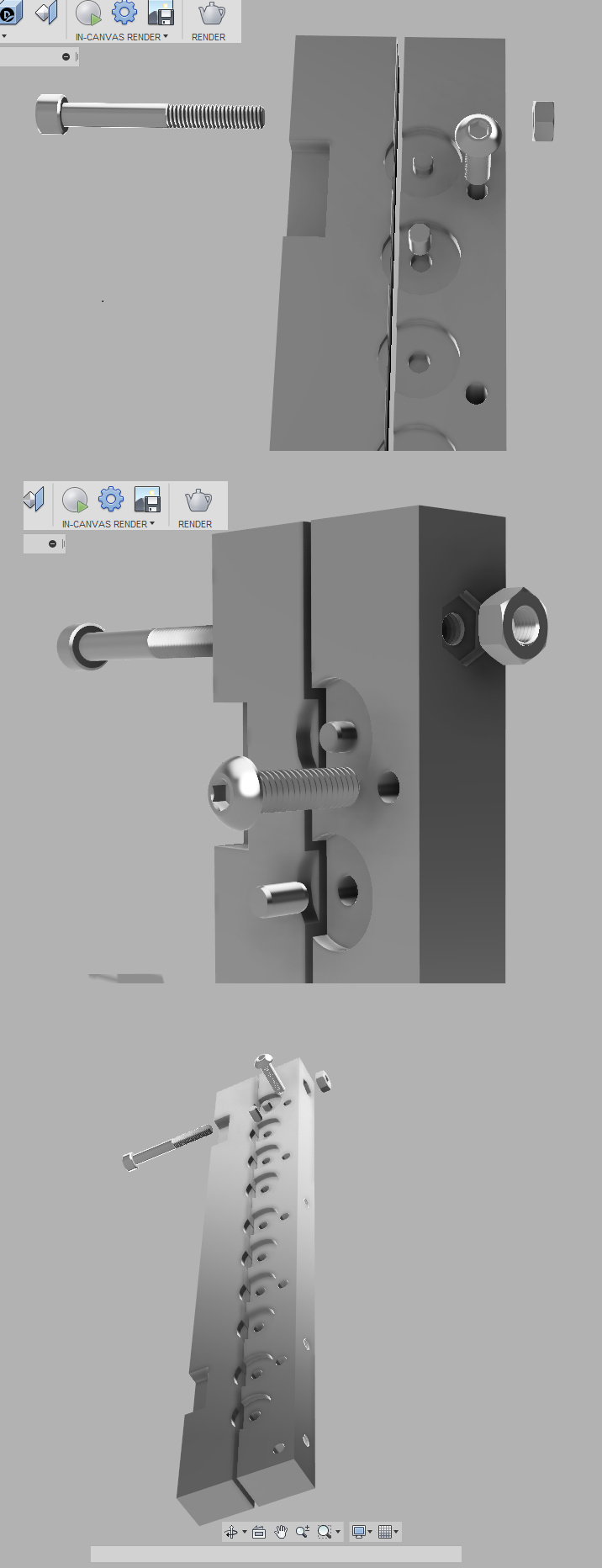
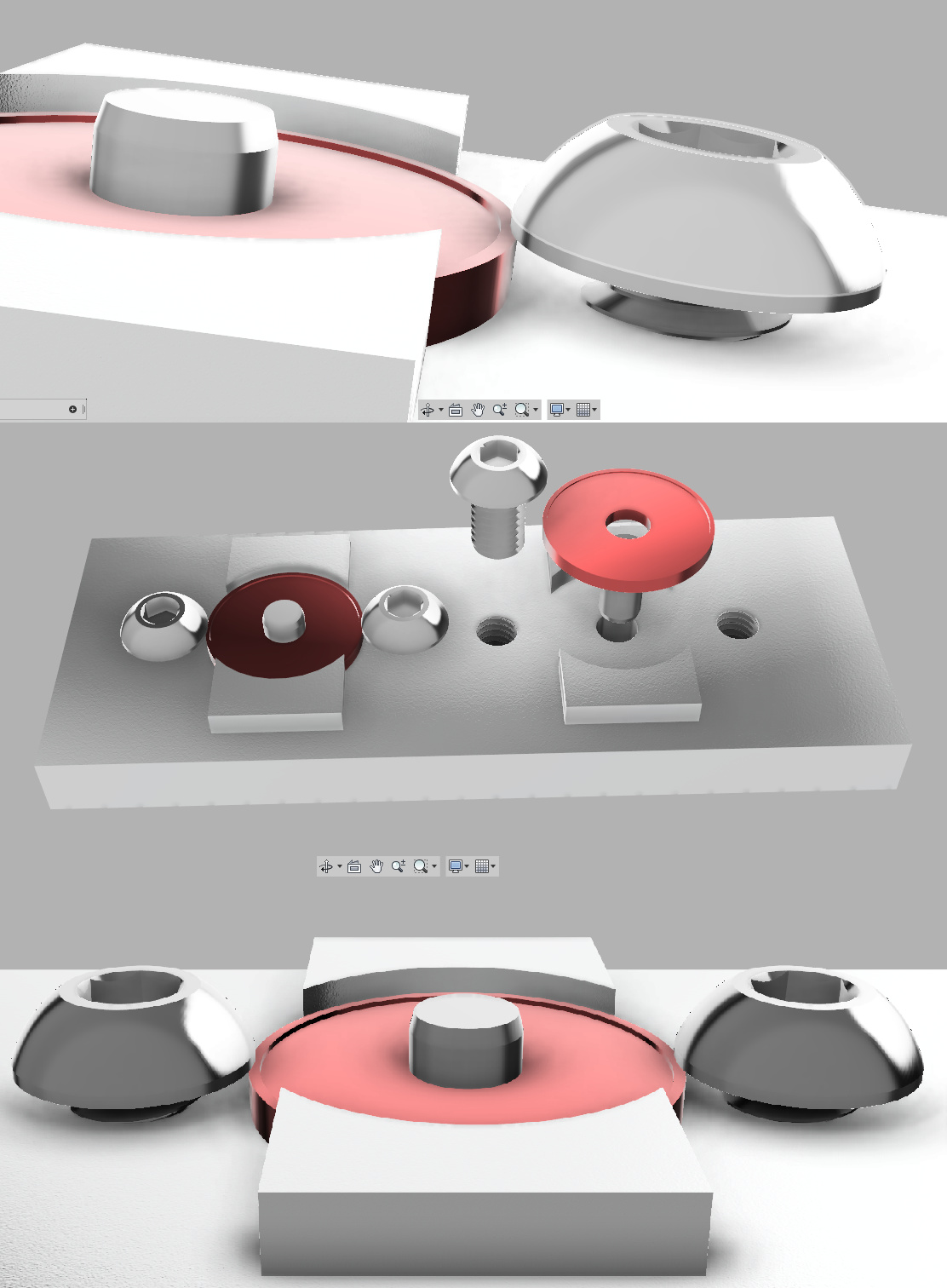
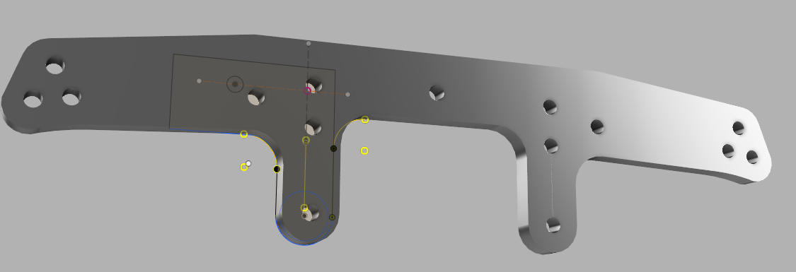
Here’s the first example, I need to mount this object, and cut out that little “L” on the bot left. You can see the sketch. This one I’m having trouble with tolerances with the outline, and i’m trying to think of a better way to do this.

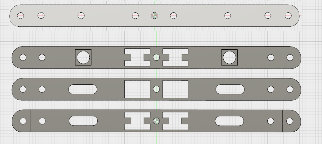
Here’s second example, top piece is original stock. Bot 3 is what I need to cut out or recess.

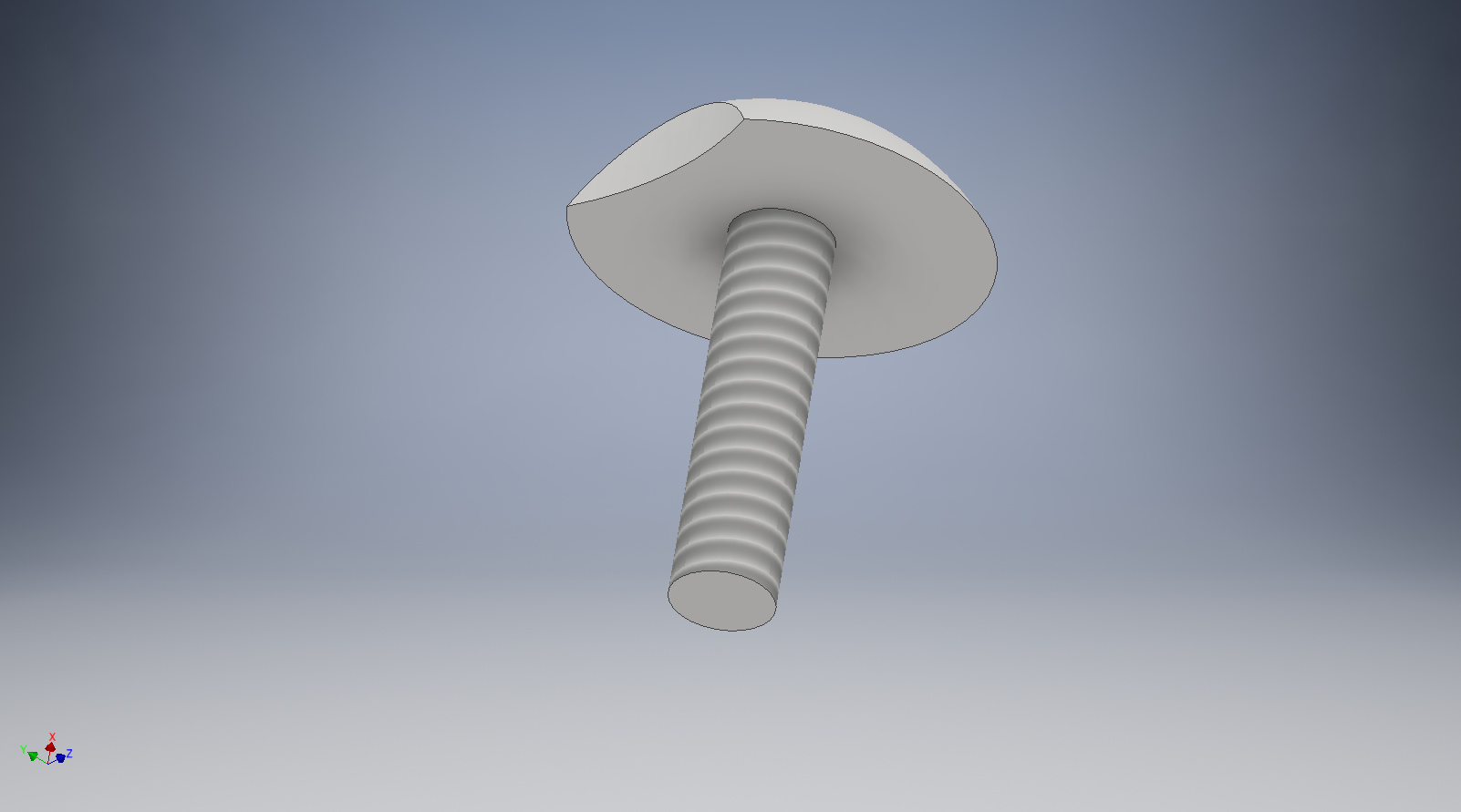
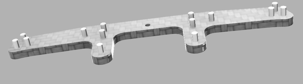
I was thinking of something like this, 2mm dowels and insert into the base as pegs. I need something sturdier than wood, so I was thinking acrylic or PCB board.

Any advise is welcomed, thanks in advance!

1 Like

If it were me, I would use the holes that are outside the cut zone to hold down and position, possibly with additional hold down near the cut zone.

Dowel pins are cheap ($US0.24 each in 316 stainless, 12mm long) and very precise. A couple dowel pins to locate and a couple 2mm screws to hold down will do it. If you are using MDF and MDF wasteboard, you can put in the holes using a 1.5mm (or 1/16") tool, maybe 0.02mm undersize for the pins so they lightly press fit, and pretty much a plunge then tap for 2mm (M2-0.4) button head (or round heat, or socket cap head, or… )for hold down. Truss head (larger seating surface) do not seem to be a catalog item in 2mm, but may be available. I would use a washer, myself, but for rapid changes, washers are a pain. M2-0.4 button head are about $US0.22 each in hex socket drive. The tap is about $US15. for a spiral point good quality tap (the only type worth buying for through holes, if you arn’t fond of poor thread quality and broken taps) Prices referenced are McMaster, but other suppliers are similar.

Powered driver to insert and remove screws, and fast, uniform turnaround. (I would actually use a manual spiral driver, myself, for control, but, then again, I have a lot of them).

If you want a bit better dimensional control, remove the stock waste board (Nomad) and replace it with either a piece of aluminum plate (to protect the factory bed plate) in 8 or 12mm (3/8" or 1/2") or acrylic in the same. On a Shaeoko, glue it or screw it down to whatever you are using as a bedplate. Acrylic is nice because it is cheap and machines easily and takes press fit dowel pins like a champ, but before pressing the pins, you need to chamfer top and bottom. If you do not, the surface will not be flat near the dowel pin. When you bolt it down, snug, but not too tight, because it will pull out of flat. Bore the holes for the positionint pins and hold-down screws once the plate is in place.

If you are using a Nomad, the drill pattern to hold this to the bedplate is the same as the stock wasteboard, and can be done using the machine itself. The dimensions (and maybe even a CAD model) are somewhere on the CD site. I haven’t looked in a long time for where, but I grabbed it all when I got my machine.

1 Like

Thanks so much for this, I will try this immediately!

I’m actually on a shapeoko XXL (I know…why so big to cut so small…I can’t even answer) , but I do have a 1/4’’ thick aluminum sheet to replace the MDF board as the base , and then drilled and tapped m6 thread holes 2’’ spacing.

THANKS SO MUCH!!!

Tested this method out and it worked so beautifully I almost cried. It’s so easy even for ppl who aren’t cnc trained to setup and run the program. Can’t thank you enough and really appreciate your help!

If you don’t mind, I have one more question for workholding.

This is the original product:
19mm outer diameter, bearing is 520 (5mm outer dia, 2mm inner dia)
tamiya-15464-1

This is what I want to CNC with it:
rollers
rollers

Can I do the dowel pin again? or is there a chance that the roller could spin. I was thinking 5mm dowel pin, and double sided tape maybe would be enough, probably not thou.The milling area is not thick at all, maybe 1mm. Do I need something on the outside of the roller to hold it in place? maybe some sort of 3D printed clamp that I could tighten (mitee uniforce clamp (kinda expensive https://www.mscdirect.com/product/details/37163185) and screw into the waste board. Just spit balling ideas, I’m sure you got the better one.

Are you starting with round stock or plate? Or are the wheels already cut and you’re just doing the reliefs? If you’re using plate stock just screw the whole plate down at the corners and use tabs. If it’s round stock you could maybe drill the center holes on a lathe, then bolt the middle and double sided tape the rest, ditto if you have nearly complete wheels and just want to cut the reliefs (spokes).

edit: NVM the first parts, I didn’t see that you where making one product from another already existing product. You could also make a fixture like I used here:

Dan

I thought of that, but just curious, my objects don’t have that little nob on top of the circular thing, so you think the object will spin if it’s just pressed into MDF with a dowel in the center? Just doing relief cuts and I’m only cutting through 1mm at best.

I drew up this jig in fusion, but maybe I’m over complicating things. The button head goes into my base plate (my base plate has m6 threaded holes) The cap screws will add the tension for the vise like thing. and the rectangle cutouts are for my clamps because the 2’’ hole spacing I have don’t match up.

I think maybe you’re over complicating it a little, I think a simple pocket with a screw on each side like I did on my ornament jig would work perfect and if you make the pocket tight it won’t spin. I think I made my pocket 0.010" oversized compared to my ornament OD and they fit nice and snug. I used simple 1/2" wood screws in two spots right next to the pocket and once they were tightened nothing was moving. Question though, how many do you plan on cutting? On my jig after about 60 cuts the screw threads started loosening. If I were to do hundreds or thousands I probably would have used a machine screw with an insert in the MDF (and maybe switched to a different material, maybe HDPE) , then added a washer to capture the edges of my work piece. I also thought about putting a couple small pieces of 2 sided tape on my pieces, but in the end the screws works so well I didn’t end up trying it. The full side clamp idea you have would probably work too, but I doubt it’s needed (also side clamping doesn’t ensure a flat work piece. Of course cutting aluminum you’ll want your speeds and feeds pretty slow with a small depth of cut. Curious to see what you come up with.

Dan

Plan on cutting a lot, prob hundreds but over a period of time, 3 months? Also, need this to be easy for anyone at the shop to take off and put on the next lot. I will try the recessed cut at 0.010’’ bigger and see what happens. Thanks so much for your help will report back with my results.

Not a bad design, but for ease of use, the right hand side needs clearance. If the pin is locating the part, then you do not want any other contact on the right hand side. If the pocket is locating the part, then you want no pin. With both, either the par will bind going in or the pin is taking full load anyway.

I would use the pin and make the 3/4 circular pocket on the right a deck with edge clearance for the part. The pin needs more engagement into the fixture that you show, or it will work loose quickly. If the pin is set well into the fixture (3 or 4 times the stickout the part engages), and the fixture is made of reasonable structural material (acrylic or aluminum, for example, not MDF) that can take repeated cycles of loading during clamping, it will outlive you and me.

This doesn’t provide any hold-down, but given the size of the part and the job, you can probably get away with that. If lift is an issue, you will need hold-downs. I would use a button head screw on each part of the fixture where the edge of the screw just barely engages the edge of the part (maybe 0.1mm) to hold it down. The clamping action for primary holding, but the screw to keep the part from climbing.

I think I understood what you said, but just to be sure…

This way it’s the dowel taking all the force, the button head screws keep it from lifting, and the top and bot is just extra insurance doesn’t need to be super tight tolerance. I should of choose a smaller button head but oh well, I’ll make sure they don’t touch in the final jig.

1 Like

I like this method :smiley:

Dan

That is the general idea. There are many ways to implement it. Yours is actually cleaner than I was thinking.

The dowel locates the part (positive) and takes lateral force (positive), the screws keep the part down (positive) and prevent rotation (friction).

Your prior design only holds down with friction, which can be an issue if the part can deflect, the holder can deflect, the holding faces are not true, or there are high forces in machining. It also requires the operator to seat the part (usually with a soft, dead blow, hammer) to compensate for lift during clamping.

The dowel need not extend above the top of the part. It needs to engage sufficiently to locate it and resist lateral forces. Keeping it just below the part top means you don’t need to worry about hitting it with the tool.

The hold downs need not be full head screws. The edge of the head can be ground back so a quarter turn releases the part. This is done by mounting a part, marking the rotation, and then removing the screw to grind. A light taper underneath the head to give some lead for engagement can be helpful if the thread pitch is too fine (think a cam lock for a double hung window). If you do this, each screw will be married to its hole since the grind depends on the exact clocking of the threads, but once they are done, they need never come out for part handling, so it isn’t a big deal.

If the head is outside the machining area, the head size doesn’t matter, as long as you tell your CAM software that the heads are there. Most CAM software has a way to let it know that there is a fixture/vise involved so that it can be avoided.

Edit: example of the screw (5 minute model)

Amazing idea for the screw heads, I LOVE IT!

Thank you so much for your wisdom. I sincerely appreciate the time you took to explain and to help me learn.

If you asked me what was the hardest part about CNC’ing 2months ago when I started…work holding wouldn’t even be on the list. Right now work holding these specific pieces and getting familiar with Cam on fusion 360 are my bottle necks. so I really can’t thank you enough to helping at least make the work holding easier for me.

I can’t ake credit for most of the concepts I bring up. I have learned from some very good people and done what I can to absorb some of the best references available. Google “Colvin and Stanley” jigs and fixtures (pn google books) for a starting point. They may be old (late 1800’s to early 1900’s, hence being out of copyright), but the concepts still apply.