XXL Upgrade - Unboxing and Construction

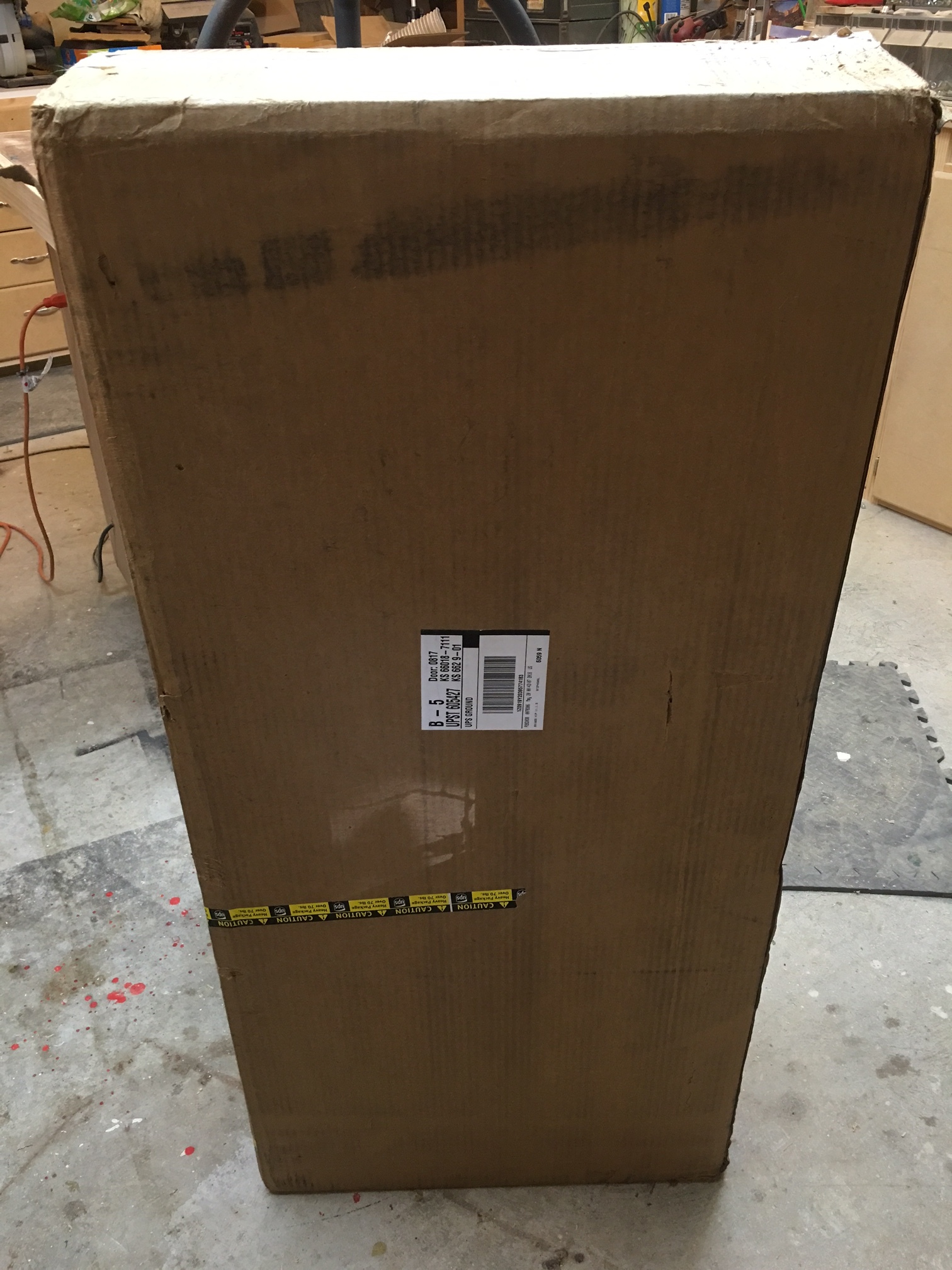
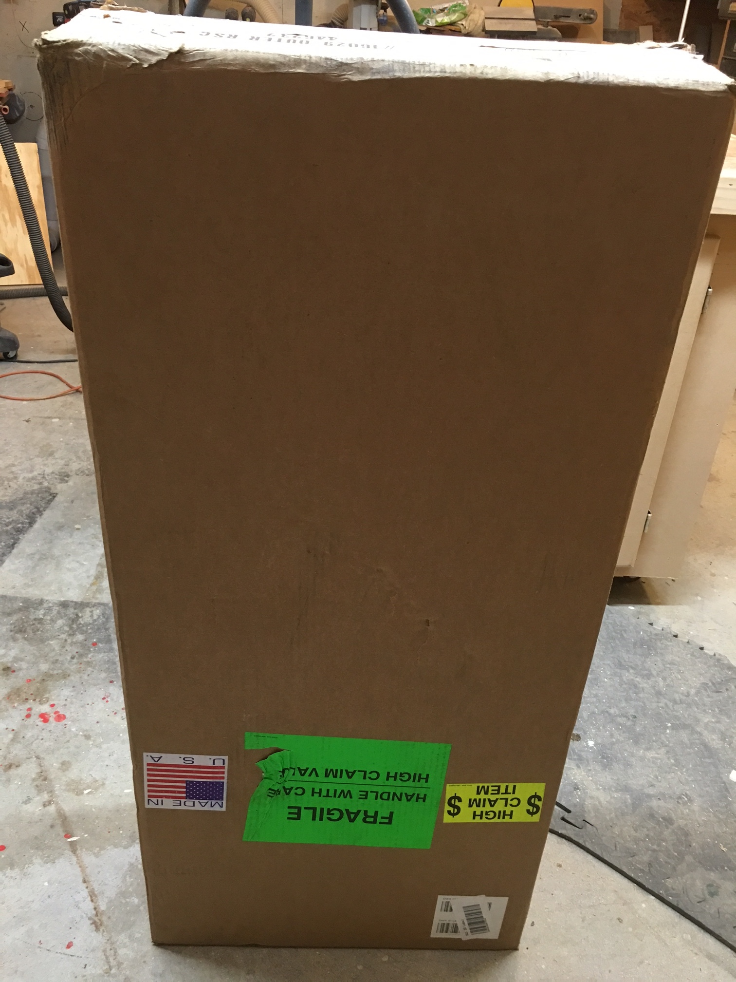
My XXL Upgrade kit arrived on Monday. 110 pounds of fun. I thought I’d share the unboxing and then the steps to perform the upgrade.

The box arrived with minor dings. Not too much damage.


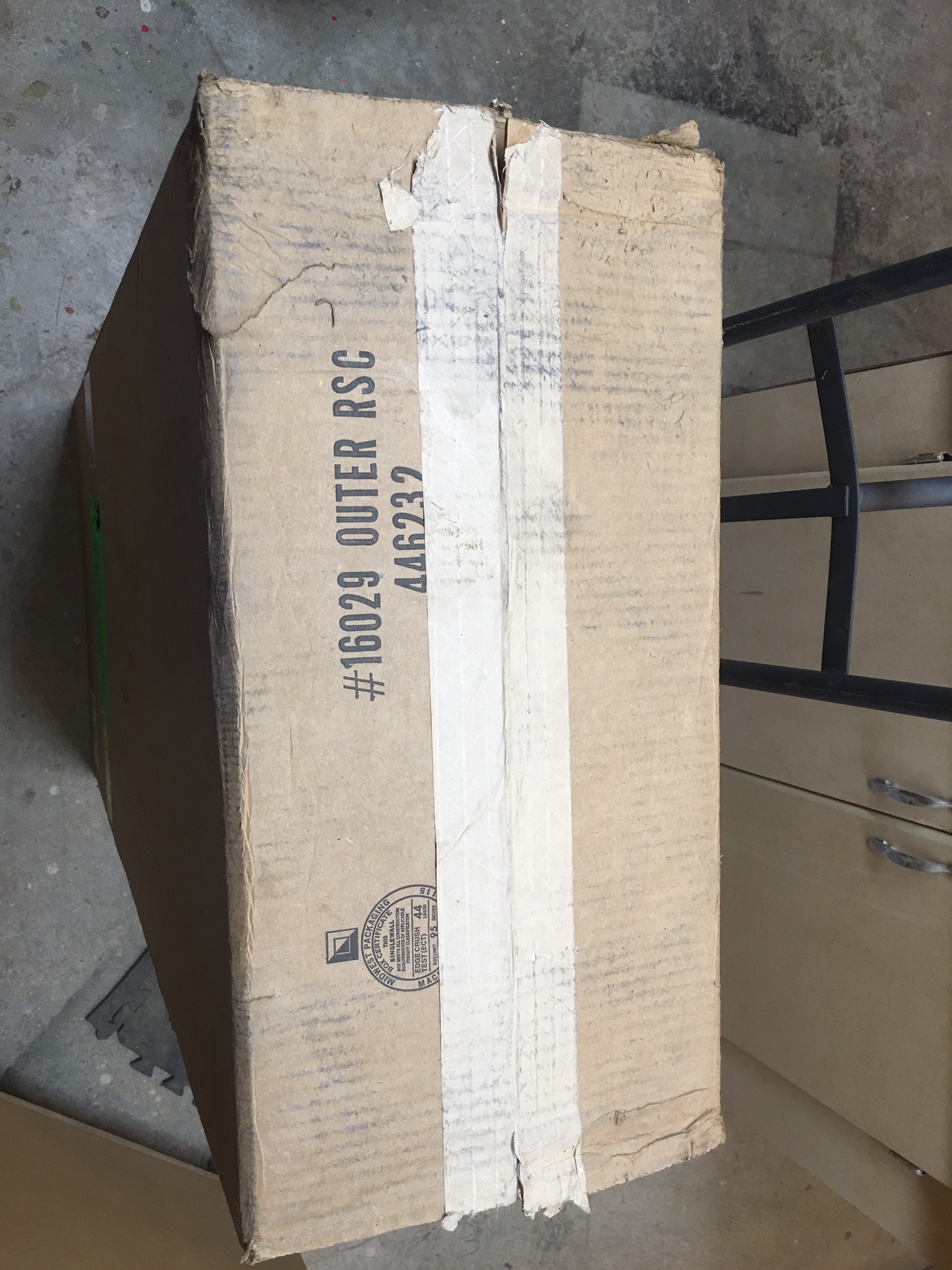
Once I opened the outer box, I found that there was an inner lining as well. This is good, less chance of damage. Once I opened the inner shell, there was decent corner padding and empty boxes filling any voids.

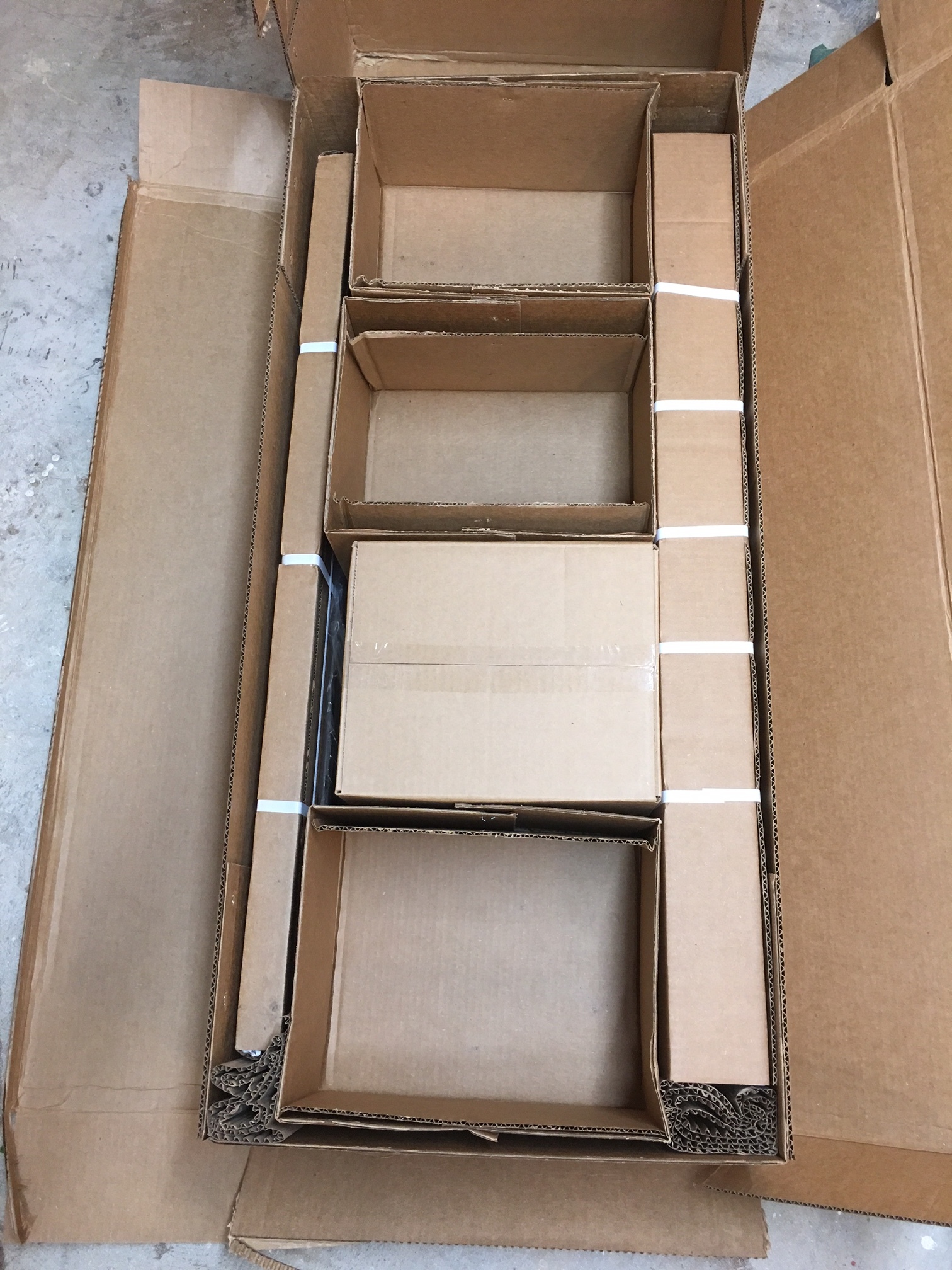
There was no bill of materials in the box, and no instructions on performing the upgrade. This was a little disappointing. How do we know if we received all of the parts we need with no BOM?

All of the smaller upgrade parts were packed together in a box. The following photo shows everything I received.
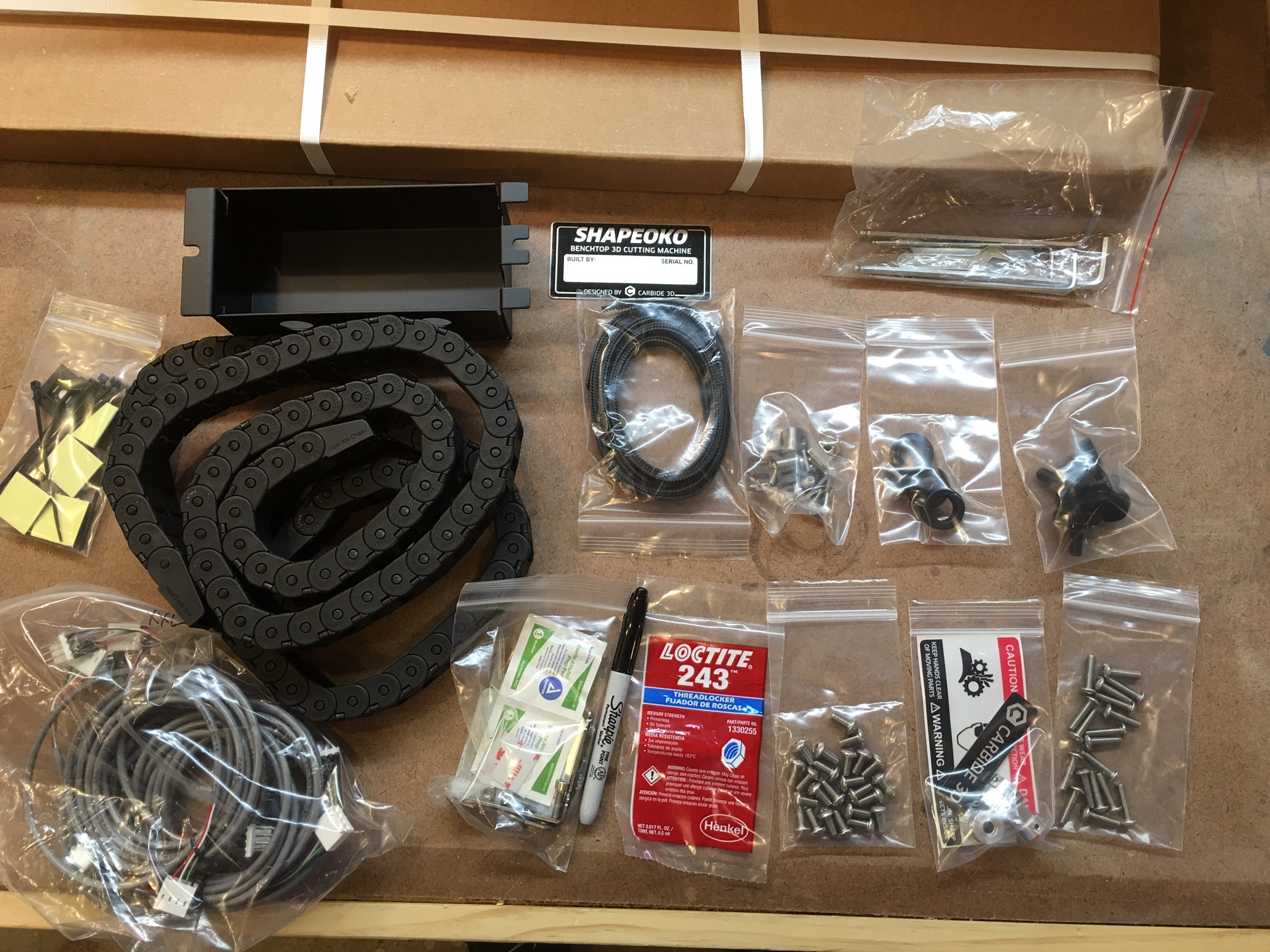

Included were -

  1. Zip ties and cable management tabs
  2. Electronics enclosure
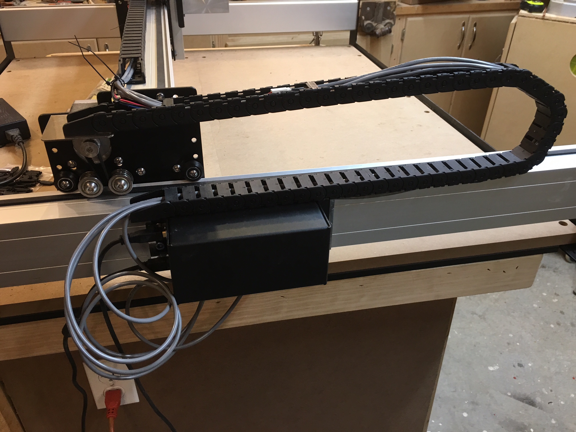
  3. Drag chain
  4. Drag chain brackets
  5. A Sharpie
  6. Serial plate
  7. New belts
  8. Belt tension brackets (new style - no more tiny hex nuts)
  9. Grommets for electronics enclosure
  10. A bag of tools
  11. Screw in feet
  12. Cable extensions for motors
  13. Tube of Loctite
  14. Bag of screws for the extrusions
  15. Warning sticker and Cabide3D sticker
  16. Screws for the waste board/base assembly
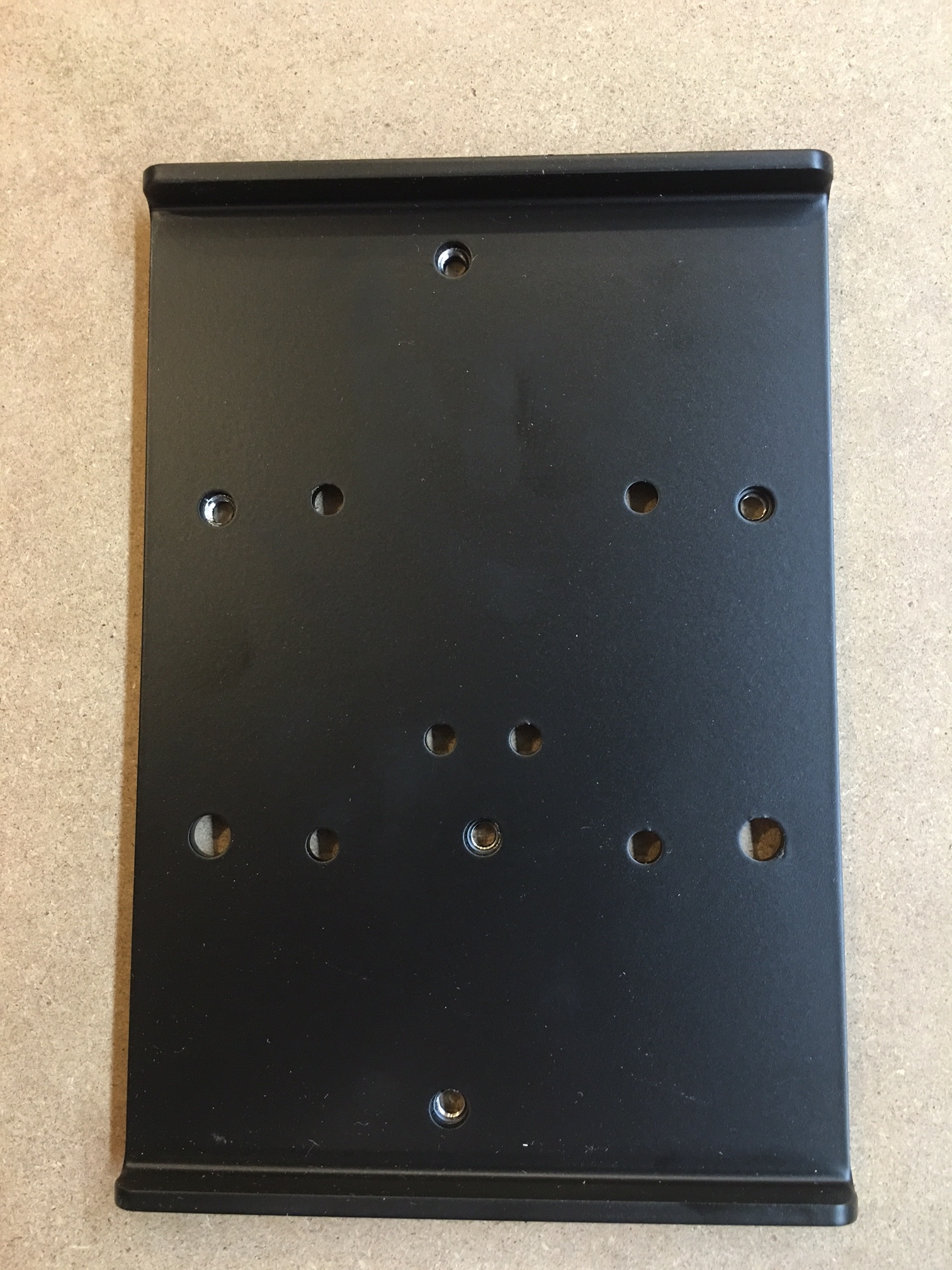
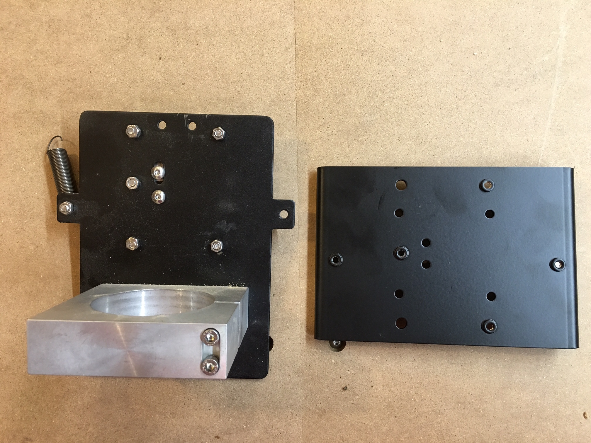
  17. New Z plate for mounting the spindle
  18. 3 40" rails
  19. 2 front/rear plates
  20. 3 cross straps.
  21. 3 new G9 pulleys

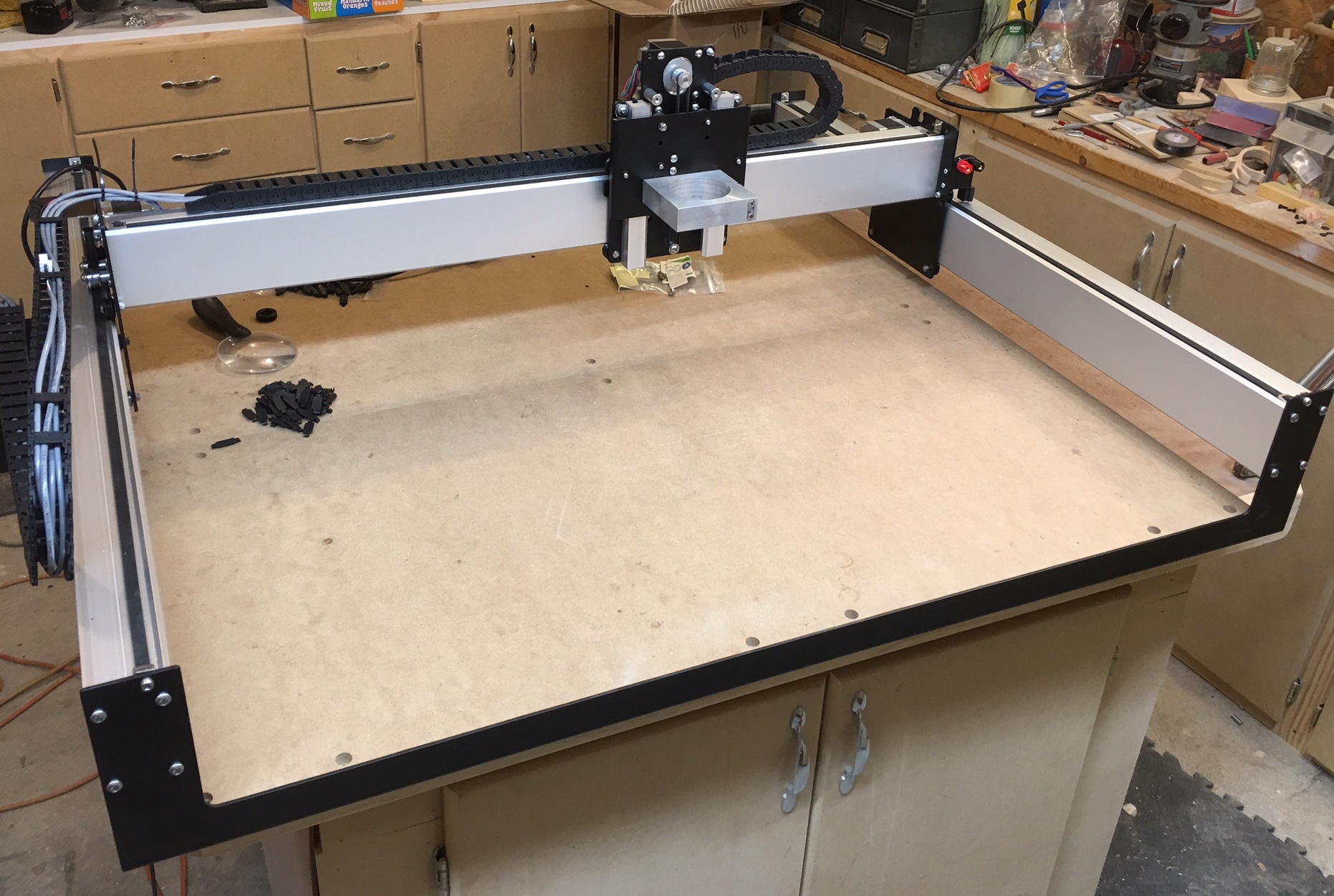
Once I laid out all of the materials, I started assembly. The front and rear plates, the cross straps, and the spoil board screw together just like the original S3. It is just bigger.

I did have minor damage to one corner of one piece of the spoil boards. the damage ended up being on the underside, so it should not cause any issues.

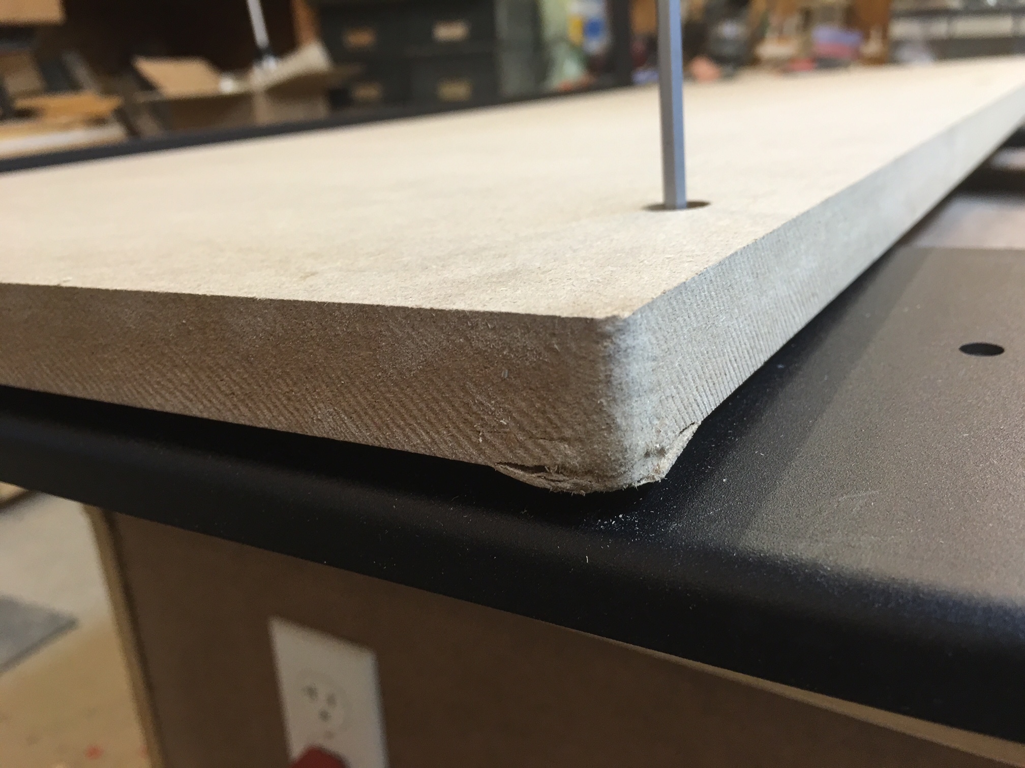
When attaching the spoil board through the cross straps and into the front plate, I could not get the screws to go deep enough to get into the front plate. So I drilled out the hole in the spoil board to gain enough length to reach the threads.

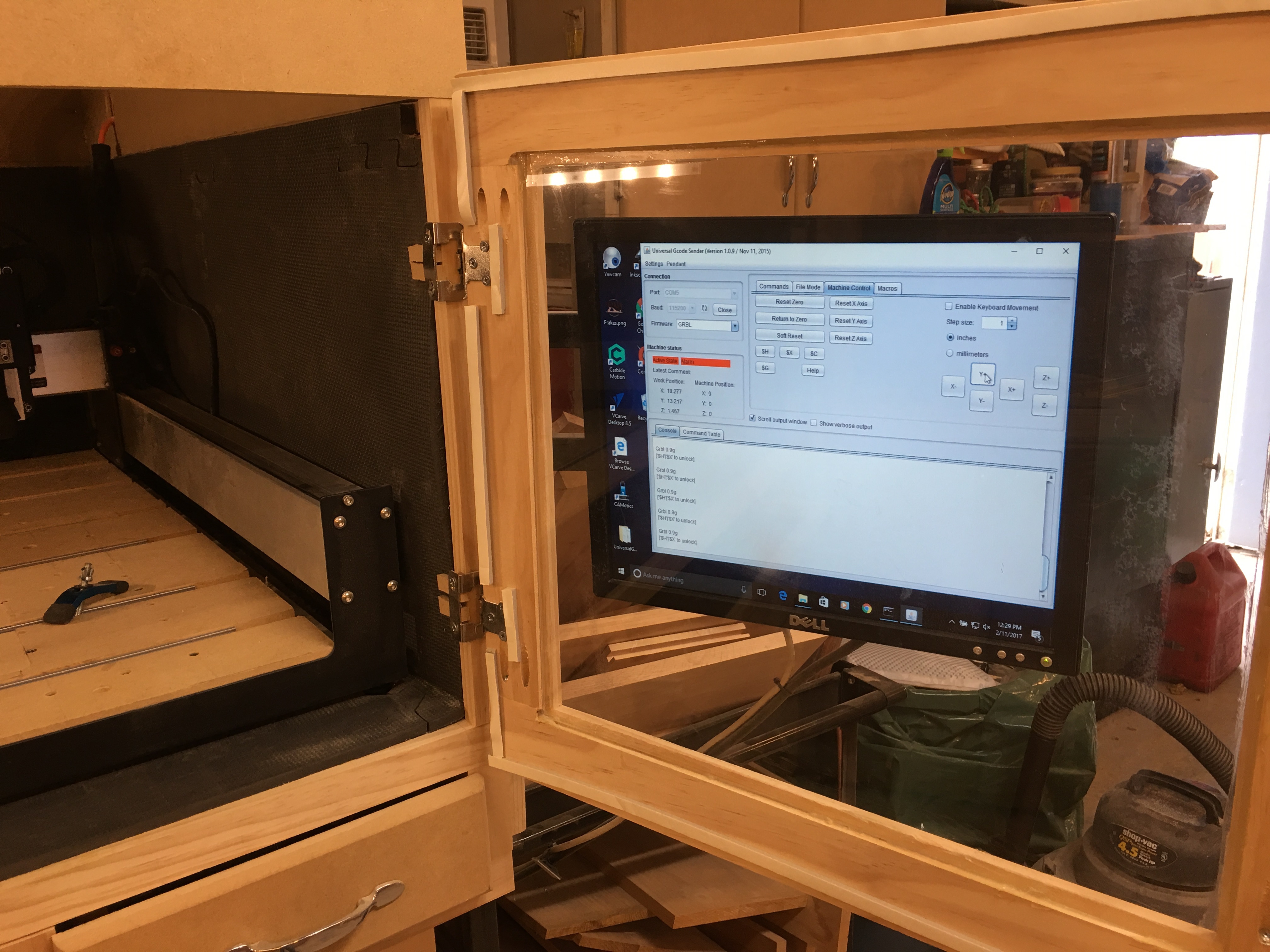
Now the base it put together. Here is a picture of the original S3 sitting on top of the XXL.

I found the base went together pretty smoothly once I had everything lined up. A couple clamps helped.

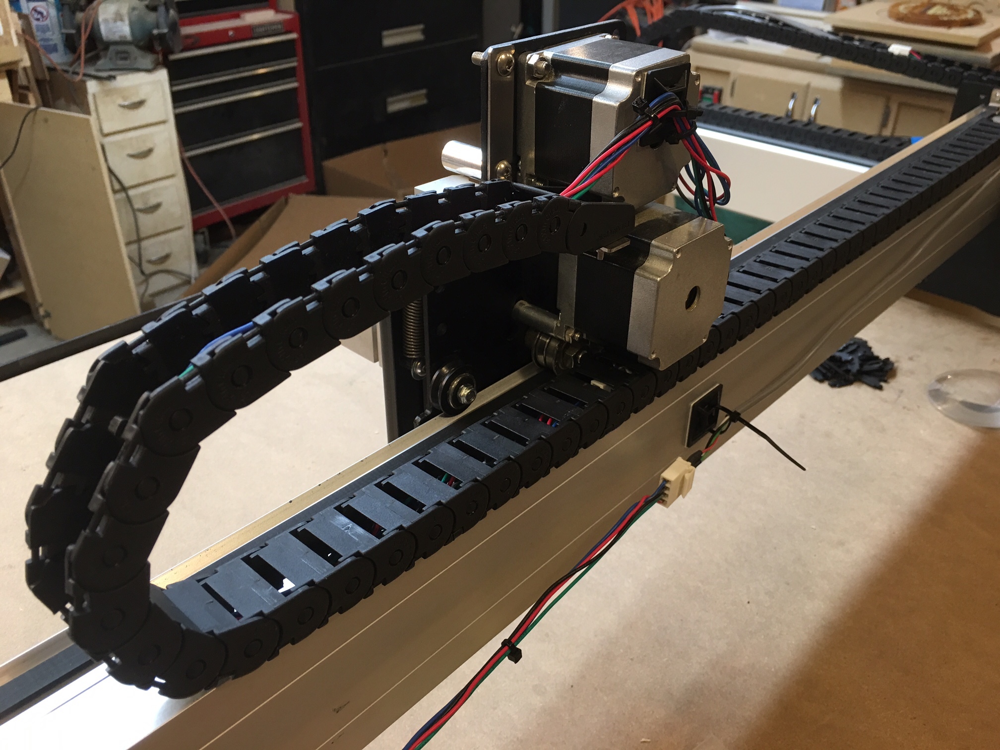
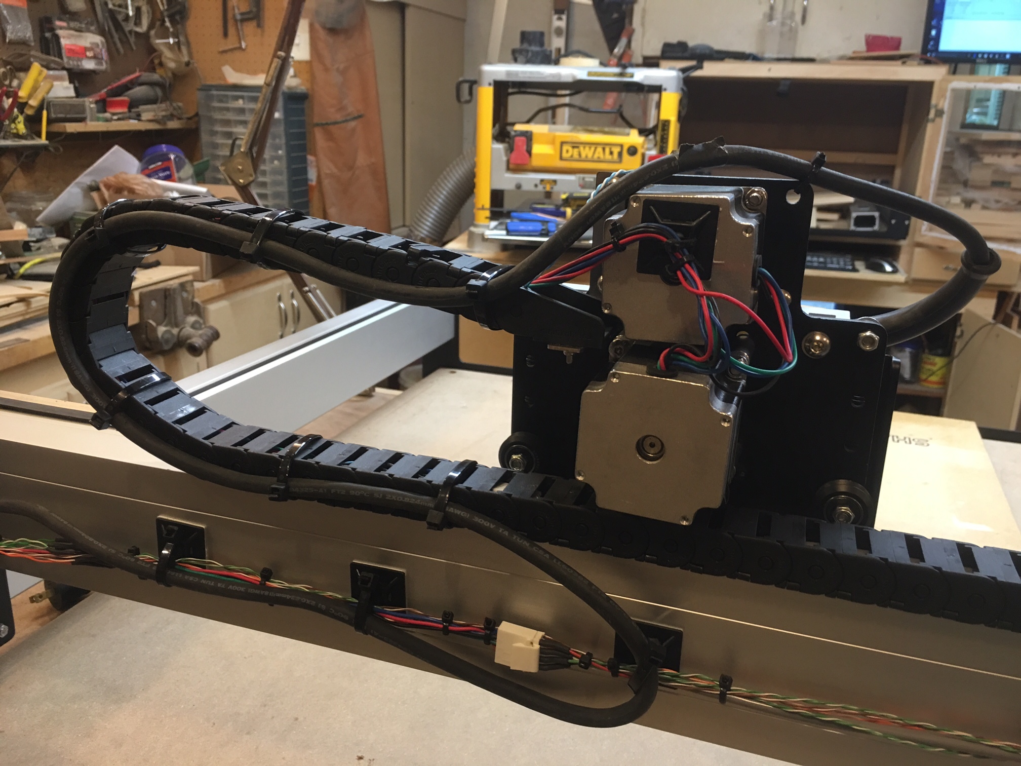
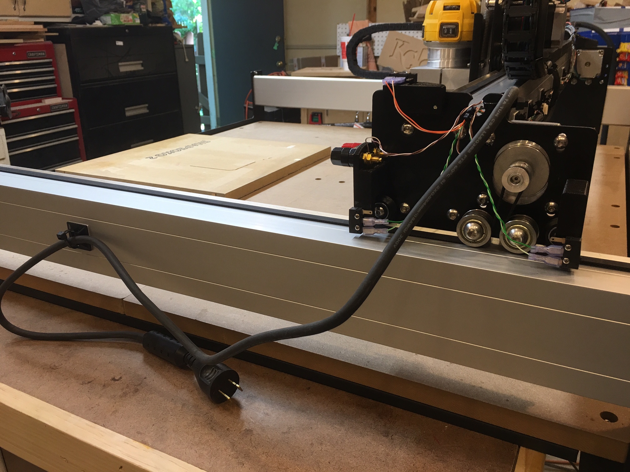
Next I went to work disassembling the gantry and rails on the S3 so I can move everything over to the XXL.

I am now in a holding pattern until I receive new v-wheels (I had a crash last Friday and broke several of the v-wheels), so my upgrade came at just the right time since I had to disassemble everything to fix the broken v-wheels.

I wish there were some instructions, but so far I have been able to figure out where everything goes by looking at the XXL assembly guide, but there are a few things not covered. Such as:

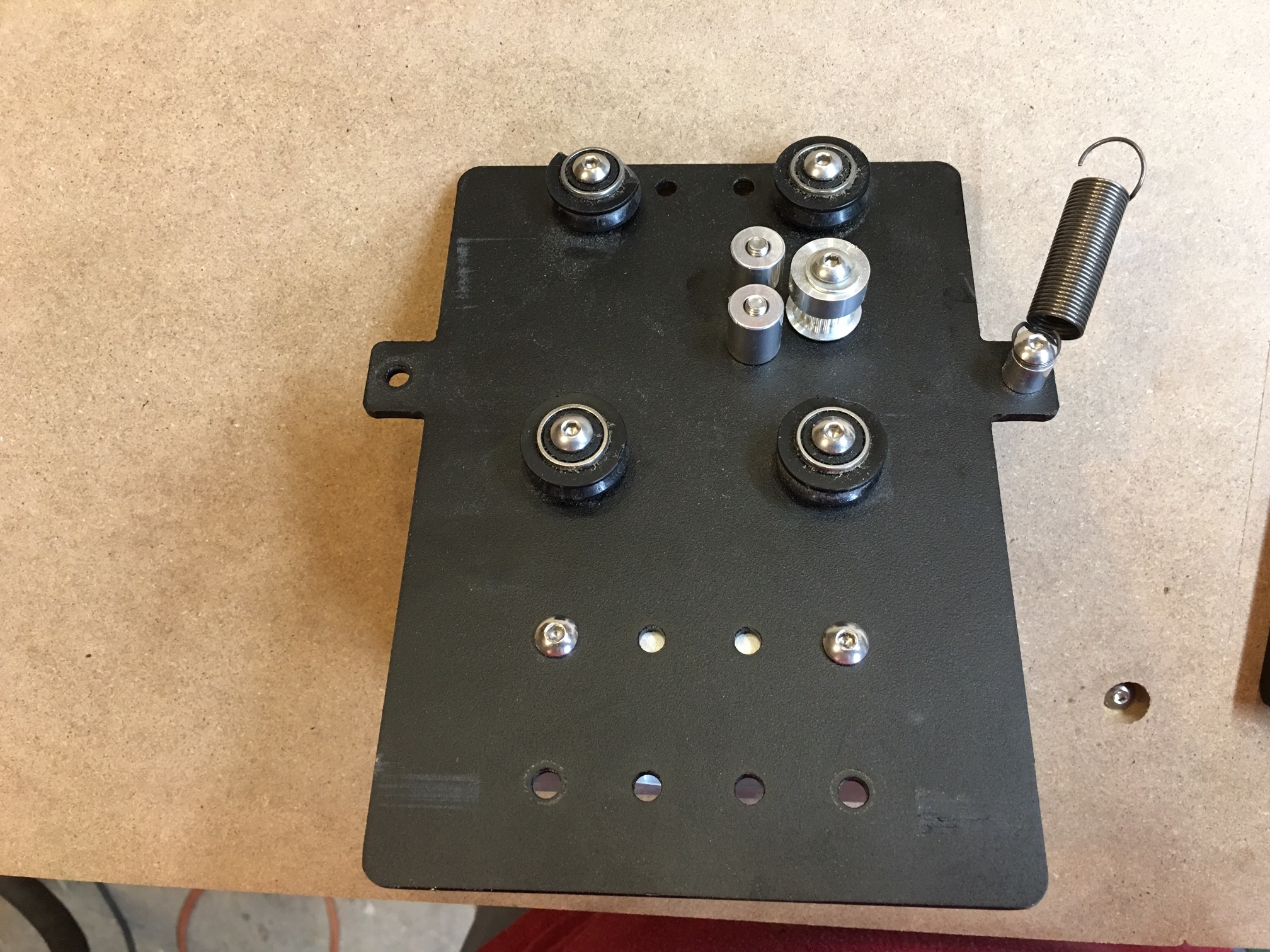
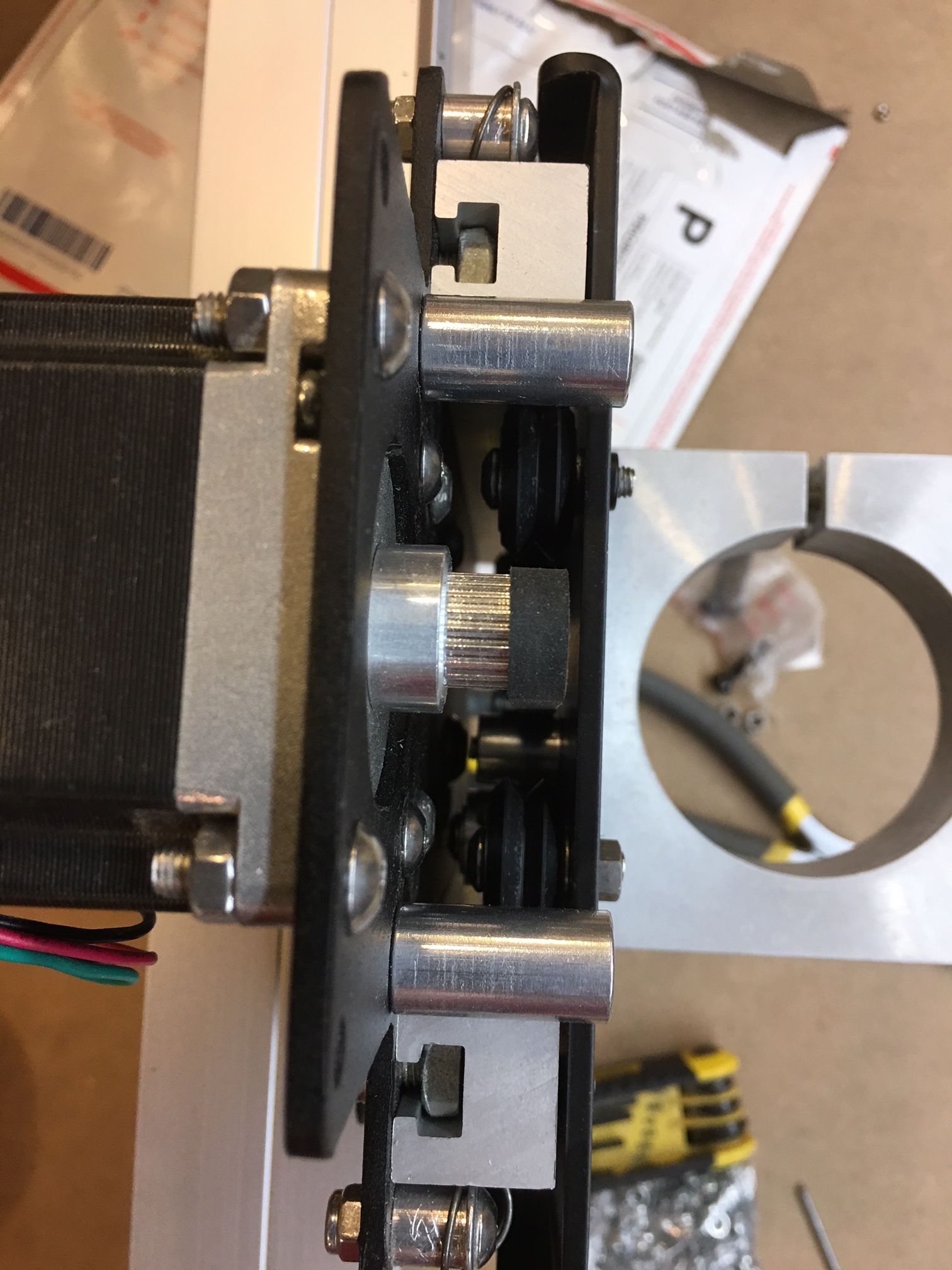
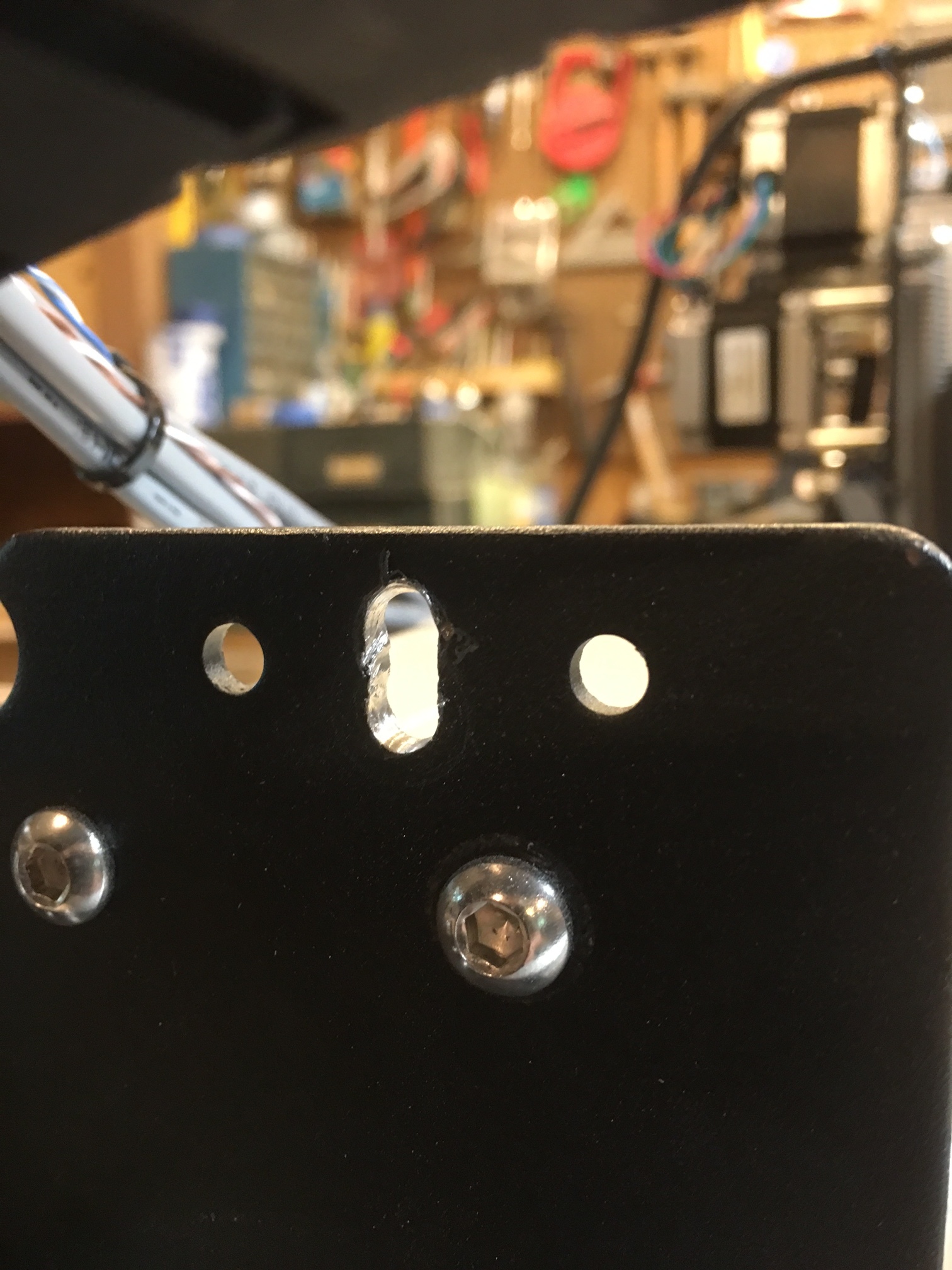
  1. The new belt tension brackets. There are 6 of them, just like before. The brackets now come with a socket head hex bolt and the bracket has integrated threads. This is nice because it eliminates the annoying little hex nuts the S3 used. The 4 brackets on the front and rear plates are self-explanatory, as the bolt goes through an existing hole. But the same hole does not exist on the carriage plates. Neither of the existing holes are large enough for the new bolt. So I guess I will see which hole lines up and drill out enough clearance when the time comes.

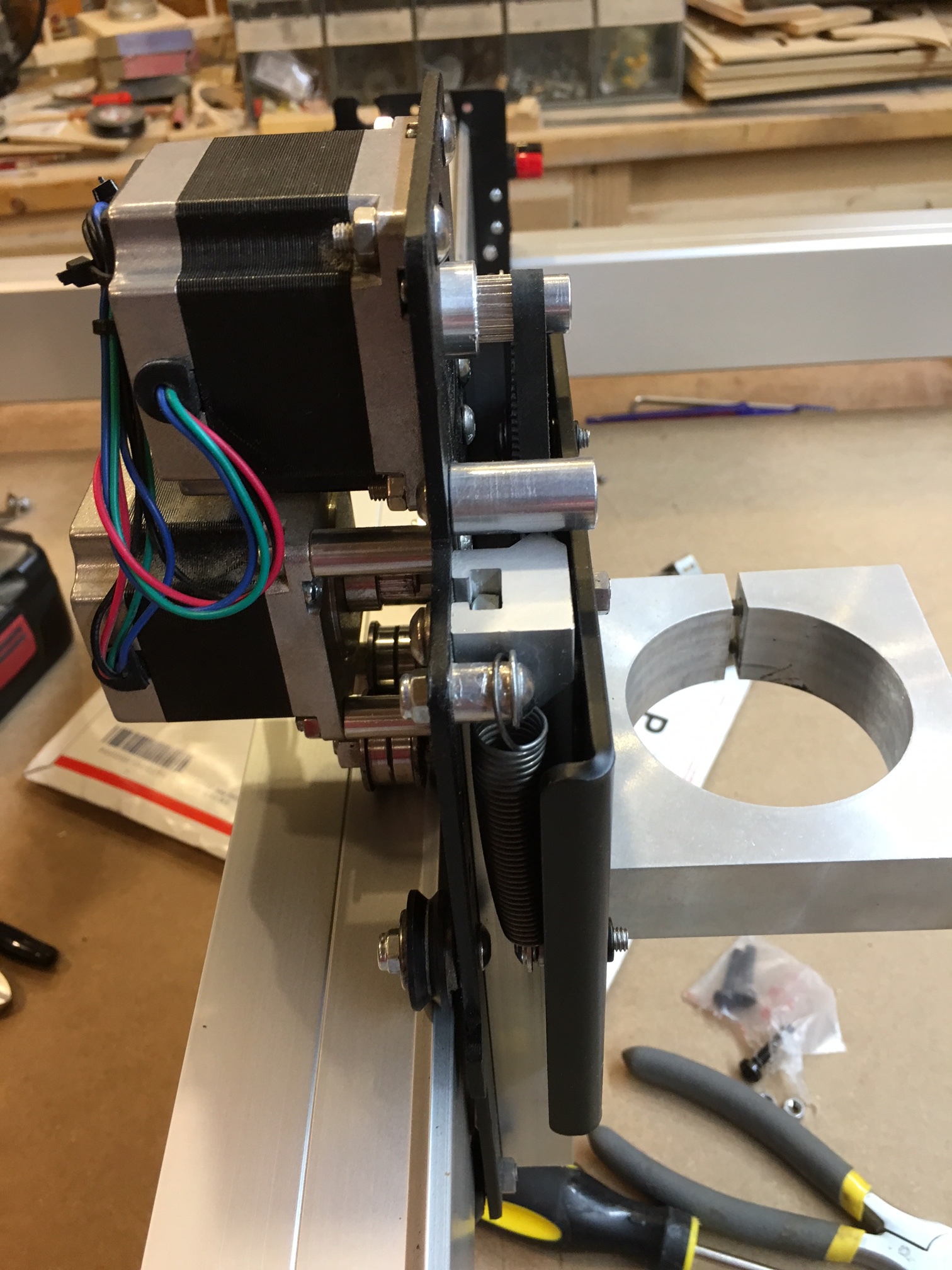
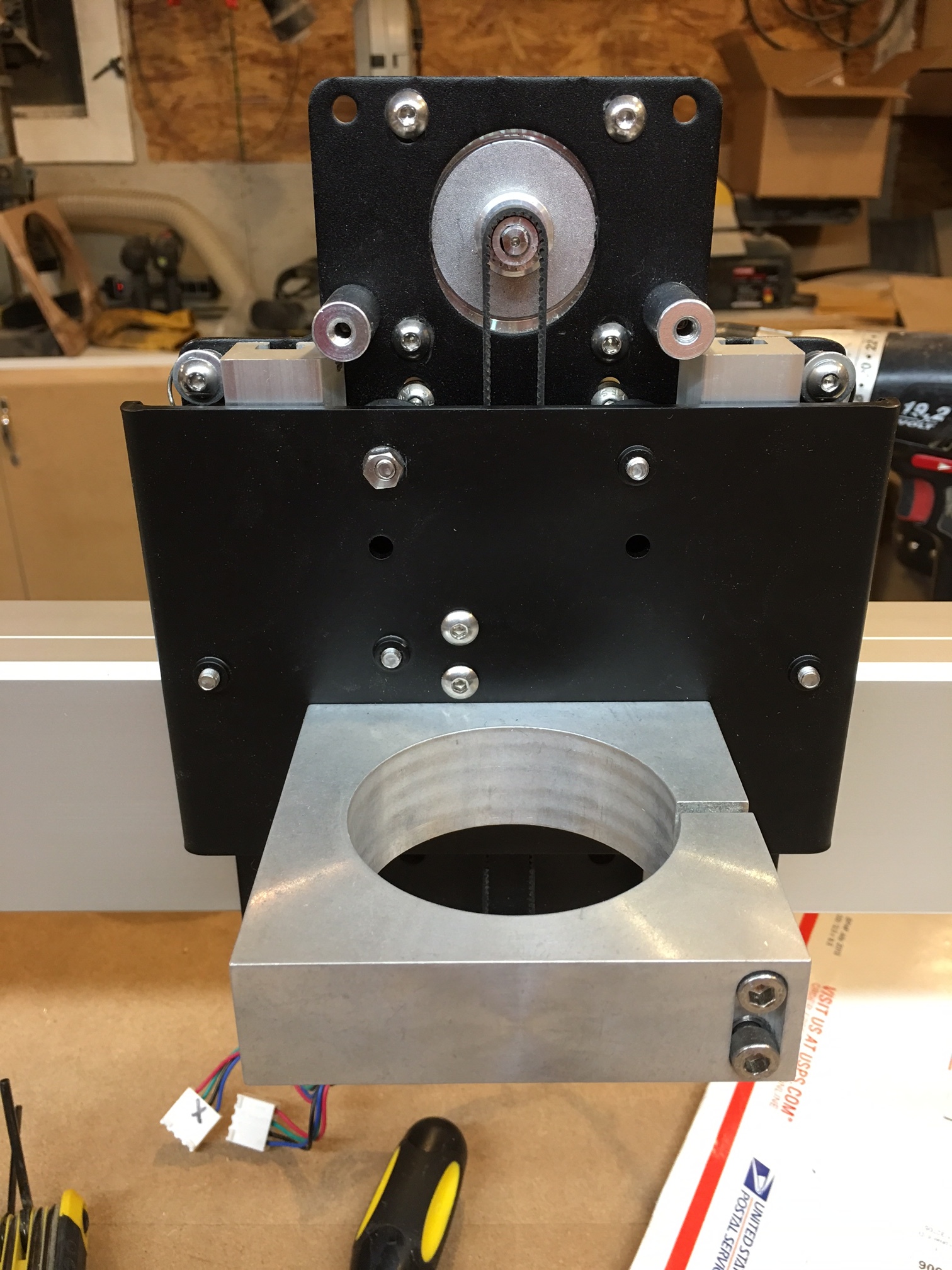
  2. The new Z plate. I will have to figure out how to assemble this without instructions I guess. I don’t see any ears for the springs to attach to.

I will continue to post as I move along. Hopefully the new v-wheels will arrive tomorrow.

1 Like

Thanks Will. I have that guide. Unfortunately, it is only somewhat helpful in the upgrade to XXL.

Are there any photos of the new Z plate assembled?

I would expect most everything would be similar between the two.

There are a couple pictures in the XXL guide, but they are already built. No exploded views or views between the plates using the new plate, or any instructions on moving from the old plate to the new. It shouldn’t be too difficult. Should just be a matter of moving everything over to the new plate in the same relative positions.

No limit switches? I guess that’s the price we pay for being the early adapters.

Edward - if you are reading this… don’t forget about us guys who are buying the expansion kits! We sat and watched all the new customers get their machines before us, and waited patiently. The lack of proper documentation at this point in the game for a product that I waited 3 months for is not sitting well with me.

I already had a limit switch kit from Additive Aerospace that is great. Now I just need to extend the wires. But you are correct that the upgrade kits do not include the limit switch kits like the new XL and XXLs do.

Night 2 of the XXL Upgrade. Tonight I worked on getting the new router plate installed.

Here is a picture of the old plate with the hardware still on it, beside the new plate.

The bends in the new plate go towards the gantry. The two threaded holes on either side are for the spring mounts. I added a washer to each spring mount to make it harder for the spring to pop off when I’m working on it.

I took a picture of my old plate with the hardware still on in case I needed it for reference later. This picture is actually after I had removed the spindle mount and one of the springs.

After comparing the two plates it is fairly easy to locate where the hardware needs to be moved from the old to the new plate. I replaced the hex nuts with nylon locking hex nuts whenever I could.

Routing the Z belt is the same as before. It is still a pain. I managed to break the outer ring off of the pulley when I was putting the belt on. I’ll probably order a new pulley and have to disassemble this piece again to fix, then route the belt again. I am not looking forward to that.

Here are some pictures from various angles of the assembly. It is now installed on the gantry.


You can see the top pulley now has no outer ring to keep the belt from flying off.

The last thing I did was to install the left and right carriage assemblies after sliding the Z assembly on. Once those were mounted I bolted the other two rails to the front and rear plates. The size of the machine makes this part of the assembly a little difficult. I ended up removing the bottom v-wheels from the right carriage assembly so I could just slip the rail under it, bolt it to the end plates, then reinstall the v-wheels.

Now I have a rolling chassis. The X axis is riding smoothly. The left side is rolling smoothly. The right side is still a little bumpy. I adjusted the eccentric nuts every which way I could, but could not get rid of the bumps. I have extra new v-wheels, so I think I’ll replace those before trying to adjust any more in case I have a flat spot.

So tomorrow I will replace the rest of the v-wheels and do some final adjustments to get everything rolling as smoothly as possible, then start squaring up the machine.

2 Likes

I’m pretty sure you could just epoxy the pulley side plate back on.

Belike support@carbide3d.com would e-mail you one, but there should be tons of these to spare presently.

After writing this, I realized that I have 3 spares. Forgot about the ones I replaced for the larger belts. Yesterday…

1 Like

A little more work completed tonight. I finished replacing the rest of the v-wheels. No more bumps. Rolling smooth as silk in all directions now.

Next I replaced the pulley I broke the retaining ring off of yesterday. Now my Z assembly is ready.

Next up was squaring up the machine. I followed the wiki instructions. Pulled the gantry all the way to the front and tightened the screws in a star pattern, alternating between the left and right sides. Then slide it to the rear and repeated. I will still need to calibrate more, but all of the measurements were right on and everything appears square. I’m using a large framing square.

Next I installed the upgraded belts. These went on much easier than the original S3, due to the newly designed tension brackets. The new brackets are threaded and utilize a single M5 socket cap screw instead of the 2 small screws and hex nuts on the S3. Big improvement. Mounting the new brackets on the carriages required me to drill out the top hole used by the original bracket. A 20mm drill bit was perfect. The bracket ended up being a little higher than I thought it should be, but drilling out the lower hole was too close to the rail. So I went with the top hole and bent the bracket down towards the rail to get in down where it needed to be in order to clamp the belt between the rail and the bottom of the bracket to keep it from slipping.

Now for the wiring. I went ahead and mounted the controller to the left rail for now. I will most likely move it outside of my new enclosure like I’ve seen some others do. Seems like a good idea.

The wiring instructions consisted of several pictures. No written instructions of which of the cable extensions go where. There are 4 cable extensions. 2 long, 1 medium and 1 shorter one. I decided that the longest cables must go to the X and Z, the medium to Y right, and the medium to Y left. The only issue I ended up with was the Y right cable ended up barely long enough to go through the drag chain. I may need to swap Y right and left extensions to see if I had those reversed.

The pictures provided were good enough to get the drag chains installed. The gantry bracket used an existing screw. There was not a screw included for the top. I used an extra M5 and a nylon locking nut I had laying around. I removed all of the retaining clips on the drag chains to make it easy to route the cables. I used the tape to hold down the end of the drag chain on the gantry. I have not decided where to connect the end of the side drag chain.

Now I need to make extensions for my limit switch cables and the wiring will be complete.

I hooked everything up, powered it on and connected via Universal G-Code Sender. I am moving smoothly in every direction. Once I get the limit switches reinstalled I will change the settings for table size and possibly tweak the homing speed.

Here are some pics of where I left off tonight.

1 Like

Tonight I extended my limit switch wiring. I already has a limit switch kit from Additive Aerospace that I really like. I just needed to extend the wires so they would route through the drag chain (where applicable) or mount on the back on the gantry. That went pretty smoothly. I just used some solid core CAT 6 cable. Since my limit switch wiring had the proper connectors at each end, I just cut the entire bundle in the middle, then inserted the longer wiring in the middle. Soldered each joint, heat shrinked it, and I was ready to route through the drag chain.

Once I had the limit switches on I turned on the controller, fired up UGS and connected. Ran the homing sequence. Success!

But after running around on the table a few times my X belt started slipping. Then I see that the belt is loose on the X motor. Now the limit switches that I just installed actually cover the belt tension screw, so off they came. Then I attempted to tighten the belt again. When I first installed the new belt tension brackets on the X rail, I had to drill out the top hole, and then I had to bend the bracket down so it would be close enough to the rail to hold the belt teeth together. That held for about a minute. So after readjusting the belt I ended up using a zip tie around the belt by the tension bracket to ensure that the teeth of the belt are engaged.

Once I had the belt back on, I tested homing again. I was able to run around the table a few times. Thought everything was finally adjusted. Then I see that my X motor is not turning. I shut down the power and the motor is still locked. I’m starting to think I burned up the motor, maybe the belt was too tight and I bent the shaft. So I remove the motor. Once it is removed I can get it to turn again. It turned out that when I was tightening up the belt I thought the pulley on the motor was not lines up very well with the guides, so I loosened the pulley and pushed it back closer to the motor. Apparently this caused the pulley to get to close and caused it to bind. So I loosened the pulley, moved it out and put things back together.

I’m still not sure if I am mounting the tension brackets properly. I considered going back to the old brackets with the 2 small bolts with the little hex nuts, but the drag chain location would make those very hard to tighten. So I’m sticking with the new brackets. If I continue to have issues I may end up drilling out between the existing holes so I have a slot. Then I can adjust the belt up or all the way down against the rail like it is on the left and right rails.

I mounted the DW611 back on tonight. It seems as if we have gained an inch or more in Z height with this upgrade. I wanted to mount my spindle with the cord pointing out to the right and attach it to the drag chain somehow. But due to the way my dust shoe connects I can’t. So I need to decide what to do with the spindle cable. I may follow Tony’s lead (Tshulthise) and replace the stock power cable. And maybe while I’m at it I’ll borrow Tony’s design for some spindle speed control.

But for now I just want to get the machine cutting again. I’m hoping that will be the case by the end of the weekend.

The original brackets will hold the 9mm belt. I plan on leaving them on my X axis.

1 Like

Let us know how that works with the drag chain brackets. I may go back to the original clips yet.

Today I decided to go ahead and drill out what was left between the 2 holes I drilled out for the belt clips. I ended up with a slot that I can Use to get the belt clips installed against the rail. It worked well, and now my X belt is finally working well.

I went through the XXL Assembly guide and found that in the limit switch section there is a good picture of how C3D intended the spindle power to be run. So I copied that and zip tied the Dewault power cord t the drag chain and will have it exit on he right side of the machine. I will have to get an appropriate extension cord for it to get it connected to the power switch box on my enclosure. More on that to come, but I am watching the XXL enclosure thread and like what Tony has done.

Now that the cabling is all buttoned up (for now), it was time to run the pen test.

Then I had to find the modern C3D Hello World and try that, but now the tip of the sharpie was mashed. So I would not get the small details.

So the pen tests look pretty good. I did not have the Sharpie connected as tight as I should have. But I think I’m about ready to make some chips.

I changed the GRBL settings for max X to 800.1mm (31.5") and max Y to 825.5mm (32.5"). Now that GRBL knows how big the machine is, I can home from anywhere on the table without it stopping. It was set to 425mm both directions before.

I may play with the homing speed to get it back to machine zero a little faster. But right now it works, so I may just leave it alone.

Now I am ready to rebuild my enclosure to accommodate this beast of an XXL. I will work on that tomorrow.

2 Likes

I have begun construction of my enclosure. Actually a rebuilding of my original enclosure to enlarge it. But the size of the XXL did not allow for reusing much of the original top. I removed the original 2’x4’ 3/4 ply from the top of the bench. I replaced that with 2 sheets of 4’x4’ of 3/4 ply. I glued and screwed the first sheet down, then glued and screwed the 2nd sheet. Now I have 2’ of ply hanging off the back of the old footprint. So I created triangle brackets out of 3/4" ply to give support. Next I moved the enclosure against the wall where it will go and bolted a 2x6 to the studs on the wall. The back edge of the enclosure will sit on the 2x6 ledge and have additional support from the triangular braces. It feels very firm. And it is level in both directions.

Now for the actual enclosure. Since the XXL is so deep, I wanted to have access to the rear of the machine in case I need to get back there. I decided to build access doors in the right and left sides. So I cut the sides to size (19" tall by 48" wide, 3/4" MDF) and marked out doors. I made the openings so I will have 6" of MDF on each side and 3" above and below the door. I used an edge guide and did a plunge cut with my circular saw. Not the prettiest cuts I have ever done, but this will leave the smallest gap other than trying to cut it with a jigsaw. I plan on gluing some strips of 1/4" MDF along the inside to block the small gaps.

I could not cut the top of the doors first. Then I went ahead and put hinges on. This helps keep things aligned. Then I gut the bottom, then the sides. There is a little material left in each corner where the circular saw could not reach. I will cut those at later with a handsaw to finish the openings.

I decided to not make an access panel on the back since it will be up against the wall. So the back is just the remains of the 2’x4’ original base cut to size and screwed to the base and sides.

I used my Kreg pocket hole tool on the edges of the side panels. This made assembly very easy.

For the top, I decided to make a stationary panel in the back, connected via a piano hinge to the front section. This will allow the top to hinge upward to give me room to lean in when necessary. The stationary section is 16", the hinged section is 32". So I will have plenty of room to get in there as needed. Again I plan on adding a 1/4" strip of MDF along the hinge line to keep dust and noise contained.

That is as far as I got on the enclosure this weekend.

Putting out flags for Memorial Day with our Boy Scout Troop took the rest of our time, but it was worth it to honor our fallen. We placed flags about every 15 yards on both sides of the road to the local cemetery, then about every 30 yards throughout the main street connecting to the cemetery road. We also placed small flags on the grave of each veteran, some going back to the Civil War. Doing this really helps the boys to think about the sacrifices that have been made throughout history.

Enclosure pics to come!

Been reading over this post. I’ll be receiving my XXL upgrade today. I hope all goes smooth getting it all together!

1 Like

Good luck! I guess I never got around to finishing this post and showing pictures of the completed enclosure. I will try to do that this weekend.

1 Like

Here are some pictures of my enclosure. It helps keep the noise of the router down and adds a little safety from flying objects.

The keyboard and mouse sit on a sliding shelf. I put a smaller drawer that holds end mills, but I have not incorporated anything to organize bits yet.

This enclosure started out as a workbench I built with my dad when i was a kid. I kept it and used it as a workbench until I built my current shop. I enclosed the bench and added a shelf underneath to hold my PC, extra parts, etc. My UPS also sits down there behind the doors.

The doors have 1/4’ plexiglass. I like the fact that I can have the doors open and still see the computer monitor that is mounted on the side of the enclosure with an LCD mount.

Here is my control panel. Rocker switches to turn on the router, lights, vacuum and one accessory outlet. The router is connected through the E-Stop switch, which is also connected to the estop pins on the control board. The Feed Hold button works, but I don’t find it very useful since there is no Resume button connection.

I have a Harbor Freight dust collector with an ONeida Dust Deputy. I have 4" pipe as the mains that feeds a 2" line to the enclosure. I am currently using a dust shoe from EV-Guide (www.EV-Guide.com) that I like quite a bit.

I have a 3/4" piece of MDF on top of the original wasteboard. i routed channels in it to hold T-Track from Orange Aluminum. I also have threaded inserts on a 2" grid. The next time I replace the spoiboard I will not route channels for the t-track, I think I will screw the t-track to the original wasteboard and put strips of MDF or PVC between the t-tracks. The reason is right now I do not have that much room left to level the spoilboard.

I originally lined the entire interior with a rubber mat material. I’m not sure how much difference it made as far as noise goes, but I made the top taller by adding about 8 inches of MDF in order to get more headroom.

I extended and routed all of my cables out the side of the box so i could mount the electronics outside the enclosure, but for some reason that picture won’t upload.

I originally planned on painting the enclosure, but I doubt I ever get around to it.

2 Likes

Very nice Dustin :slight_smile: ,