3D Rocket Hammer Head in Brass

So, I love Brass, it just looks fantastic and has a solid weight in your hand. One thing lead to another, and I mashed up 2 more things - Hand tools, and Retro Space styling. This is a work in progress, so I dont have any final photos to share- but I wanted to share some progress pictures and the settings I used to machine (360) Brass.


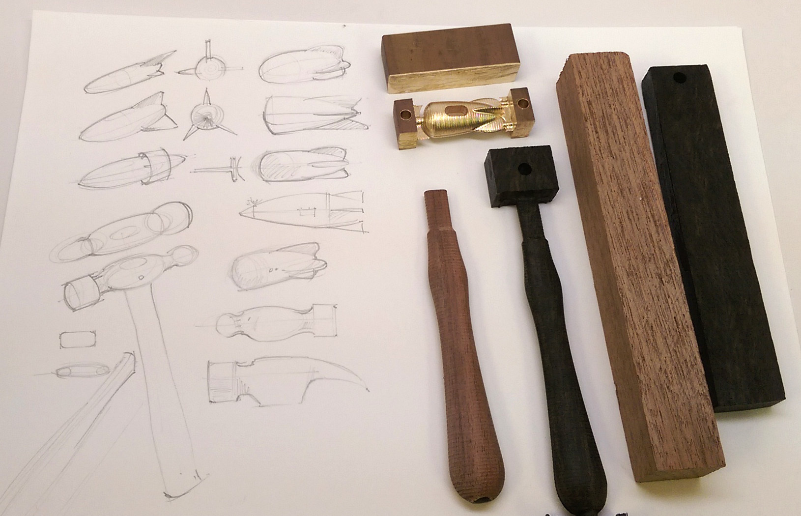
Concept Sketch and First Cut Prototypes

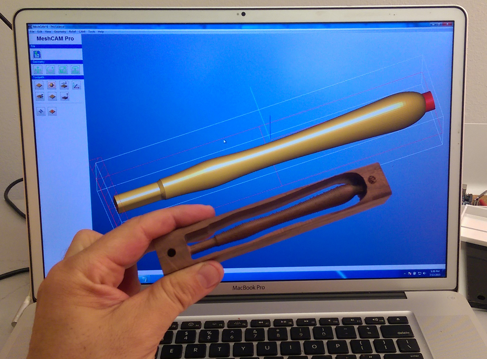
Work in progress - Walnut and Ebony handles with the Retro Rocket Hammer head.


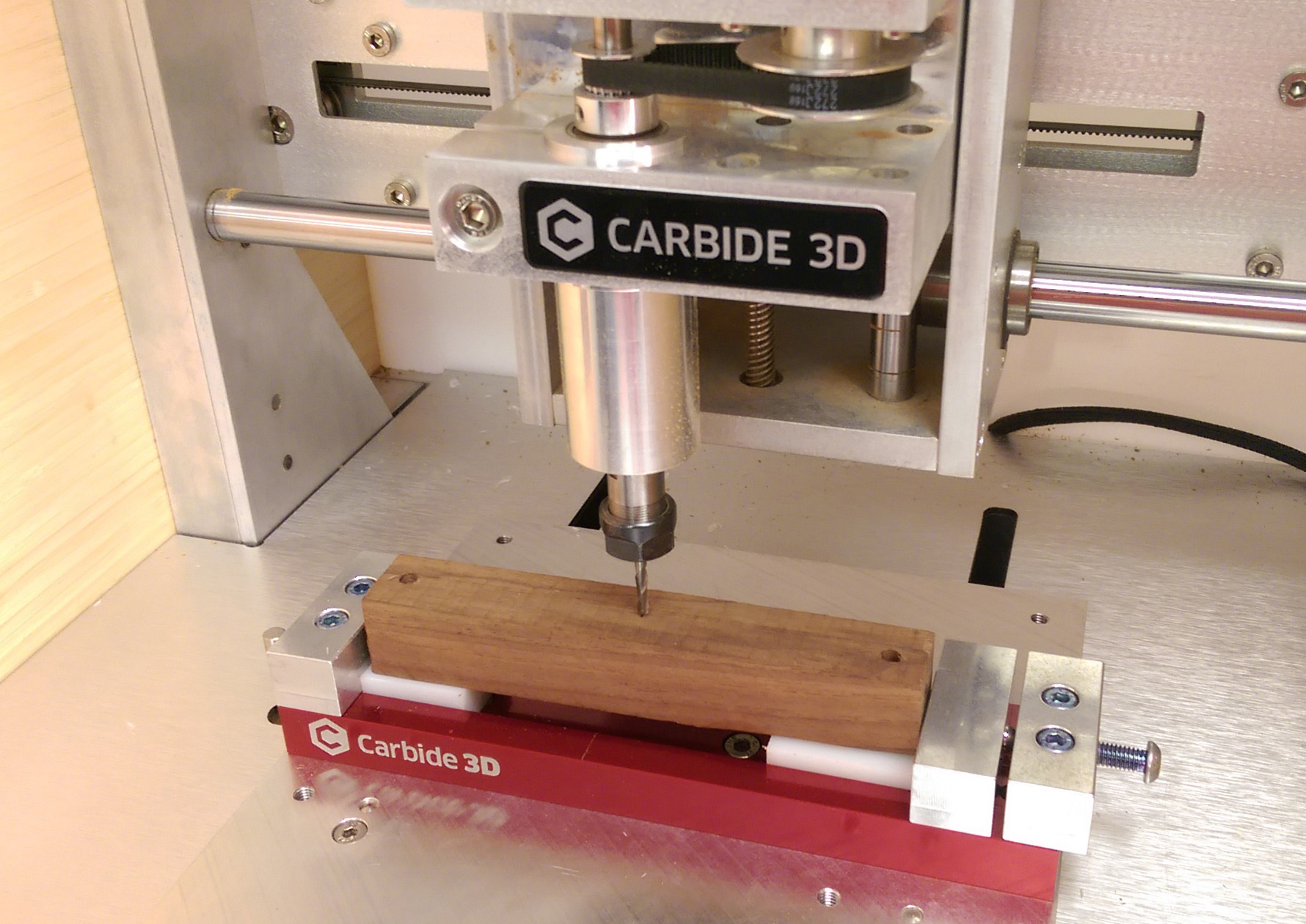
For the wooden Hammer Handle - I used the Vise inner channel to locate the Blocks with 4mm Pins, Im happy to see people making use of this solution. It does have its limitations, Compression from the vise jaws will bow the work if you lose too much structure for example.

The Compression issue was avoided here, as you can see I kept a frame around the handle by cutting the geometry only.


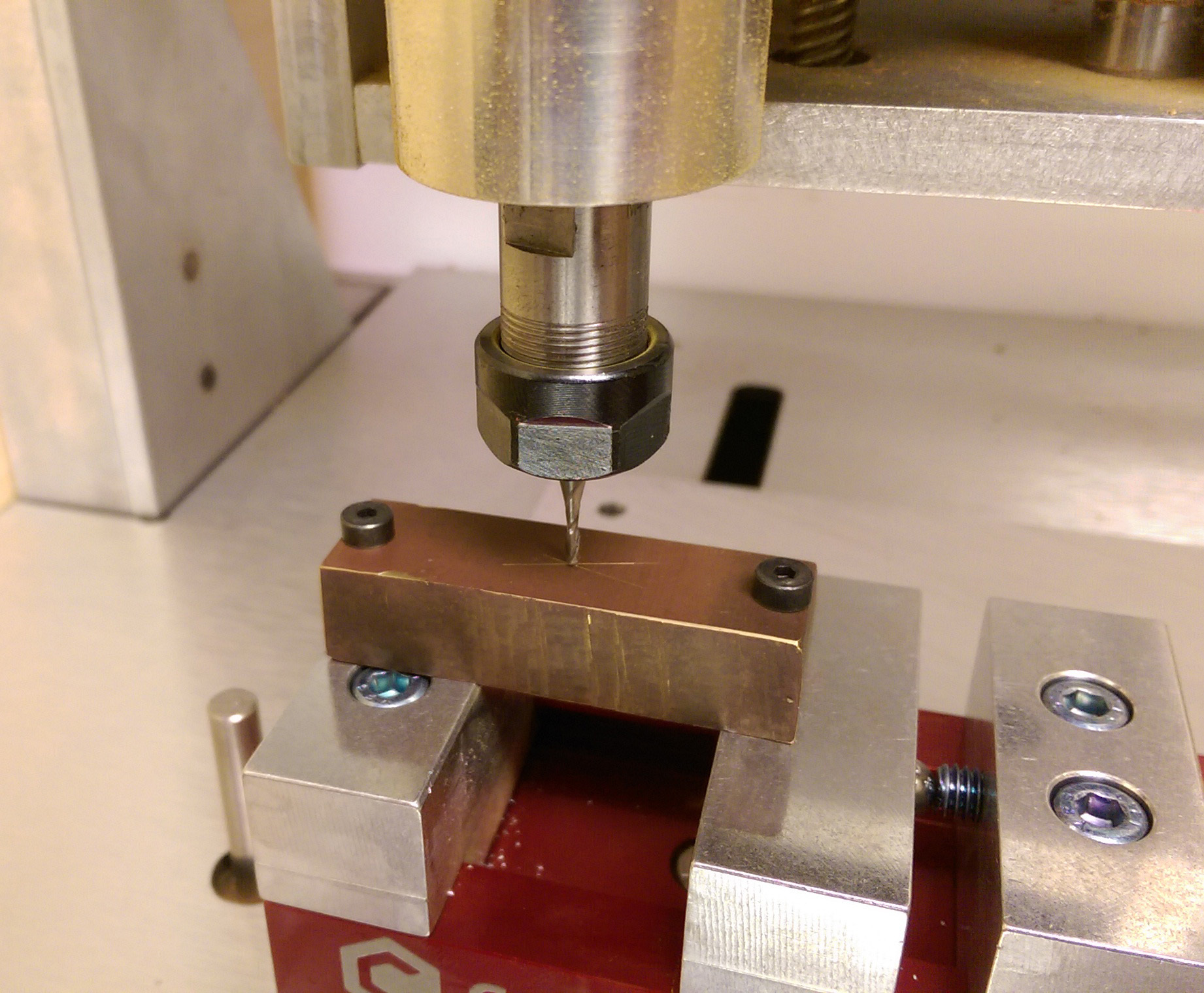
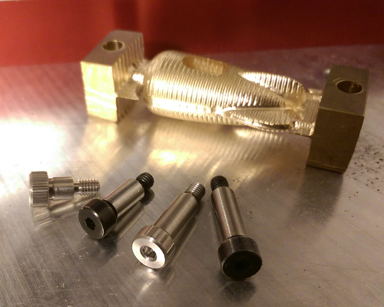
Now on to the Brass, and my approach to holding the material for the 2 sided machining.
Using the Rapid to centerline position in Carbide Motion, I can ensure that I can repeatedly use my new modification to the Vise. I used the Nomad to Drill 2.5mm holes in the top of the jaws, then I hand tapped them with an M3 tap. McMaster has a variety of Shoulder Bolts, I ordered several lengths, but the beauty is they have a 4mm shaft, so I drilled 4mm holes in the brass stock in the drill press, but it could be done with a .125 cutter also.

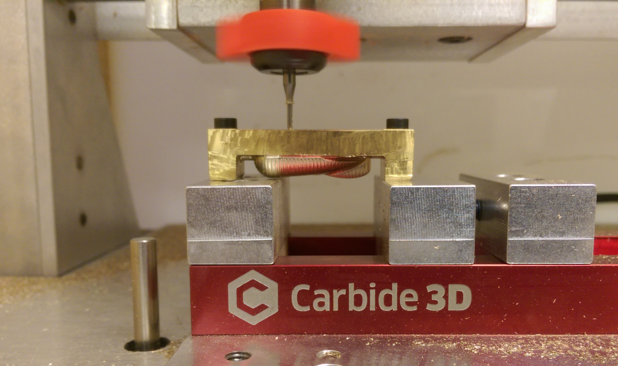
I want to take a moment to acknowledge the FANtastic collet add-on seen here and made by COOKIEMONSTER- a Big thank you for sending us one to test, and please give us an update on the development and availability, its very helpful for clearing chips out of channels, and keeping the work clear so I can document jobs.

Rob adjusted the settings of the forum so we can share toolpath setting files and meshcam job files ( .tps and .mcf files),

but It may take a few hours for the settings to actually change.

UPDATE:

Im pretty excited about this, should make sharing tips and files a lot easier.

3D Brass settings are available for download now.

In the tool path window, you can now load these settings directly into meshCAM

-Apollobrass 063 3d.tps (2.1 KB)

7 Likes

is that a collet fan?

Yes, it was a gift from another member here on the forum: Cookiemonster. It works great!

2 Likes

The shoulder bolts I used to flip the brass rocket are very useful for work holding at this small scale. Shown here are M3 threaded, 4mm diameter shoulder bolts from McMaster in 6, 10, 12, and 18mm lengths. They are also available in larger sizes and sae threads.

2 Likes

great project and tips. i’d love to have a go at a collet fan, how is it held onto the collet?

The Fan slides onto the collet nut, and is a friction fit.

1 Like

I love this locating solution. In practice though, threads and how they seat isn’t repeatable. Maybe on the order of a few thousandths, which might be ok for your application.

For better repeatability, put a small counter sink in the vice holes, so the sides of the bolt shaft contact against the side of the countersink. This should be just as accurate as a precision pin, which is about as good as you can get.

I may do this on my vice, but instead put two countersunk threaded holes on each of the two fastened end pieces, rather than the slider in the middle. Since the slider has some slop in it.

2 Likes

I was actually surprised how well it worked, I am contacting the stock at the head of the bolt, so it solved my challenge of part retention . I’d love to see your approach.

The trick is to use over-long shoulder screws, and ream a short hole in the vise/toolplate with threads beneath it. The tip of the cylindrical body of the shoulder screw does the locating and the threads just hold it down.

There are also “hollow dowel pins” that you can use for the same purpose–matching reamed holes in the workpiece and tooling with concentric threads below the reamed hole. If I remember the hollow dowels we used (several employers ago…) were 1/4" diameter and the screws were 10-32. Here’s an example illustration from Driv-Lok

2 Likes

Randy, thanks for clarifying. Very well said guys. Your saying create a precision pocket in addition to the threads to secure the shoulder bolt shaft in the case of lateral forces, as well as initial alignment. Which is much more accurate and proper than relying on the threads alone. In other words the shafts of the shoulder bolts should be longer than the height of the stock and seat into the vice jaws in this case. You guys are great.

1 Like

Precisely! (Pun intended).

1 Like

Hey, you’re great for doing this project, Apollo. I also think “retro rockets” are cool. And I see what you did there, tapped holes right into the vise jaws! Like a boss. :thumbsup:

1 Like

Hey, just curious - how accurate would the repeated seating be if you used used a chamfered hole and used the bevel from the head of a flat head screw to locate the stock? That seems like it would be pretty good, no?

The chamfered/tapered hole itself would be a pretty good locating feature, but the problem is the same.

If I’m thinking about what your suggesting right, you’d have a through hole on the workpiece with a chamfered feature and fasten a flat head screw into the threads on the base. The screw would be located relative to the workpiece, but not the base, as the threads are still not guaranteed to seat perfectly concentric.

Oh, I see - I feel dumb now; the problem is in the screw->base interface.

I’ve experienced this first-hand when bolting directly to the base. I thought it would be a lot more accurate than it was, (although I wasn’t using a straight bolt, not a flat head screw). You can see pictures at this thread.

I’m mentally designing a multi-screw flip base for this same ring project, with the hope that the multiple errors will cancel one another out.

With multiple screws, you’ll get a standard deviation effect. The more you add, the smaller the deviation. But, there are usually other factors that come into play with flipping a workpiece and perfectly aligning it. Namely, you have to ensure the top and bottom are perfectly parallel too. Otherwise, when you clamp it down, the second machined side will be a little skewed as it forces that bottom face flush against the table/base.

The Carbide flip-jig is great, because it takes care of all of the alignment issues for you with parallel machined surfaces on top and bottom and locating pin features that go right into the y-table. The workpiece can be any shape or size, just as long as it fits inside and doesn’t move.

@CookieMonster that collet fan looks awesome! Is it something you sell? Any info would be great. If you have a link, please post it, I’m sure there are several of us who might like to have such a thing…

1 Like

Agree, interested too in the fan :slight_smile:

1 Like

Hey, in this picture: http://community.carbide3d.com/uploads/default/original/1X/318f513af444ffd2dc10a85817d32820348d1fc4.jpg you slotted some blocks in the inner channel of the vise to locate your stock - do you have the dimension of those blocks (particularly the width)? I’m measuring about 28mm - just wondering if you had a more exact measurement to get those in super tight…

And I was curious - it looks like in that image the pins are being used to locate the stock in the Y axis in addition to providing the compression force to hole the stock steady (along the X axis) - that is, the vise jaws themselves don’t contact the stock - the jaws are pushing the plastic blocks together, and the pins on the blocks hold the stock. Is there a reason for that? I was considering using the plastic blocks solely to locate the stock in the Y axis, and then (by not having the blocks extend outwards so far in the X axis), simply holding the stock directly with jaw pressure… Would there be a good reason not to do this?

Thanks.