4 axis for Nomad

After havig the kids gripe at me about swiping their bricks, I went on line and bought a box full of black ones, a large flat and and a split flat on a drawer…no more griping-well, at least not when I am buildiing a molding container…i didn’t get all the silicone off the last time…

2 Likes

Shouldn’t you be using the S03 or Nomad to make your own Lego bricks?

NO you didn’t! Yes you did! That’s just cold! I bought these several years ago…If I were to need more, like every self respecting Shapeoko owner I would use the Shapeoko to make molds for viton orings and aluminum legos to put them on-since Aluminum fdoes not have the flexibility of the plastic used for legos!

A true independent forth axis is not supported by the GRBL controller.

Grbl is for three axis machines. No rotation axes (yet) – just X, Y, and Z.
(from: Home · gnea/grbl Wiki · GitHub )

If a rotational axis is needed, one of the linear must be given up for it, unless you go the custom controller route. The options are pretty much deriving a rotational axis from an existing liner one (as described above using rack and pinion or similar) or disconnecting a liner axis and using that control channel for a rotational axis. Generating G-code to control this would be… interesting.

I would not be surprised if a forth axis shows up in Grbl fairly soon, as there is a fork for the Mega2560, which is much roomier memory-wise, and has many more I/O pins available.

2 Likes

4th axis does sound interesting but as always limited Z height on the Nomad makes it not as useful as I would want. Thinking about making an incremental rotational mount (for a workflow along the lines of Apollos 4 sided flip jig) so I can mill faces at different angles. If one was incredibly clever I suppose one could build an interceptor box that sits between the GRBL controller and The gcode sender to handle the 4th-axis but this seems like a bit more work than I want to do for a 4th axis which I don’t absolutely need at the moment.

1 Like

The limited Z height is less of an issue that one might think, given the overall small envelope of the machine. For a horizontal fourth axis parallel to the X axis, I would put about 60mm as the largest practical diameter of a workpiece, and length is likely to be limited to maybe 150mm, given that the axis would need to mount on the moving table.

Replacing the Y axis with a (horizontal) rotary axis, to make a cylindrical coordinate system with radial tool and keeping the system a 3-axis total, would allow the table to be removed, giving a maybe 10mm more diameter and a full 200mm length for a part. I don’t know if there is enough room to meaningfully replace the table with a vertical axis rotary table, to make a cylindrical coordinate system with the tool axial, and maintain good rigidity, and I really don’t know why one would, as the g-code would be a bear to generate, and maintaining appropriate feed rates would be difficult.

But I don’t think I’ll worry about it much more, as machines are available that have the native ability. On the other hand, maybe I’ll build setup to replace the Y axis at some point just for giggles. I probably have sufficient material and parts stock to do it for no more than the cost of the stepper and some time.

3 Likes

I gave a passing thought to making/buying a lathe indexing wheel and rotating it by hand to the next notch before engaging the CNC. But I don’t have a project that calls for such an experiment so I haven’t spent any more time with it than just wondering if it would work.

2 Likes

I’ve been wanting to do/learn this, myself.
I’ve seen where a lot of folks just remove their floor/wasteboard to reach some oversized parts, stumps, bowls, etc…
I also saw a commercial 4th axis router, kind of similar to this:

But not exactly, and it gave me the idea to mount a 4th axis under the waste board, off to the side, but under the work envelope.
I have an old mini lathe that I want to do that with. Just add a stepper drive to my spindle, and mount the spindle’s center even with the top of the waste board.
Sorry, I didn’t see this was for Nomad.

2 Likes

I hadn’t thought of that.
If the circumference equaled the same distance as a flat picture, and you made an index wheel with the same number of notches as the stepover of the milling bit, and you moved it one notch per pass.
Cool.
Now that I’m thinking about it. If the index wheel has the same indexes as passes, then the stock size wouldn’t matter. It would be a way to scale up/down a carving.
I hope I dont think about this all night. I can get confused easy :slight_smile:

2 Likes

My thought was to cut the top, rotate the stock 90 degrees and cut one side, rotate again and cut the bottom and rotate again and cut the other side. This is kind of like the method for doing carving where you use a bandsaw/scrollsaw and cut the outline on the top and side and then blend the edges. A nice thing about an indexing wheel is that since the stock never moves in the x, y or z direction, the origin stays the same for each face you’d need to cut. Again, I don’t have a project I want to do to be able to test something like this. Combine an indexing wheel with some 3D modeling (which is way beyond my current skill level) and I believe there could be some interesting stuff produced. I think about this kind of crap all the time. I’ve been thinking also about a rotating wasteboard (I can’t imagine an application for that, but that doesn’t stop me from thinking about it) and another project in mind is to mount one of my lathe chucks so I could do engraving on items like checkers and mahjong tiles

1 Like

I think about this kind of crap all the time. I’ve been thinking also about a rotating wasteboard (I can’t imagine an application for that, but that doesn’t stop me from thinking about it)

Here’s an application: Recall the discussion several months ago about curved tags ( Engraving text on to brass? )? A curved wasteboard and rotary setup would make that a snap, as there would no longer be the need to match curvature in generating the G-code.

1 Like

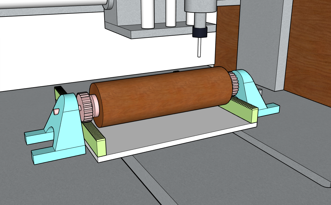
I recently made a 3D model of the Nomad (3D Model of the Nomad 883 Pro), mostly so that I could follow it up with this idea of a rotary axis based on the Y plane, as Will describes.

I could probably machine all of the parts required on the Nomad, but would be grateful for any practical advice. My first concern is being able to clamp firmly while allowing free rotation. Has anyone attempted this already?

7 Likes

It’s been done for other machines, as noted on the wiki.

Hopefully I’ll find time for it after I finish up some other things.

So, with that gearing you could attach the “feet” to the back of the cross member for the x/y motors (moves on the Y axis) so when the y axis moves, then the cylinder turns.

Hi all,

I just wanted to share results of my simultaneous 4th axis project for my Nomad 883, catering for maximum stock dimensions of 70mm diameter, and length 150mm, see video below.

https://youtu.be/IyGrrUfpbOA


The project involved:

  1. Adding a custom designed 4th axis mounting plate onto the Nomad baseplate. The unit shown is plastic, but I’ll explore upgrading this to aluminium.

  2. Adding a 4th axis stepper motor, headstock/tailstock combination (purchased from eBay). The stepper gearing, along with the controller’s microsteps provides high precision – theoretically 0.03 degrees per microstep. I haven’t measured the actual backlash yet, but no indication it’s problematic.

  3. Replacing Nomad’s main controller with an alternative, the Super Gerbil CNC controller. It uses extended grbl that supports simultaneous 4th/5th axis. I’ve retained the existing Nomad spindle controller for now, and drive it from the Super Gerbil’s PWM output. Controller-wise, it’s easy to upgrade the spindle, but first I need to work out a really solid mounting to the Nomad’s Z axis.

  4. Replace Carbide Motion with an enhanced version of UGS (Universal Gcode Sender) that includes support Super Gerbil related features like mist, 5 axis etc.

The Super Gerbil kickstarter addresses points 3 and 4 above, and is now live: https://www.kickstarter.com/projects/2118335444/1112157454?ref=592500&token=88705198

Looking forward to your feedback on this 4th axis project… if people are keen I’d consider running an additional kickstarter to provide the 4th axis hardware for Nomad (ie. points 1 and 2 on above list)… please click the heart symbol for this post below ( <3 ) if you’d support this.

Assuming you have all the above components, the installation skill level is low to medium.

Cheers
Dan

8 Likes

Awesome. I was just checking out Super Gerbil last night on Hackaday!

Is tool length probing already supported?

Hi Phil,
yes, the Super Gerbil has an input terminal for probes, am setting it up to work similarly to the Nomad.
BTW, am creating more videos on my youtube channel - let me know if there’s anything in particular you’d like to see.
Cheers
Dan

1 Like

Wow! Good job Dan, that blows my idea out of the water! I look forward to seeing your results.

I wouldnt mind a closer look at the board install and wiring at the back but thats more of a picture request than a video request. The more the better!

Hi Phil and Everyone,
just re-posting this photo after the forum data loss…


The unconnected plug labelled ‘FRONT’ is simply the Nomad’s front button which wasn’t wired up at the time of the photo.
I’ve also just completed another CNC upgrade - this time a 3020 rather than our Nomad. https://www.youtube.com/watch?v=G_9dc0BAf0M
Work is underway on tweaking and testing this physical 4th axis design, but our controller Kickstarter is above 50% now, so we need everyone’s support to get us there… it’s no use having a physical 4th axis if you don’t have a suitable controller :slight_smile:
Cheers
Dan