4-Sided machining?

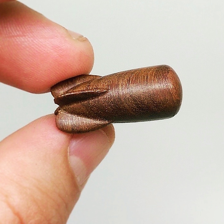
So, I’ve been making my first tentative steps into 2-sided machining with the Nomad and MeshCAM. I decided to use a simple model of a classical-looking rocket.

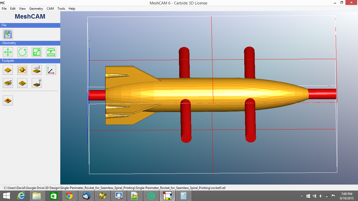
Now, this model has one glaring flaw for a 3-axis machine: the “pods” on the fins. The Nomad obviously can’t do the undercuts, so the Z-aligned fins were going to end up not quite right. But that was okay, I was just doing this for tryout. So, I loaded my low-profile vise (not having a flip jig yet) with one of the little 1"x2"x3" cherry-wood blocks from Carbide, aligned the longest dimension of the wood with the X axis of the Nomad, and started cutting.
But… while doing this, it occurred to me: if the stock were symmetrical around the Z and Y axes, I could conceivably just keep rotating the stock 90deg around the X axis, and keep running the NC file, and eventually achieve the rocket, complete with undercuts. Heck, if I was feeling adventurous enough (but not this weekend), I could do it with the stock I had, just by doing separate NC files for when the 1" and 2" dimensions of the block were aligned with the Z axis.

But that got me thinking (uh oh). As long as I can zero properly on each face of the stock as I rotate it, I could conceivably do 4-sided (or even 6-sided?) machining of complex, non-symmetrical models, limited only by the precision of my zeroing… and by my ability to prevent the 3rd-face and higher cuts from interfering with the supports left during the 1st and 2nd-face cuts. Darn, I knew it was too good to be true.

Still, the idea won’t let go of my imagination. Just brainstorming off the cuff, here, but I imagine the critical bits would be:

  1. Being able to center the model in the stock exactly the same way, at every rotation
  2. Modelling the supports into the model itself, rather than using MeshCAM’s semi-automatic supports.
  3. A really good way to repeatedly zero the Nomad to different faces of the stock. This is probably a solved problem, mostly, given other forum discussions, but I imagine that very flat-sided, very squared-off stock would be pretty critical to making this actually work well.

So… am I actually onto something here, or is it just the sleep deprivation talking again?

3 Likes

The G code world of CNC defines three rotations - A, B, and C which correspond to the X, Y, and Z axes.

Yes, there are machines which also allow such rotations. Do a Google search for “5 axis CNC” and look at some of the videos. Look for “CNC 5 axis impeller video” and you’re in for a treat.

The machines capable of 4 and 5 axis work are, as expected, more expensive than 3 axis machines. Now one has to deal with bending and flexing WHILE rotating. This, however, isn’t really the challenge - the CAM software is. It gets seriously complex to implement, maintain, and ensure quality of the machining.

Four and five axis work can be performed two ways - indexed and continuous.

Indexed machining is indicated by 3+1 (4 axis) and 3+2 (5 axis). Conceptually, one is still doing 3 axis work but one can tell the machine to rotate around one (+1) or two (+2) axes to fixed points (angles) - indexes. Indexed machining allows working on 4 and 5 sides of stock without a human to move the stock. This makes it valuable in cost reduction. The software for this isn’t usually too expensive because the machine isn’t rotating while it is machining.

The two sided machining that MeshCAM implements is a form of 3+1 one machining - you’re the rotator and only one index is allowed (180 degrees)!

Continuous machining is where things get get really, really complex. One can now machine stock by moving in 3 dimensions and in one or two rotations AT THE SAME TIME. It becomes possible to machine shapes that cannot be done in 3 axes, even with a two sided flipping.

The math and calculations to deal with this rapidly goes beyond what a human can do, at least in a practical amount of time.

In continuous 4 and 5 axis machining one can ensure that the position of the tool can maintain optimal positioning - even if one is machining a curved surface. A simple case of this is “perfect normal” machining. The normal of a surface is the optimal perpendicular of the surface at the point it is evaluated with (this is complex math stuff). One can now machine something like a sphere attached to a circular rod from a piece of stock.

Different types of machining become possible, not just “perfect normal” machining. Now there are tens of ways to deal with machine a surface and the feeds and speeds can become complex. The CAM software has to handle a lot of things to make it easy for a human to hang onto what is going to happen.

The calculations to handle moving around 3 axes and one or two rotations at the same time is… pricey. Some of these packages are are $15K, 25K and even $50K, and the yearly cost of maintaining them can run into several K per year. Even on a “sale” one of the best packages goes for around $7K (for a single copy) and ~$3K per year for maintenance!

Why all the expense? Because these packages take over for a human and automate the calculations. The more they take over - more autonomy - the less the human has to do and the machining expense drops. Many of the multi-axis types of machining are practically impossible for a human to handle - there are just too many calculations to be done by handle.

I’ve been around 3, 4 and 5 axis machining for quite some time and I can tell you that that you’re right on the money.

Your on the right path. Keep going!


This rocket was a 2 sided operation, and I used pins to rotate accurately - similar to the lego blocks video. My next test is to try the 4 sided approach using pins. However, as you have described - having perfect stock and rotating in the Vise should work.

2 Likes

IMO you should not have to rezero after each rotation if you are doing it right. You don’t want to do that, really.

Define the stock as symmetrical and run the calcs on each facing. Maybe use a depth of cut limit if it makes sense.

oh you could also do that rocket as a 2-sided by flipping on a short axis. assuming it fit within the z pocket

Can you machine it using two files/setups? The first one would be a two sided model which cuts two fins thicker without the pods. The second file would be a two sided model that cuts just the two fins that were machined thicker in the first model.