Hello! I own a shapeoko XXL and I haven’t been quite able to get it working properly. Actually I have terrible accuracy problems 0.6-0.8 mm in the X axis and up to 1 mm in the Y axis.
Here is the thing, I have checked everything I know that could possibly give me this error:
I have rebuild the entire assembly and checked it is firm and sturdy.
the V wheels are tight enough to prevent unwanted motion.
The machine is squared.
I have adjusted for belt tensioning in the GBRL.
When I test my steps/mm in the air everything seems on spot.
The problem appears visible when cutting a square piece of plywood 50*50mm, the dimensions I get are totally off, up to 1 mm.
I use carbide create for the gcode and use very conservative settings.
Please if someone had this problem on their shapeoko XXL I would highly appreciate any tips or solutions I might be able to check.
does this happen at the same level or error (0.5 to 1mm error) when using the factory default settings for the Shapeoko (as set by CM when you do “Send config data”) ?
did you also check on each stepper motor that the set screws are properly tightened, with one being aligned to the flat on the shaft ?
can you share your cutting parameters (feeds and speeds, type of endmill, how much stickout) as a double-check?
do you get the same error when manually jogging over a tape: check out this method. It will tell us whether the issue happens only when the machine is under cutting load.
Hi Julien and thanks for the taking the time to reply.
Let me answer your questions and add some more details of my problem.
-yes, when I use the default factory settings I also notice the accuracy problems.
-yes, the stepper Motors set screw seems properly tightened.
I am using a 1/4 inch flat endmill with about 35 mm stick out.
Depth per pass : 2 mm
Feesdrate: 1600mm/min
Stepover : 2.8mm
Plunge rate : 300mm
RPM: DeWalt router dial 3
the problem appears only when cutting under load. I have tested the accuracy using the tape technique and my accuracy is great. Under 0.1mm
During my cutting test I am trying to make a square pocket of 5050 mm and a square piece 5050. The stock is plywood 18mm thickness.
The results that I get are an oversized pocket: 50.650.9
And an underiszed square piece: 49.248.9
The margin for error is not consistent and my Y axis is slightly worse than the X axis.
When I try to adjust my steps/mm according to the pocket values, my square piece gets even more shrinked and the other way around.
I think I have some deflection problem somewhere but I can’t seem to find where it comes from. My workpiece is very tightly secure and my belts have being re-tensioned as per the instructions manual. Also like I said my V-wheels are tight enough to ensure there is no wobble.
Any recommendation is welcome at this point, I have tried everything it occurs to me that might be a problem.
Indeed those feeds and speeds and depth per pass should not be a problem.
Since these dimensional errors appear under load/while cutting, I can think of the following potential sources:
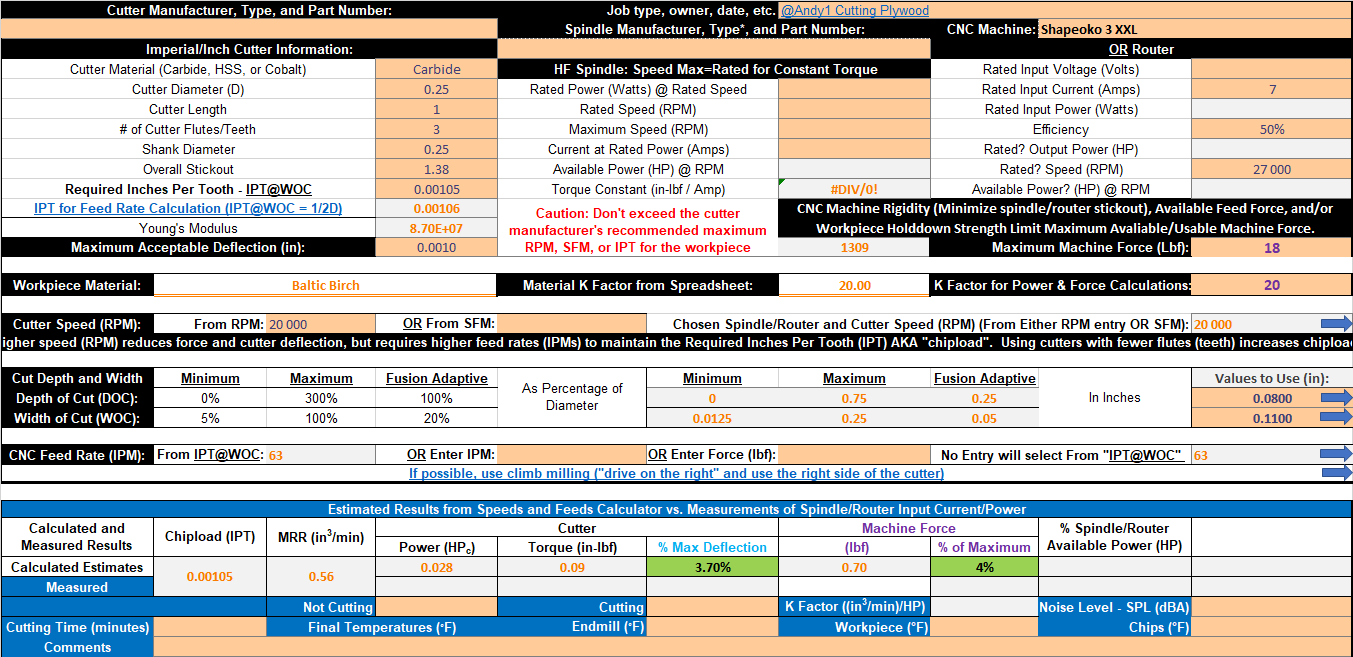
deflection as you mentioned. But I doubt it is the case here: a 1/4" endmill with ~1.4" stickout at those feeds and speeds barely deflects at all, which I verified using @gmack’s worksheet:
You seem to have an error of 0.5mm, that could be caused by a runout of 0.25mm (on each side).
0.25mm (0.01"). That’s a large runout to have, but it’s possible.
If you have a pointy bit (eg. V-bit), insert it in the router collet and turn it manually, check if the tip makes any movement (0.25mm runout would be visible to the naked eye I think)
Can you measure the width of the slot you got while cutting the square piece ? This is a good indicator of runout
tool diameter. Sometimes, the endmills are not the size we think they are. They can have a slightly smaller or slightly larger diameter. This results in similar effects as runout, so it could contribute to your problem. It’s not easy to measure, but you can try and verify your endmill diameter with a caliper (carefully, to not damage the flutes).
Could be a mix of a severe runout, a larger-than-1.4" endmill, and the residual error from the steps/mm factor. Or maybe some much simpler explanation. Sometimes when I go and make these convoluted assumptions, within 5 minutes someone posts a one liner with the actual simpler root cause. We’ll see
Have you checked that the machine is in fact square? Are your cut pieces 100% square with an accurate corner to corner measurement? I’d strongly recommend putting a new battery in a caliper, and measuring corner to corner on your cut piece - if the machine isn’t square, it will be shorter in one direction than the other. If you don’t have a digital caliper (or an old school dial caliper…and know how to use it!) get one, it will save you a lot of effort. A ruler isn’t good enough for this exercise.
Endmill deflection (which depends on its “stick-out” from the collet) is always going to be a lot less than the overall cutting deflection, which depends on overall machine rigidity and stick-out.
I proceeded to loose all the bolts of my aluminium profiles, the router mount and the V-wheels.
I followed the video made By Winston Moy and use his techniques to square my spindle.
I also added a small shim on my gantry which i didn’t have before (for squaring the gantry)
Last I re-tensioned the belts and load the default GRBL values.
I ran the same test I did before and cut a pocket 50 x 50 mm and a square also 50 x 50 mm.
*I did measure my end-mill to make sure it’s of the same diameter as advertised and I also use a caliper to measure the final pieces.
This time I obtained more accurate numbers:
Pocket: 50.4 x 50.4 mm
Square: 49.68 x 49.62 mm
I am happier with those results, but i think will continue tweaking some parts to try get more accurate results.
To figure out if the residual error is caused by deflection (machine and/or endmill) you could:
in CC, draw a 49mmx49mm square and use that to generate your pocket toolpath, and run it
use the original 50mmx50mm square to generate an inside contour toolpath, and run that afterwards: it will shave off the extra .5mm on each wall, which will put very little load on the cutter/machine. If your final pocket is closer to 50mm that your other cuts, you’ll know it’s something about deflection.
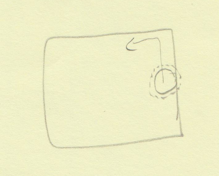
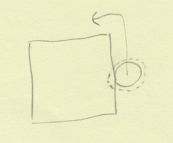
If it is deflection, another interesting test could be to cut the pocket using climb cutting instead of conventional cutting, unfortunately that’s not possible in CC (which enforces conventional cut direction). If you want I could generate a 50x50mm pocket toolpath using climb cutting for you using VCarve.
To figure out if it’s caused by the endmill runout, cut a slot and measure it (or just measure the slot you got when cutting that square). Anything wider than 0.25" indicates runout, and you’ll know by how much.
Since deflection is caused by cutting forces, you could also reduce that force by: increasing the spindle speed (RPM), decreasing the feed rate (IPM), reducing the depth of cut, reducing the endmill and spindle stick-outs (reduce the distance from the Z-axis V-Wheels to the workpiece), and/or cutting something “softer” (like MDF).
It looks a lot better. Measure the endmill - it may not be .25". at this point, you’re off by .016", which while not zero, isn’t that bad (I’ve seen way worse). That’s also really large for being deflection on a .25" endmill. That your two sides are the same length is a good sign, but I would still measure corner to corner and see if one is significantly shorter than the other.