Adventures with silent stepper drivers (and 4th axis and other Nomad electronics fun)

That is a serious like. Swappable Polulu driver boards. What are you using for a controller?

Edit - never mind - I see you are using Arduino Uno GRBL/ Arduino Due g2core TinyG

I imagine the quick and dirty would be something like a luggage scale and a dial indicator to see at what point you start losing steps.

No, I’m not using those, I’ve just tested them. I’m using Eding-CNC. I had a long look at all the options available and it stood out as the best for me.

Other options I considered:

  • GRBL: Too primitive. Doesn’t seem likely to become less primitive, as it’s limited by the ATmega it runs on.
  • TinyG: Seems to be mostly abandoned in favour of g2core.
  • g2core: Seems like beta-quality software at the moment. Maybe worth another look when they finally release the board they’ve been working on for the past few years.
  • Mach3/4: Windows-only, expensive, uses the PC as the controller?
  • PlanetCNC: Expensive.
  • LinuxCNC: Didn’t look bad but looks like a whole lot more screwing around to get it to work. Uses the PC as a controller.

Eding-CNC is very affordable (219€ for a CPUA3 + software license) and has a ton of features I consider fairly high-end (particularly its macros). It’s also very well documented.

Specifically, I went with the CNC720, which is overkill but I bought it with an eventual upgrade to a larger machine or addition of a 4th axis in mind.

EDIT: I missed stock in the list. I don’t like Carbide Motion because of its lack of documentation and hackability. It’s not treated as a CNC controller in its own right but as a closed, integrated component of a Nomad or Shapeoko. In particular, as you might have guessed from this thread, I want to replace the stepper drivers.

5 Likes

For anyone who’s interested, the new controller is now 100% up and running. Everything works. Stepper driver, spindles, homing switches, the whole shebang.

One thing I love about this new controller is that it works over ethernet. No need to fiddle with short USB cables anymore.

I decided to forgo the torque tests. Some of the drivers I ordered had short return policies so I didn’t have enough time. Plus, I’m fairly confident that unlike noise, torque will remain pretty consistent independent of the drivers used, so long as they output similar voltage/current.

I do need to tune the current though. I think 1.8A RMS/2.4A peak is too much.

Anyhow, it works. I think the next step is PCB V2. I think I want a PCB with some kind of microcontroller onboard that I can connect to the Polulu configuration pins for easy configuration (e.g. changing microsteps, config over SPI/UART for Trinamic drivers).

I have two ideas in mind on that note:

  • I could basically add an Arduino to the board and in that case I’d basically have a new GRBL board. This makes SPI/UART more difficult though because the ATmega328P doesn’t have reconfigurable pins like the ESP32. Software UART/SPI would work but I prefer to use hardware.
  • I could add an Espressif IC chip like an ESP8266 or ESP32 and make the board configurable over WiFi. In this case I could also add some handy sensors to remotely monitor various things (e.g. driver temperature, maybe voltage or curent too).

I’m curious, is anyone else interested in doing this or is everyone basically content with the Carbide Motion controller? I think my obsession with quietness could be a bit odd.

6 Likes

Excellent work.

One question, did you use the model of Trinamic with the dynamic torque and missed step detection from motor back-EMF? If so, have you tried using the missed step detection?

4 Likes

I believe those features are what Trinamic calls CoolStep and StallGuard respectively. I haven’t tried them yet because they require some configuration that I haven’t got around to yet.

The drivers that make it into my machine will certainly have both features fully configured. That’s one of the reasons I chose them.

My controller actually has a drive alarm input, so my hope is to connect the Trinamic drivers up in such a way that if a step is lost, it can be signalled to the controller which can immediately pause the job for manual intervention.

5 Likes

Minor update: I think I should change my name to “slayer of CNC controllers” or something along those lines.

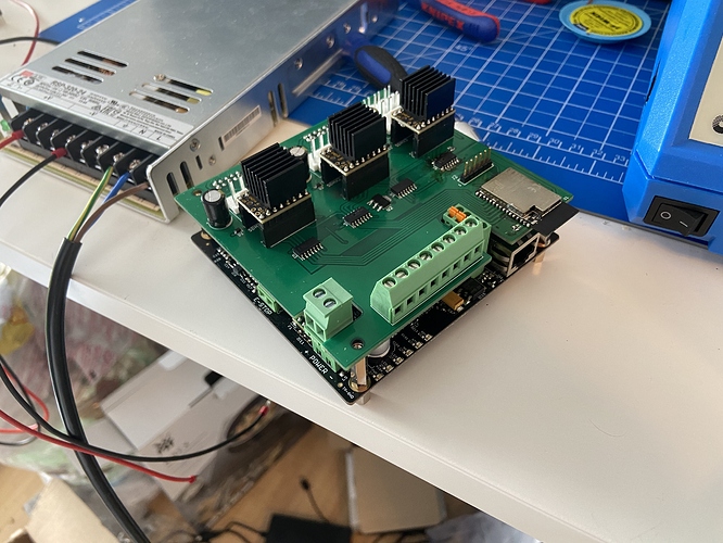
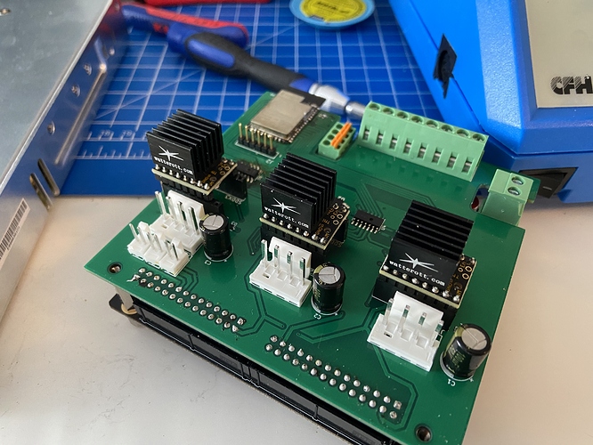
I managed to design and fabricate a functional carrier board for the CNC 720:

Unfortunately however, while I was debugging, I was unplugging and re-plugging the stepper drivers quite a few times with low visibility (this was all inside the small controller enclosure of the Nomad).

I ended up connecting the stepper driver offset by a pin, like this:

Unfortunately, on a Polulu-style driver, that means that the +24V and +5V pins from the board were connected to the two GND pins of the driver. Those GND pins are bridged on the stepper driver board, which means that I ended up connecting +24V and +5V.

All 3 stepper drivers exploded in a puff of smoke and unfortunately, though the controller didn’t explode and doesn’t show many signs of physical damage, it became completely unresponsive and no longer powers on.

I’m hoping I can get it repaired, otherwise this will have been a very expensive lesson in making sure I connect things properly.

Out of curiosity, does anyone know of 2.54mm pitch connectors that only connect in the correct orientation?
3 Likes

Ouch :frowning:
Is there one pin that is unused on those modules ? If so you could cut it flush on the module side, and put a drop of glue in the corresponding spot on the female connector, so that the module can only be plugged in the right direction and with no shift.
Poor man’s poka yoke.

8 Likes

Ok, now its your turn to explain! :smiley:

2 Likes

Ah, sorry, business lingo, it’s the Japanese term for making something mistake-proof

And by that I mean, in the early 2000’s, when Six Sigma and other Japanese business stuff was all the rage, you got extra boss points for using as many of those buzzwords in a meeting as you could.
"Sure, I will assign a Green Belt to launch a Kaizen on how to streamline that process and make it poka yoke", which sounded smarter than “I’ll fix this broken design”.

7 Likes

That’s a good idea. The two GND pins are bridged, so I could remove one of them. That would also solve the problem of inserting the driver backwards.

2 Likes

That takes care of orientation (as long as the single GND pin can take the current) but I’d also 3D print a guide that fits around the sockets to make sure the driver board can’t go in with a pin offset.

Also have to ask - whats the ESP-esqe module on the carrier board for?

2 Likes

Also have to ask - whats the ESP-esqe module on the carrier board for?

Not just ESP-esque, it’s an ESP32-S2-WROOM.

It’s hooked up to all the configuration pins of all the drivers so that I can reconfigure them at will in software and most importantly, so I can interact with the drivers over SPI and/or UART. These drivers have a ton of configuration options available through their serial interfaces. There’s also a bunch of useful status information, like how much current is currently going through the motors and how close the motors are to stalling.

I’d really like to record those stats so I can watch them while the machine is operating and see whether particular cuts are particularly hard on the motors or anything like that.

I’m also curious whether the driver can tell the controller that it lost a step and have the controller compensate.

If I’d thought it through a bit more, the steppers also have error output pins that I could have used to send a message to the controller to pause the job. For fun, I could have the ESP32 receive the same signal and send me a notification on my phone.

2 Likes

Thanks for sharing all this! My Nomad setup is also sensitive to stepper noise. In particular the z-axis tool touch-off is significantly louder than your stock video rapids.
Any chance the Uno+TMC2209s can be paired with the stock power supply and carbide motion controller? It would be great to upgrade to Trinamic drivers with minimal hardware changes.

It should be totally doable to make a PCB that that sits atop an Arduino Uno and has connectors for the stock power supply, stepper drivers and the McGillicutty board. That’s totally feasible. The reason I didn’t use the stock power supply was just that I couldn’t find the damned connector (despite it being common enough).

You could even put an ESP32 on the board like I did on mine so that you can properly tune/monitor/control the stepper drivers. Hell, you could use it to send G-Code over WiFi if you were adventurous.

As for reuse, the Carbide Motion controller board is totally out of the question. The drivers are soldered to the board and have a completely different pinout.

Reusing the Carbide Motion controller software might work but I’m not sure. I think the Carbide Motion board has a different USB vendor/product ID to the Arduino Uno and I think Carbide Motion might check that. I’m not sure though.

And minor update since I’m here anyway: EdingCNC was really helpful and is selling me a new controller at a fraction of the retail price, since I already paid for the software license on the original controller and the original controller is very much dead.

In the meantime, I hooked up the ESP32 to the stepper drivers and logic level shifters on breakout boards so I could get the software communication working properly. Communication is now fully operational. I can get status updates from the drivers at ~1kHz if I need to. If I had a faster MCU I could go even faster I think.

However I’ve shifted from TMC2209 to TMC5160. The TMC2209’s weird pulldown-UART interface was beyond me while the TMC5160’s bog-standard SPI worked without a problem. The TMC5160 should also run much cooler than the TMC2209.

Just need to wait for the new CNC720 to arrive and I can hook everything up again and start tuning the steppers.

3 Likes

It’s been a while since I updated. The replacement controller is hooked up and working happily.

I’ve been working on the software for the ESP32. I now have it spitting out metrics and logs over UDP to my laptop, which I’m using for analysis. I can now produce graphs like this:

Now I’m trying to figure out how to tune the SpreadCycle mode of the motors (the normal, non-silent mode).

Once I’ve got that done, it’s on to StallGuard (the thing that produces the “motor load” in the above graph) and then to CoolStep (which can dynamically adjust the current based on load).

7 Likes

So I ended up trying out different settings for SpreadCycle and the defaults ended up seeming to be the best.

The machine is now fully operational and I’ve actually done some cutting with it! It’s not much more exciting than the other graph but here’s some data from the machine while it’s actually doing something useful:

If I remember right, this was a contour operation so the machine was doing lots of cut, retract, rapid, cut again. The reason the green lines are so varied is that I was trying to tune StallGuard, the feature that determines whether the motors are close to stalling.

Unfortunately, I’ve hit a bit of a roadblock there. The problem is that StallGuard has a compensation parameter that changes a lot depending on feed rate. On a machine like a 3D printer where you have a pretty narrow range of speeds while printing, this is fine but on a CNC where I might be running a slower facing or contouring operation along with a more rapid adaptive operation, a single parameter might not make a whole lot of sense.

This is actually illustrated in the image in my previous post. You can see that with no load on the motor other than the machine itself, the green line (motor load) only leaves 0 (the stall value) at ~15 clock cycles per step (purple line) and only becomes stable towards the machine’s highest speeds.

I still need to play with it and see if I can find anything but I might actually have to make the ESP32 a bit smarter. Worst case, I can have the ESP32 monitor the machine’s speeds and dynamically update the compensation values for whatever the current speed is.

Once I do that, I can turn CoolStep on and the machine will dynamically adjust current according to the load on the motors.

Speaking of current, I started at 1.6A as that’s what the manufacturer said these motors were rated for but they ended up getting quite hot so I brought them down to 1.2A and all seems well.

And last thing on the stepper motor subject, I actually ended up turning the stepper drivers’ silent feature off. In their normal mode they’re quiet enough and that’s the mode in which they have the current-tuning feature. When the machine is actually operating, given the already quiet nature of the drivers, I think reducing the heat produced by the motors is a larger benefit than reducing the noise a little more.

And in other “messing with the machine” news:

I made a new Z-axis bottom plate for my Nomad:

This was needed because without that little notch behind the spindle, I can’t fit my 3D probe.

Was quite annoying to make. I reverse-engineered the original plate by removing it and using the 3D probe with the two Z-axis rails hanging loose. I then had to machine the thing on both sides without the probe since it didn’t fit yet. When I finished the part and tried to fit it, the holes for the rails were slightly too far apart, so I was stressed out for a bit and then realized I could just do a contour to carve out a bit of material to bring the rails closer together. Not perfect but it worked.

Speaking of probes, I installed a hot-plug interface for switching out different sensors. It has a mini-XLR socket and can accept both NPN and PNP sensors. You can see it here with my Z-probe:

Why am I using this Z-probe instead of the Nomad’s? It works with the hot-plug interface, is extremely accurate, has specs and I can use it for finding the top of stock very accurately. Plus I visited the guy who makes it in his workshop and saw it and wanted one…

And last and probably least, I 3D printed an enclosure/mount for my Meanwell power supply and attached it to my enclosure:

And bonus, here’s what the software I use on my controller looks like:

I’m quite fond of it so far.

6 Likes

Oh and I have a plan for improving the enclosure as well: I’m going to try using 6mm acrylic instead of MDF for the front panels so I can actually see inside with my eyes when the machine is running (instead of the Raspberry Pi attached to the front).

6mm acrylic should be the same weight as the 10mm MDF I’m currently using so should have similar-ish acoustic properties?

Looks great, nice progress! Would love to have silent steppers on my nomad. What 3D probe are you using?

1 Like

I’m using this one (though the better description is the manual), it’s made by the same guy who makes the Z-probe and hot-plug interface I’m using.

The most important things about it in my opinion are the adjustable mount and the relatively short overall length. It still leaves most of the Nomad’s Z-axis range operational. It also comes with really nice macros for my controller.

1 Like

Nice! I’ll keep it in mind for the future. How are you liking it? It crossed my mind to put a duet wifi on my machine to make it easier to add new hardware and also ability to readily create macros. This post made me start looking at the cnc720 controller.