Here’s a workflow for DXF. I drew a simple file
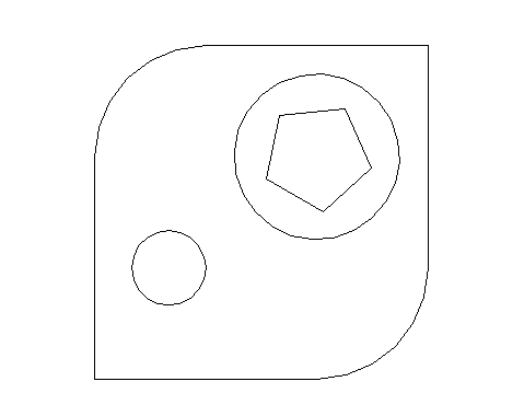
It is 2.5 inches square and has random geometry.
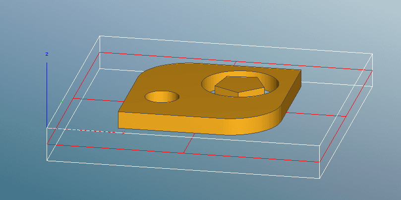
I imported it into MeshCAM at full size. I placed a stock around it that is 4 inches square and half inch deep. I told MC to center X and Y and make a top margin of 0 (i.e. the geometry is flush with the top of the stock). I set Max Depth at .25" and set the Program Zero at the top front left corner of the stock (this is where you will zero the cutter on the Nomad)
I used a .125" flat-end cutter for this geometry since it fit all the spaces to machine. As @mitchell said, you’ll need to choose your cutter size based on the size of the details you want to machine. Also cutting brass you’ll want to be conservative on your stepovers and stepdowns and machining speed to not overtax the Nomad.
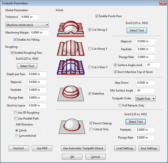
After a little calculation MeshCAM will show you the toolpaths. They are really dense here because I used a small stepover and stepdown for the roughing and finishing
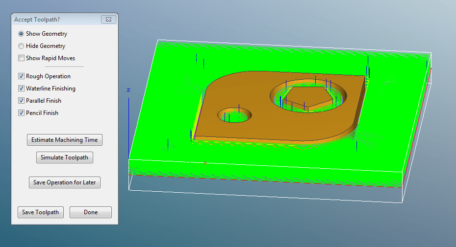
And here is MeshCAM’s simulation of the result
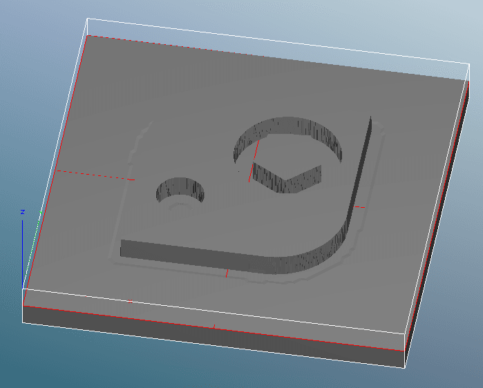
It really is that straightforward.
You’ll want to remember to mirror-image your logos since you’re cutting “from the bottom side” but you probably already do that for the current method. If you don’t mirror image them then your etching vendor does.
The important part will be in selecting the machining feeds and stepovers. @ApolloCrowe is machining brass for his retro rocket hammer head 3D Rocket Hammer Head in Brass so he can probably give advice on what will be appropriate.
And I was wrong about MeshCAM not accepting multiple-nested outlines (I specifically made an outline within outline within outline in my test DXF). I was thinking about SolidWorks which only takes a single nest level for extruding shapes from DXF input.
Randy