Do they behave any differently if you disconnect the terminals that go from the switches to the feed hold (as in the connections to the COM and NO on the switch), and just leave the + and ground for the LED (the big tabs on either side of the microswitch, typically)? Power draw for single color arcade buttons are typically 0.02A at 12V.
The circuit to draw is the one that represents your wiring; complete.
There have been a couple of really good guesses, suggestions and questions, but if you’ve somehow mis-wired we won’t know if that schematic just comes out of your memory.
It sounds like the internal LED lamps already have a current-limiting resistor that is appropriate for 12V, but the brightness is higher than the OP would like. I suggest putting an external series resistor in each LED circuit. You will have to experiment with the value, probably starting with a 1K Ohm (1000 Ohms, 1/4 watt) value, and going up or down as needed.
And yes, those LEDs are designed to be driven from 12V DC, and not wired in series.
Yes, that’s correct. The switch and LED connectors are separate.
You’re right, of course, but the wiring really is simple. The two leads from the plug-in wall-charger are connected to a terminal block, and the LEDs are connected to that, in parallel to each other. There is no mis-wiring and all the connections are secure - and I’ve just checked, so it’s not just remembered ![]() Here’s a digram:
Here’s a digram:
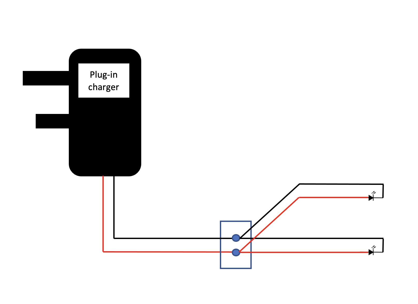
Having said that, the LEDs are still dim - and remain so when one or both are connected, sorry, @Travis54 . Also, both LEDs are white. The supplier has just responded by telling me each LED “needs 20ma” (which I suppose should read 20mA?), so I guess they’re either dim by design, or the PSU is defective.
Nope, I’d actually like them brighter. At the moment, they’re so dim (and I’m beginning to empathise) it’s not obvious when they’re supposed to be ‘on’.
1 Like
@Japi42, the terminals of each switch are connected, in parallel, to the feed-hold terminals on the board. The LEDs to illuminate the switches are from a separate, 12v DC supply.
So when you tried to only connect one, and the brightness was ok, was it also the case when you only connected the other LED instead? i.e. do they both light up normally when connected alone, but get dim when connected simultaneously ?
So, @Julien, when I first posted the question, I was unhappy with the brightness of the LED in the switches with the PSU I was using, so I checked one of the LEDs (of a different, but same model of switch) with a new PSU, and it seemed brighter. When I replaced the original PSU with the new one, both LEDs were dim.
I’ve just disconnected the new PSU from the circuit and tried each of the LEDs - one at a time - and they’re all dim. I checked again with the original PSU, and they’re all dim.
Conclusion? I have no idea why the LEDs are so dim. It’s quite difficult to see them (when ‘lit’) through the coloured button of the switch. It was my hope the buttons would be illuminated much brighter than they are. At the moment, they’re hardly illuminated at all.
I’ll see what the supplier says…
do you have a voltmeter ? If so I would check if the power supply output voltage is actually 12V once LEDs are connected, or if somehow they make that drop to much lower. Sorry if this was answered before, did not re-check the full thread
1 Like
@NewToThis Do you have a datasheet for this LED switch that you can share?
Can you find another 12V source that you trust and apply it across the LED? Let’s start trying to rule stuff out. 12V could be:
Eight 1.5V in series, two lantern batteries, one 3S LiPo battery, a car battery that’s not 100% charged (tends to run closer to 14), another wall wart that you cannibalize or adapt to, a bench top power supply, a car battery conditioner/charger…
Can you take the diffuser/plastic covering the LED off? It looks like a big red circle of plastic in the picture. The purpose is to see if the plastic is absorbing or diffusing away most of the light. If it’s an arcade button, maybe they meant for it to be used in a dim room (like most arcades), so its dim/diffuse by design.
Speaking of, what is ‘dim’ to you? Is it dim under sunlight? Bright shop lights? A softly lit room in the evening? Under darkness? I bring this up only because I’ve been fooled before by my own miscalibrated expectations (in the usage scenario).
White LEDs are also inherently inefficient because they depend on a broadband phosphor to absorb short wavelengths and re-emit the light as a bunch of wavelengths resembling white. So I wouldn’t expect nearly as bright a white LED for the same power as what you get for a blue LED.
1 Like
Yes, test the LEDs with a known-good voltage (or use a DVM to verify the voltage). And a “12V” LED lamp should have no problem running from 15V, so using a fully-charged car battery is an OK test.
LED brightness is all over the map. I’ve used some “high efficiency” white LEDs that were painfully bright at 20 mA. Modern red LEDs are usually very bright at 20mA, while the early ones were pretty dim at the same current.
By the way, I say “LED lamp” because a plain LED can not be connected to 12V – it will blow up. If you have “12V LEDs” then there is at least a resistor in series.
2 Likes
@NewToThis I’ve used similar buttons several times. In daylight or in a room with the lights on, I’d say they look like a brighter version of the color they already are.
You can access the resistor on the LED’s, but you’d have to desolder and solder in place a lower value to get more brightness. If you’re planning on doing that, make sure you measure the current draw before you do.
You could overdo it (I’m a fan of that!) with some LEDs like these. Your arcade switches could go in the center.
2 Likes
I’ve checked the voltage of the adapter and it was… 9VDC!
I’ve replaced it with a 12VDC adapter and the LEDs are much brighter (in my hand, at least) but I’ll rewire the switches tomorrow and let you know how I get on.
I also disassembled one of the switches to look at the parts and found the resistor, soldered to the LED and the wires wrapped around a former, which slots into the LED mount. The resistor has a yellow, purple and brown rings (471 ohms?), with a gold tolerance ring. Would there be any benefit in changing these?
Thank you.
3 Likes
I wouldn’t go there, unless… you are ready to burn one and have a few spares.
The resistor is 471 ohms, in series with the LED. I don’t know what specific LED model this is, but they typically have a forward voltage in the order of ~2V. So we have ((12 V - 2V) / 471) Amps going through the resistor (and the LED), that’s 20mA, which is pretty typical to drive an LED. It is possible that this specific LED could support more than 20mA, maybe 30, maybe 40, hard to say without a reference. But at some point it will go “oops, this is too much, I’ll die then”.
You may try 330ohms (the next value down the resistor scale), it would put 30mA through that LED, making it about 50% brighter, and most probably not killing it.
EDIT: the resistor you have is actually 470ohms, I failed to mention that. The third color ring is a multiplier, not the last digit. Brown is “x10” so 4 (yellow) 7 (purple) x 10 (brown) = 470ohm
3 Likes
If you want your LED to turn different pretty colors moments before it dies, increase the current very gradually. As it heats up beyond the power dissipation (P=I*V) it’s meant to handle, its color will shift to a longer wavelength. You may have seen this before overdriving a green/chartreuse LED, only to have it turn orange. Because a white LED initially emits as blue or UV, exciting a broadband phosphor as I said, it means you might be able to see it progress through the rainbow from blue to green to yellow to orange to red before it dies. It’s anyone’s guess how many colors you’ll actually get to see before the magic smoke leaks out and the photons go into hiding.
4 Likes
You’re right, I probably shouldn’t. All I needed is to for the switch to be visible in the dim light of the work-shed, and thanks for the resistor info ![]()
That’s a great description, Travis, thank you. I’m averse to a bit of magic smoke, though, so I’ll probably leave playing with electronics/LEDs for the time being, but it does sound like fun!
I can’t help it. It’s “…all part of growing up and being British…”
![]()
![]()
![]()
1 Like
So, would you believe I’ve found out what the main problem was (apart from trying to use a 9V charger) and it is…
…drum roll…
…different LEDs in the switches, for heavens sake!
The brightness of the LEDs differ in the red and blue switches, with those in the red switches much brighter. I just assume the resistors are different, but I can’t be bothered to check.
You might be able to see the difference in the photos…
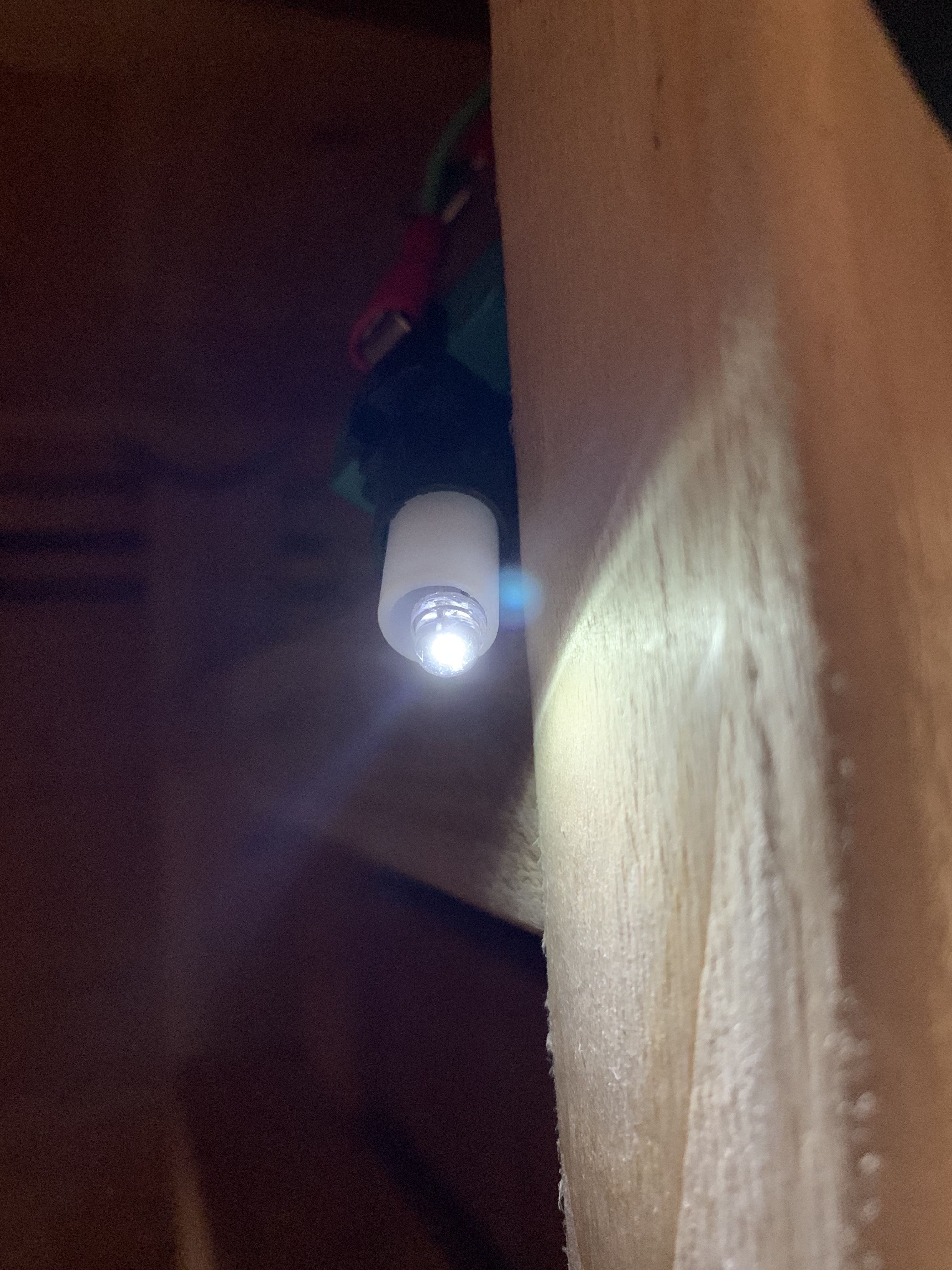
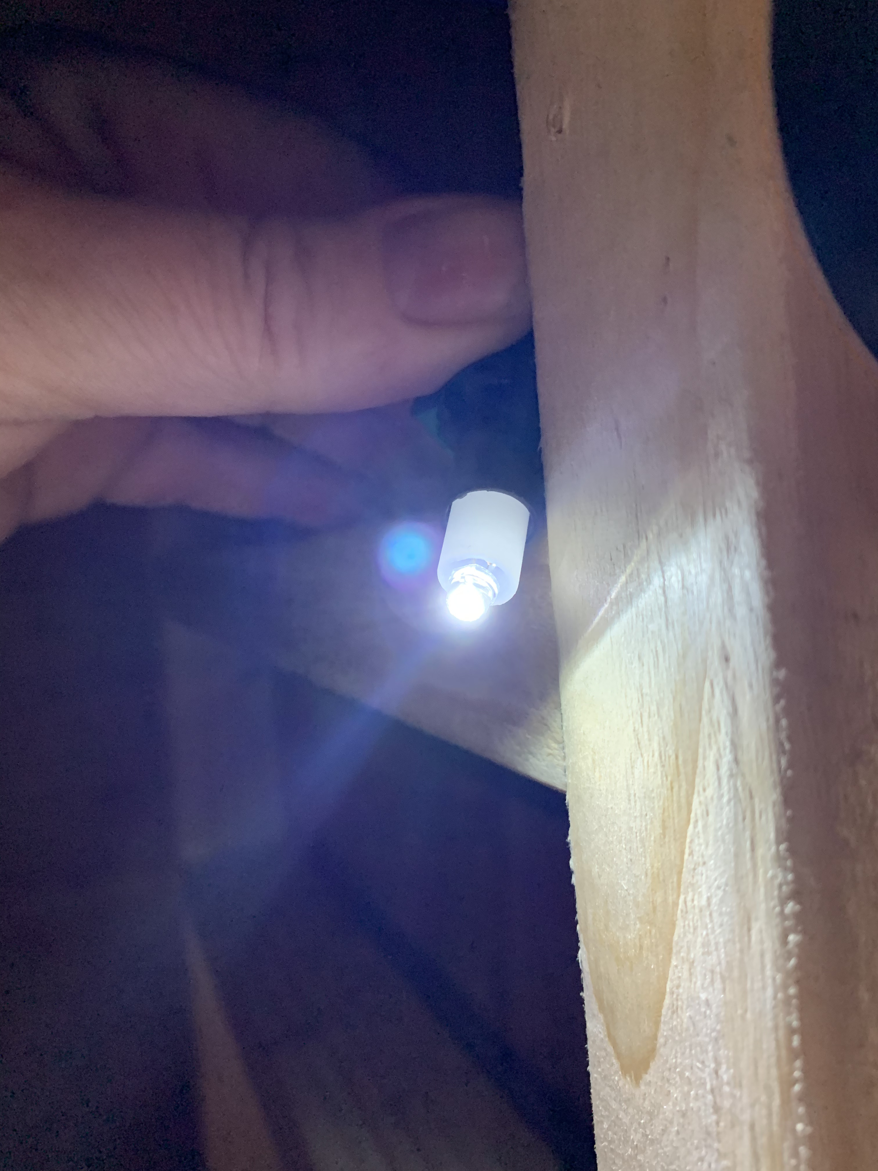
…or you might not, but they’re definitely different.
Ho hum 
I’ve seen switch manufacturers use different LEDs to get the brightness through different plastic covers (which act like filters.) I’ve changed them out for bright white LEDs often.
1 Like
This topic was automatically closed after 30 days. New replies are no longer allowed.