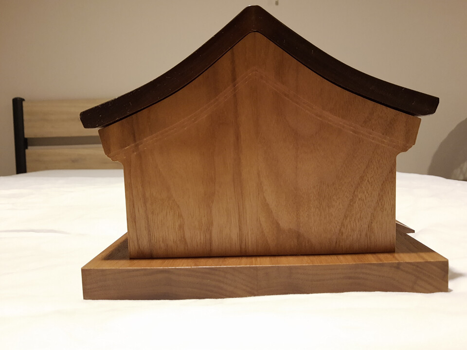
I wanted to honor the passing of a parent. I thought about a memorial box / urn; I see people put things like fishing or hunting activities, nature scenes, etc on them. I actually couldn’t think of something that really represented them. I ended up making an architectural memorial box to represent a traditional Chinese courtyard house center building. The larger window “panes” are not exactly historical, but I wanted a more open look for them (historically they are were paper supported by wooden frames).
Modelled in Fusion. I was competent in CAD before this excercise, but the CAM was all new learning for me. Machined out of walnut. “Jointed” on a table saw, but otherwise all work done on the Shapeoko XL. Ended up with a small warpage / gap on the roof lid, but oh well. The back panel has their name engraved, but I’ll omit that for privacy reasons.
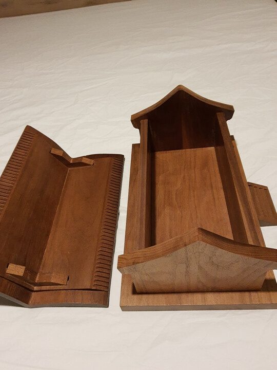
The roof has front roof, back roof, and two underside braces. I used the Shapeoko to cut the mating angle between the front roof and back roof, and cleaned it up slightly by sanding over a ghetto bench plate (granite flooring tile with sand paper taped on it).
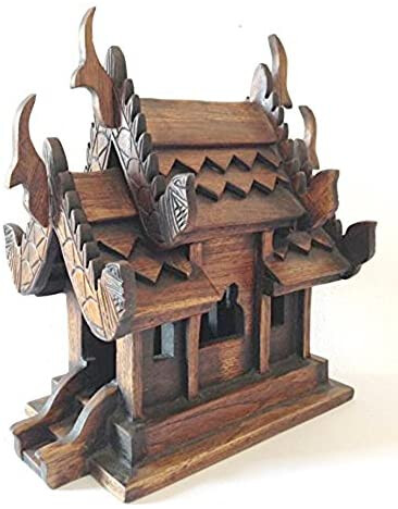
A while back my daughter went to Thailand. They have small houses in the garden that are prayer boxes. You write your prayer and place it inside. My son inlaw asked me to make one for thier yard. This gives me an idea.
What a beautiful box! I would love to see a model of the roof parts or a description of how you cut them out handled work holding (looks like it has to have been two sided?) if you have the time.
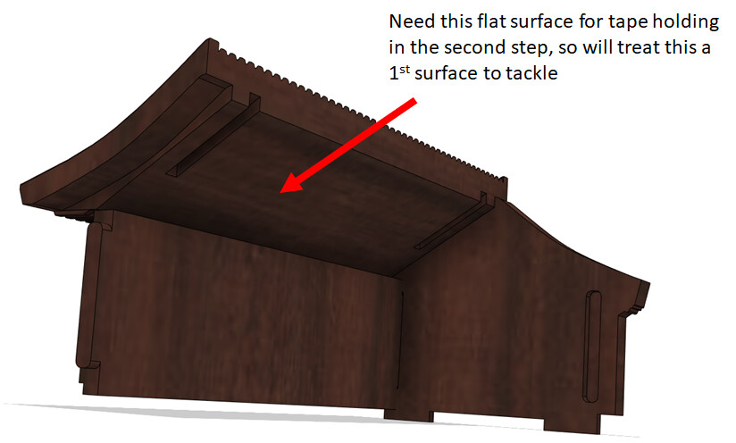
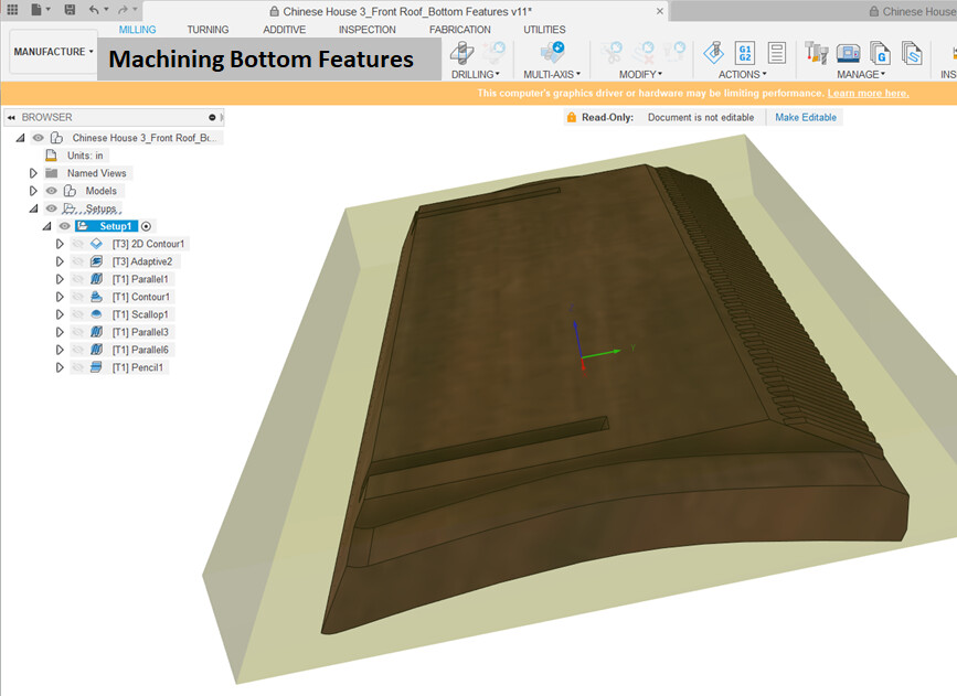
I use exclusively carpet tape. I haven’t bothered to make any clamps or such, but will eventually. After making the model, I generally make 2 separate CAD/CAM files, one that pertains to each major surface. It is not specifically the intention to make 2 separate CAD models, but it may help to suppress some features in one of the models. In this case, I suppressed the roof tiles feature when machining from the bottom (it is adequately covered by the top machining and leaving it active while doing the bottom just adds unnecessary complexity and chance of problems).
After surfacing the work piece, the first set of operations is not that critical in terms of precisely locating the work piece. This side used 1/4 and then 1/8th endmills.
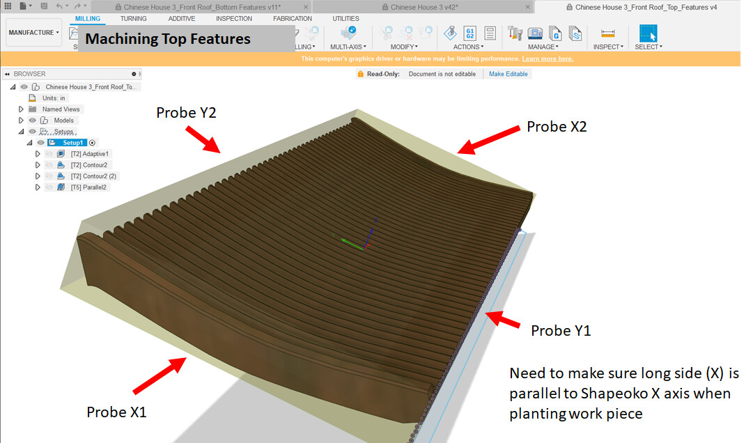
The second set of operations after making the flip needs to have the location pretty precise. I use this method for making sure my piece long axis is parallel to the machine X axis:
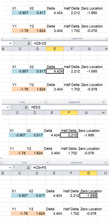
After that, I probe the piece as follows and use a spreadsheet to help me locate my reference zero. For instance, I sweep the left edge from the left until I contact the workpiece, and then enter the X1 location into my spreadsheet. I then sweep the right edge from the right side and enter that as X2. Then the spreadsheet tells me which X to move to so I can set my zero there.