Hello esteemed forum members,
I am new to CNC so please excuse the beginner questions, and thank you for your patience
I (believe I) successfully assembled and squared my Shapeoko 3XL, used Fusion 360 to model a wasteboard, and successfully created it from MDF.
It has 13x7 matrix of M6 inserts (from the bottom) and a few wood screws that hold it firmly to the original MDF wasteboard. The latter holes are slightly off-line with the former, due to boring them from the opposite side, and forgetting to compensate for the Y delta… lesson learned, no harm done.
I am now attempting to surface the wasteboard and make it 100% aligned with the spindle.
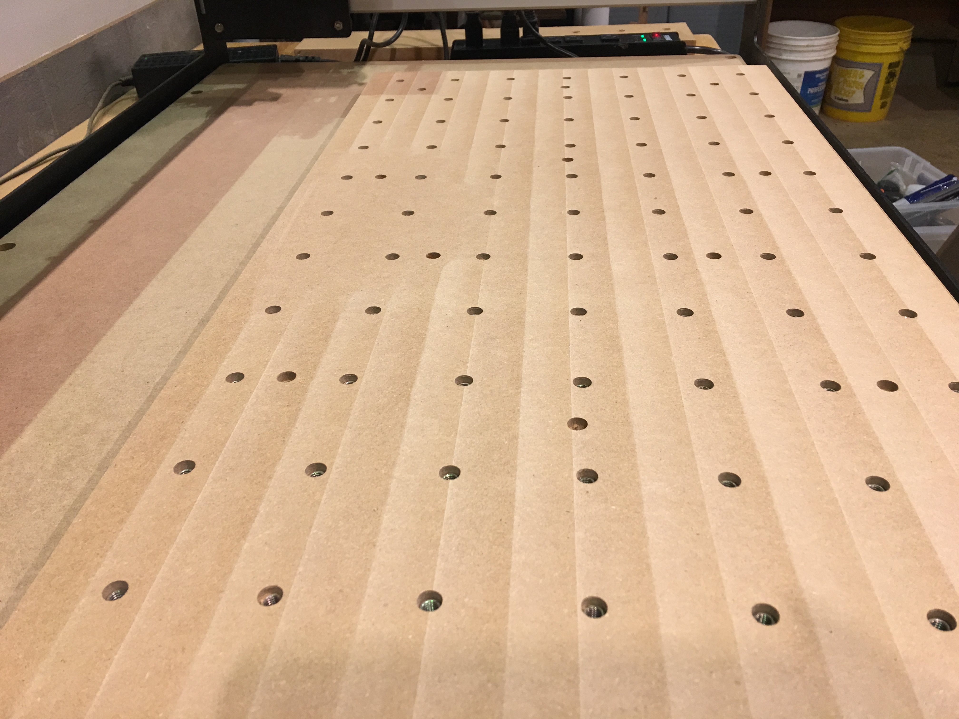
Attached is a photo of my wasteboard surface after a single surfacing run.
I can already see that will need a second run, as the back center was not surfaced (left center in photo) which means it is slightly lower on Z. I understand that’s OK and expected, and the reason for surfacing.
Before I run another surfacing job, my question is whether or not the visible path of the surfacing bit is normal, and what it means.
I’m using a Whiteside “1” straight cut CNC Spoilerboard surfacing Carbide Tipped" bit.
It seems that the ‘border’ between the surfacing paths is not consistent.
At some points the border can be ‘felt’ by sliding a fingernail across it, and at other spots it is hardly noticeable even visually.
If it is due to the spindle angle not being perpendicular to the board, how would I adjust it, when the angle seems to be inconsistent across various places on the board?
A suggestion for C3D I would like to see is a video tutorial on squaring and tramming the machine. I think a lot of new users (or total amateurs like me) need to see each step done in sequence to get real results.
I have already tried the method that Winston suggested, and even designed a small 3D printed squaring gauge for it.
You can download it here: https://www.tinkercad.com/things/lPuSi6c7FMI-spindle-gauge
Perhaps the arm is too short, but when using this it seemed like the spindle was square, which obviously was false…
I will use a longer arm, and try the 1-2-3 block method as well and report back with my results.
In addition to squaring up the spindle you might do a double-triple check of your V wheel/eccentric nuts. Quick way to check is to power up the machine, jog to center, grab hold of the router (which should not be running) and give it a firm shake. If you feel any movement, find where it’s moving and adjust. No point in tramming or leveling if the wheels aren’t engaged, like trying to shoot a gun with a loose scope. This check should only take about 30 seconds if everything checks out and well worth checking before delving into the rest of the mess.