I have not tried that yet. yes i have checked for play, im using the 1/8 pin that came with the Bitzero.
The 1/8" pin that came with it.
1 Like
After numerous lost parts and failed attempts at diagnosis, and now several days of investigation, we’ve been able to prove that our bit setter is offset by approximately 0.015” in the X and Y axes.
Because many of our parts were cut and then flipped, the problem was compounded, resulting in parts with errors up to 0.03” that we couldn’t resolve!
Anyway - is there a method to apply an offset to the bit zero in firmware? Or, do you have an alternate solution?
Whats odd is that it is consistently off.
Hole sizes, internal dimensions not related to a sidewall etc are all within +/-0.003” which is great, so we think the machine is good, just the bitzero is a problem.
Have you tried another pin to see if that is possibly the cause?
I don’t believe that CM exposes the offsets or dimensions the algorithm uses versus the puck itself. I don’t know if any of the new macro-like functions offer any access to the puck coordinates such that you could build your own probe algorithm? Wanting such freedoms, not probing per-se but macros with system access in general, I swapped to gSender and am pleased with the move. Not right for everyone, but it suites me
I stopped using my bit zero for similar reasons. If I remember correctly, fusion 360 has a way to add an offset for zero.
Please let us know about this discrepancy at support@carbide3d.com and we’ll look into it w/ you.
2 Likes
I have sent an email. I have a call scheduled today with one of your tech team!!
1 Like
Do you happen to remember how to do the offset for zero in fusion360?
I did make my own zero tool and ran a test and it came out perfect. No offset. Confirming it is the bitzero v2 After the meeting with tech ill write on here any solutions if any!
I have sent an email. I have a call scheduled today with one of your tech team!!
Yes i have. I made my own zero zig to confirm and when i used that it came out perfect.
There is no way to apply an offset in firmware. I’ve got 2 suggestions:
- This is something support would probably frown upon, but the best option if you insist on using the BitZero. Just barely loosen the screws holding the plastic bottom to the aluminum body, and shift the plastic bottom in the direction needed to compensate for the offset. I think you can get about 0.2mm of wiggle room each way. This should help reduce the error you’re seeing, but will take trial and error to get it super precise.
- If you are using stock that’s exactly the same, or of a uniform shape, you should just machine a shallow pocket in the MDF wasteboard to locate your stock. It can either be a snug fit, or you can push it towards one corner. This will be way faster than using a touch probe in the long run, and dead accurate/repeatable. You can fine-tune the zero position after the first run and things will be super consistent for every subsequent run. Using edges or stops to precisely position parts is how most people would setup stock in a production environment. Even on big machines, using a touch probe every single time will result in worse accuracy than a basic analog stop.
6 Likes
ok perfect thank you. I ended up making my own jig which has worked out pretty well but im going to definitely try what you said. Thank you again
Your guy Nicholas was awesome with our call. Thank you guys again for your level of communication!
Off the top of my head, I think you can make a sketch offset on anything you want then place a dot on that point in the sketch, move to cam and use that sketch point as your wcs. Just make the point the exact offsets it is in real life. Its a pretty shifty work around but it should work. (This is with fusion 360)
Would you mind sharing your procedure for finding X/Y/Z? I just did a post around this as I hadn’t seen this thread yet.
Thanks!
awsome yea i had looked into that was. over all i just made my own probing jig to cancel out all problems!
My new procedure? or the way i did it with the bitzero v2? bitzero v2 way was step by step from what the instructions said. probing off lower left corner.
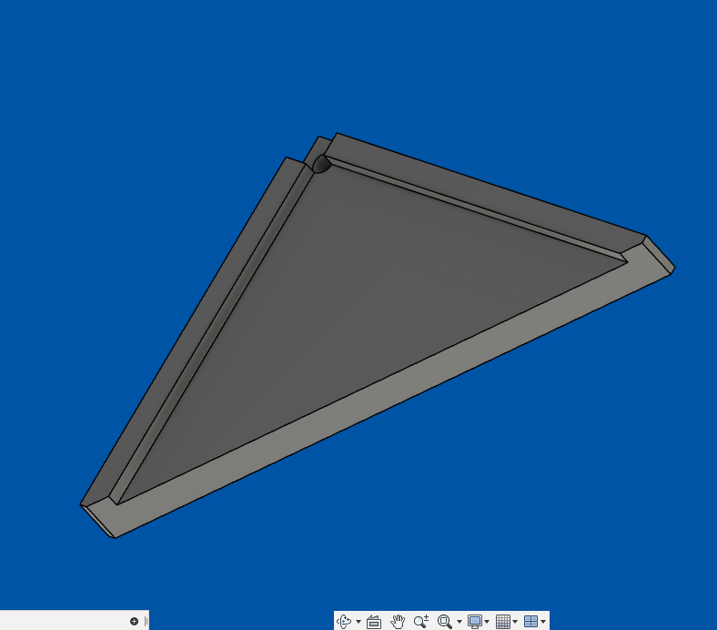
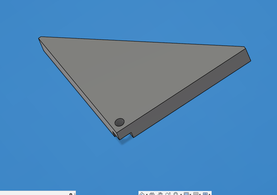
My new way i just cad up a corner piece with a 1/8th hole right in the corner and made edges on the bottom just like the bitzero v2 so i could square it up. Then i 3d printed the part. i can send you the file if needed. Pretty simple jig.
I was having weird bitzero issues last fall, the problem ended up being a loose drag chain (that wasn’t immediately obvious) that was causing a bit of resistance during the probe.
1 Like
This topic was automatically closed 30 days after the last reply. New replies are no longer allowed.