Brushless Makita Mod (unsupported)

Really nice to see some real world numbers Vince.

I noticed the Brushless seems to have a smoother feel too.

Still fighting chatter in Y+ with just semi aggressive adaptive (only toolpaths I’ve run so far). I guess my XL is just too wide to be pushed too hard? But then again, no real need for me to push, I’m in no hurry. Just my nature to test limits.

If these cheap PS’s can’t cut it we can always try the Meanwell’s.

1 Like

Assuming you’re measuring the input to the router, you’re using a 600A AC current probe to measure pulse width modulated (PWM) DC currents that likely won’t exceed 10A RMS. It won’t work.

All I know is that I was told to put it on the Amp setting and clamp around the positive input. Is there another way I should be doing this? The manual doesn’t cover much

Also what wont work? Sure looked like it was. It is a true RMS meter.

It’s a true RMS voltmeter, but AC ammeter.

You’re only measuring some of the AC content of the current. The duty cycle of the PWM waveform (whose switching frequency is likely above 20 kHz) increases with increasing router load. It should be pretty close to 100% (pure DC) at full load and your AC current probe would measure 0 A.

By the way,if you can measure the resistance of one or more of the router motor’s windings, that will tell you how much current can be drawn from whatever supply voltage you choose (I = V / A).

2 Likes

@Vince.Fab , I’m in agreement with @gmack. Not to distract you from your main interest in cutting aluminum, you’re in over your head when posting current measurements from a BLDC motor. Meaningful values can get complicated. No offense meant.

3 Likes

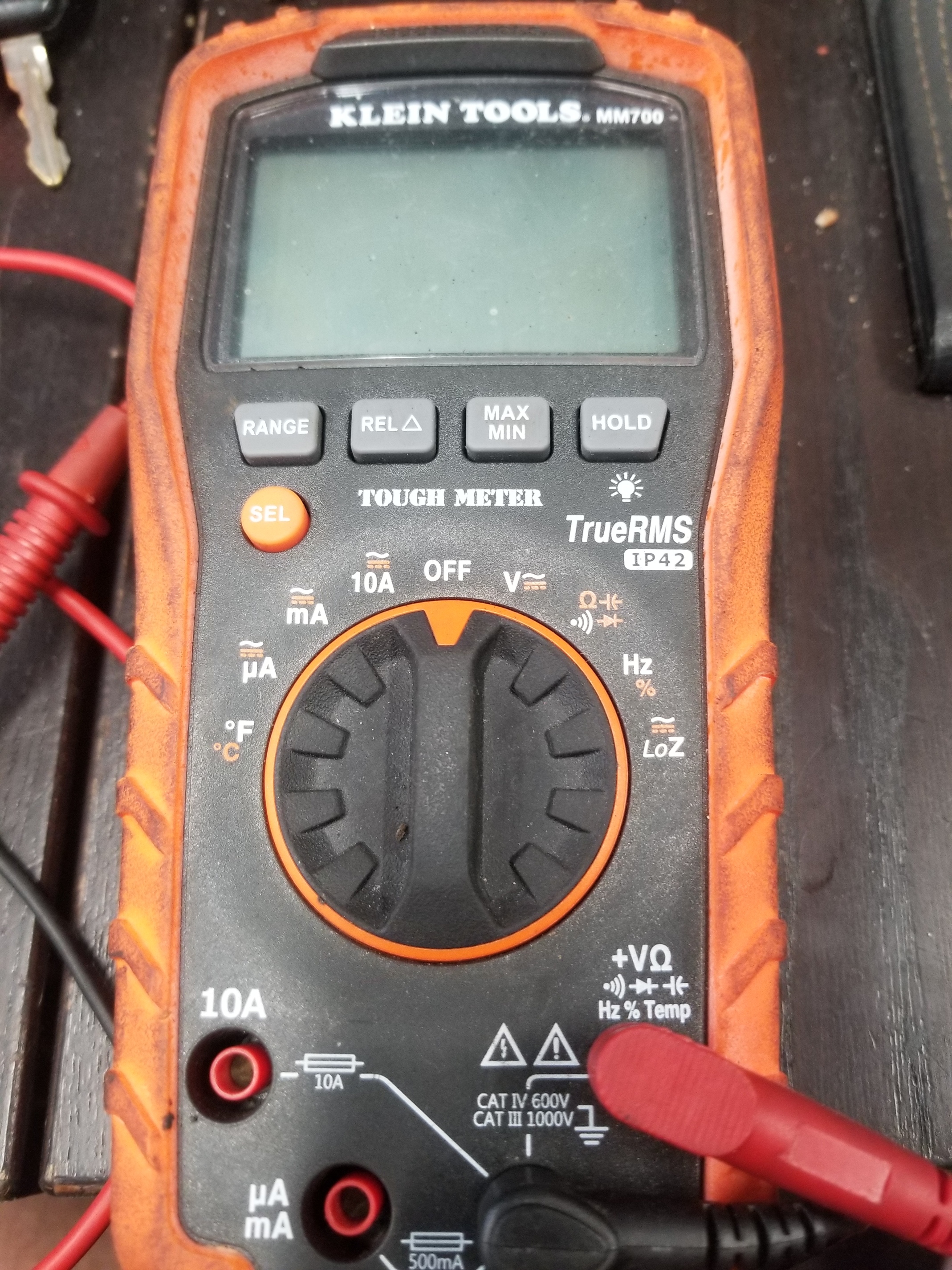
Electricity isn’t my thing so just tell me what to do lol. I also have this meter available. I know I’m in over my head. I can take the router back apart if needed.

Also my main interest is trying new ideas, pushing percieved boudaries. I really wanted to give some type of data that would tell us how much power this thing is consuming. Not just make it work after everyone said it wouldn’t.

1 Like

If your meter wasn’t limited to 400 Hz for RMS voltage measurement, and it could accurately measure the RMS value of low duty cycle high frequency PWM waveforms, you could use a current probe to convert the current to voltage. But, most DMMs only measure voltages accurately to 400 - 500 Hz, so you’d need to use an oscilloscope with a current probe. If you’re willing to spend over $3000, you can get a really nice scope that make those types of measurements easy.

There are less expensive options that require considerably more effort.

IMO what you’re doing is really worthwhile, even without the power measurements. Cutting power is the product of material removal rate (cuin/min) and the unit power of the material being cut (HP/cuin/min). For 6061 T6 aluminum, that appears to be about 0.2 HP/cuin/min.

You can also get a measure of cutting power by using the battery with the router and measure how long it takes to discharge under various cutting conditions vs. when its not cutting.

2 Likes

@gmack and @CrookedWoodTex, thanks for chiming in. So we need a friend with an O scope? Anything else?

1 Like

As I added to my previous post, it would be a lot easier to just see how long it takes to discharge the batteries under various conditions. If the battery specs are correct, discharging it over a 5 hours or longer could be quite accurate.

You can measure the power supply’s consumption. Switching supplies are very efficient and what is being consumed should approximate what is being produced.

Switching supplies also use high frequency PWM - so that won’t help.

Seems simple enough. You have a Makita battery Vince?

I have a 6s, 5000 maH but no comparative baseline

Output is high frequency, input is still 50-60hz mains. Assuming is a cheap supply, something like 75% efficient, multiply by 1.25. If you have an efficiency rating for the supply, use that. Don’t worry about the output.

Output voltage is DC (via output filter), input current is high frequency PWM to enable the use of smaller transformers.

No. Input to the power supply. It’s plugged into the wall. It’s 50-60hz 110-120v. Measure power into the power supply, not the output to the router.

I stand corrected, “The current drawn from the mains supply by this rectifier circuit occurs in short pulses around the AC voltage peaks. These pulses have significant high frequency energy which reduces the power factor”. So, RMS current measurements likely aren’t much/any easier on the input than on the output.

That hasn’t been my experience testing the draw of digital supplies connected 120V AC. What my clamp-on meters show, has closely approximated the manufacturer’s specification for the device I’m testing.

But there is really little point in discussing, when stripping some insulation of a cord is all that is required to find out.

2 Likes

Your 22V 5 Ahr LiPo battery should be ok if it doesn’t break the drive electronics. If it’s open circuit freshly charged voltage is much higher than that you might want to discharge it a little to reduce the voltage. You could also pick up 3 cheap 6 Volt lead acid batteries and connect them in series.

Battery discharge tests with a variety of power resistor values would allow you to “calibrate” the battery energy capacity (Ahr) for differing power draws.

2 Likes

Huh - I don’t understand!

[quote=“cgallery, post:102, topic:10658, full:true”]
That hasn’t been my experience testing the draw of digital supplies connected 120V AC. What my clamp-on meters show, has closely approximated the manufacturer’s specification for the device I’m testing.

But there is really little point in discussing, when stripping some insulation of a cord is all that is required to find out. [/quote]

The clamp-on meters need to clamp to hot or neutral, one or the other, not both. This typically requires removing some outer insulation on a three-conductor (hot, neutral, ground) cord.