Sure but you should be about to run the motor wizard and choose small inrunner. Lemme know if that doesn’t work
1 Like
Oh I am an idiot. LOL
1 Like
Hmmm. So still having an issue. I have to manually turn the shaft to get get it to start spinning. Once I do it is happy.
1 Like
Are in the Experiments tab? Try a duty sweep starting at 0.05 to 0.50, step 0.02, ts 0.50
I think it has to do with running sensorless. My hub motor was a little bit of a pain. I think with proper control it might act different.
1 Like
In General -> Advanced I had to set the Minimum Duty Cycle to 3%.
1 Like
Or not… Still sometimes have to do that.
1 Like
Yeah still spotty with me. I’m just pushing buttons now. How’s the hall setup?
1 Like
Looks like I can run only one test. Once I do I have to power off the VESC, wait five seconds, then power it back on. Then I can run another test just fine. If however I spin the shaft it spins right up. Thinking maybe a bug in the tool.
The hall sensors are reading just fine.
2 Likes
I was able to change it over to BLDC mode, run a detection and connect a wireless controller to it to power through the rpm range. Still needs some tweaking but its fun.
2 Likes
I am still having issues getting the dumb thing to start after one test.
1 Like
I’m not sure if those tests are the greatest for operation. Mine would occasionally stumble during starts and run rough in the rpm test but with the controller its smooth, responsive.
I’m thinking about bench testing the carbide3d controller pwm output and just using UGS to connect and unlock so I don’t have to home.
1 Like
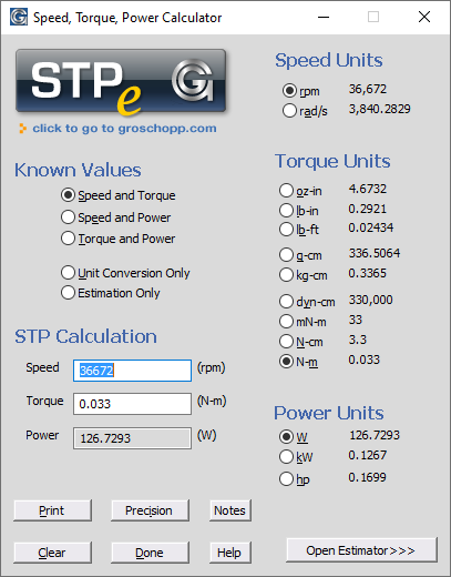
@Vince.Fab I think I’m starting to understand - please (anyone) correct me if I’m wrong. With your 27.2V power supply providing 27.2 * 0.949 = 25.8V to the motor, its no load speed is 73345 / 2 = 36672 RPM and it’s current is 4.95A. So the motor’s Kv is 36672 / 25.8 = 1421 RPM/V. The torque constant at that speed and load is 30 / 1421 / 3.1416 = 0.0067Nm/A. So, the motor torque is 4.95 * 0.0067 = 0.033Nm and its output power is 127W.
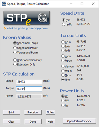
The VESC thinks the motor can handle 51.32A. 51.32 * 0.0067 = 0.344Nm, so folks in that hobbyist world would likely call it a 1321W motor. Maybe ~200W continuous maximum (200 - 127 = 73W for the fan and cutting at that speed?)
1 Like
Ahh, but you’d be giving up the motor current monitor, which could be used to quite directly and accurately provide cutting torque and force!
I removed my fan and plan to watercool. I just wanna feed it more power than the stock controller and control it automatically. Keep it simple.
How else would I control it?
You need good thermal conductivity from the motor windings to the housing to get the heat out through the housing. If that exists, something as simple as using thermally conductive epoxy to glue copper tubing containing cold water wrapped around it should help.
I’m not a software guy, maybe @LiamN or somebody else has some ideas on how to control and monitor it without the VESC software. Maybe they could even do the simple calculations necessary to enable a “real time” display of cutting forces in Carbide Motion. That would be the ultimate “Load Meter” for a CNC router! It would also make it easy for users to help develop more accurate K-Factors for speeds and feeds calculators.
1 Like
I really do not know how you would water cool this thing. The motor is separated from the metal housing by plastic. Running it without air going through that housing and the plastic could deform.
I was hoping to control this thing directly from the Carbide control board, but I am still waiting for my Shapeoko to ship. I have also thought about replacing the control board with something like a Duet board. I have tried controlling it with a PWM output from an arduino, but that is not working.
VESC supports control over a UART interface so another option might be to build a conversion module from an arduino. The Carbide board sends a PWM signal to the arduino and the arduino converts that to UART commands for the VESC. This also allows for a lot more feed back from the VESC. For instance if the VESC goes into a fault state the arduino could raise have an error pin that triggers an E-Stop. That way if the VESC decides to stop the motor for some reason the Shapeoko stops too.
3 Likes
In other news it looks like the motor temp input on the VESC is just a 10k NTC thermistor tied to ground. Should be super simple to add that so we can better monitor the motor temp. Monitoring that should allow @Vince.Fab to squeeze every last bit of performance out of this thing.
2 Likes
I’m a dummy. We can just use a basic RC circuit to convert the PWM to an analog voltage and use the ADC input on the VESC.
3 Likes
It sounds like monitoring and displaying motor winding temperature (with thermistor, thermocouple, or IC) would also be prudent to “milk this thing for all it’s worth”. But, since motor losses increase with the square of speed and cutting induced losses increase proportionately with speed, lowering the speed might also be wise.
I personally do not plan on running it past the 30k RPM Makita designed it for, though I would like to get more torque out of it. At lower RPMs (sub 10k) it might not be a bad idea to have an auxiliary fan pulling air through it as the built in fan will be running slower than Makita intended.
1 Like