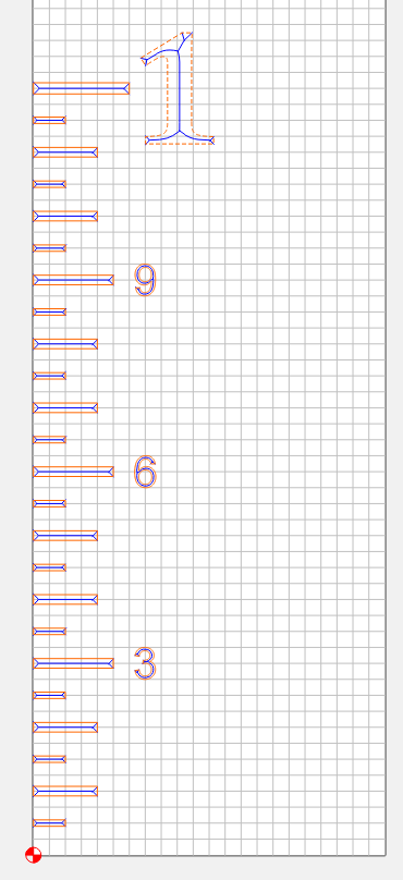
Here is a simple vcarve for a ruler using CC 414. You will see all elements are set in the v toolpath apparently correctly. However the simulation shows the 4.5" and 10.5" marks as two dots and the 6.5" and 10.5" marks are missing entirely.
I have deleted the 4 bad marks from the Design and copied good ones in their place - but the simulation still shows it incorrectly.
I did a test cut and all is fine - v-carves were as the Design not as the Simulation - so it’s the simulation that is incorrect. Looks like a bug to me.! I have uploaded the c2d file
broken_vcarves.c2d (219.0 KB)