The process is very simple. Let me start by saying that these are my personal findings and that I have only used them on my machine. I don’t know if Carbide 3D supports this procedure as you are changing the WCS (Work Coordinate System) that your machine uses to know where it’s at. These values will be stored in EEPROM and will be the default every time you start your machine.
Since I use the center position of my milling table and the Y-axis as my axis to flip, I needed to be as precise as possible with this coordinate. Also, this procedure works for me because I have the sea of holes milling table.
Here we go:
I discovered this in McMaster Carr:
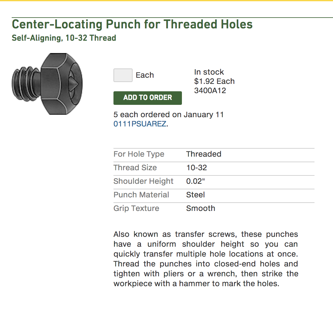
-I placed it in the center 10-32 threaded hole of my table and used the thinnest, most pointed endmill I have which is my engraving endmill.
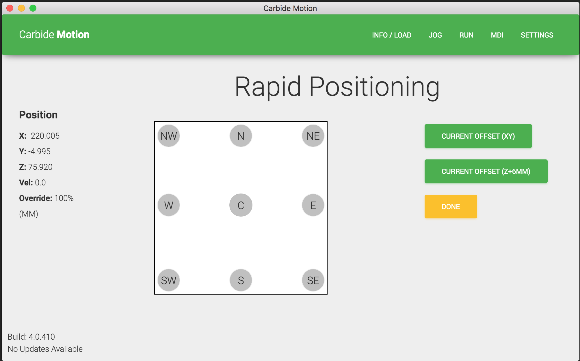
-Use Carbide Motion to move your bit to the center position with the rapid positioning screen. If everything looks aligned, you have nothing to do. If not, continue along. I used a microscope USB camera I had bought on Amazon a while back to be as precise as possible.
-Clear all offsets
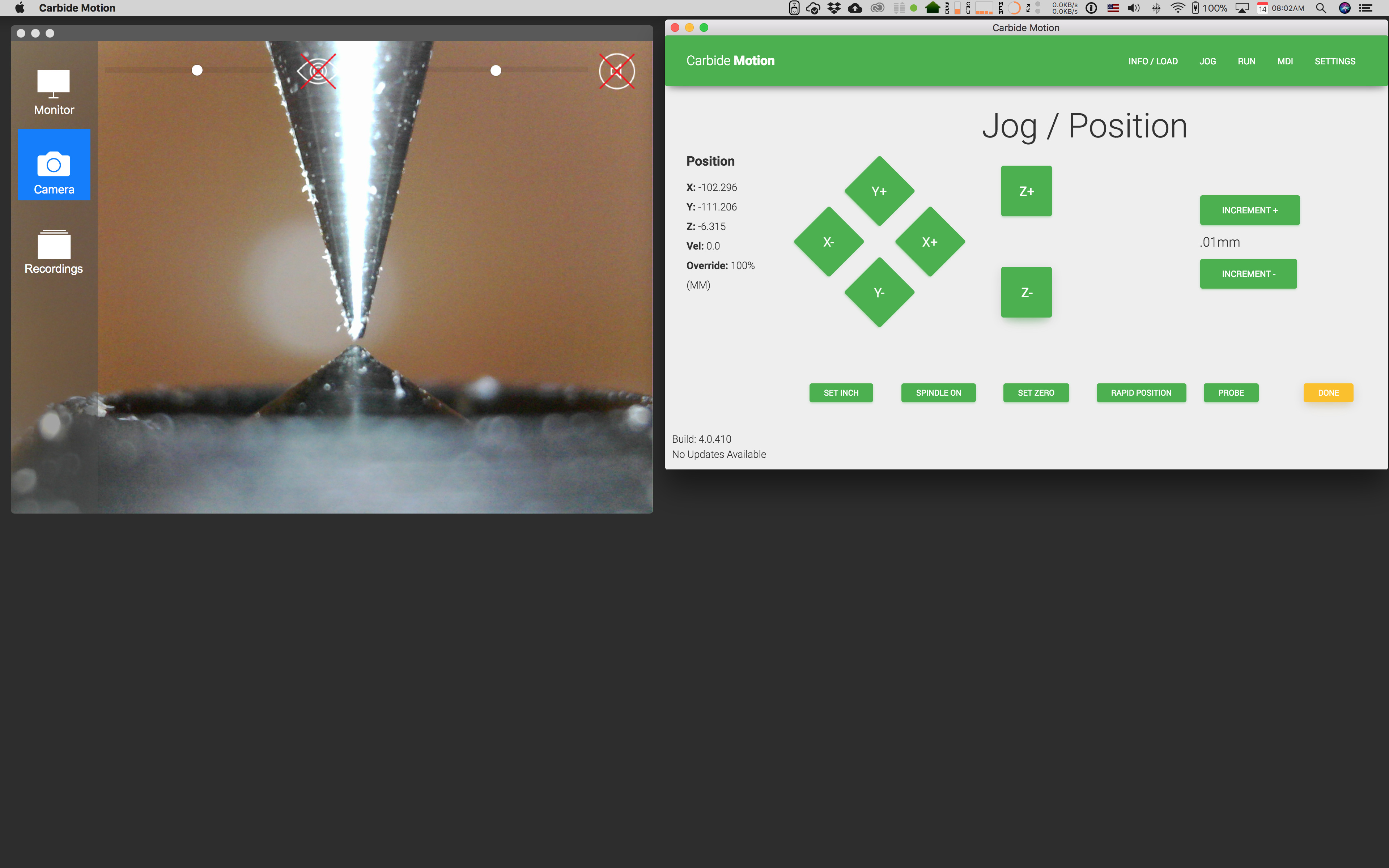
-Move the tip of your endmill to be as close as possible to the tip of the center locating punch.
-Note the numbers for your X and Y position. These are the center of your table in the WSC.

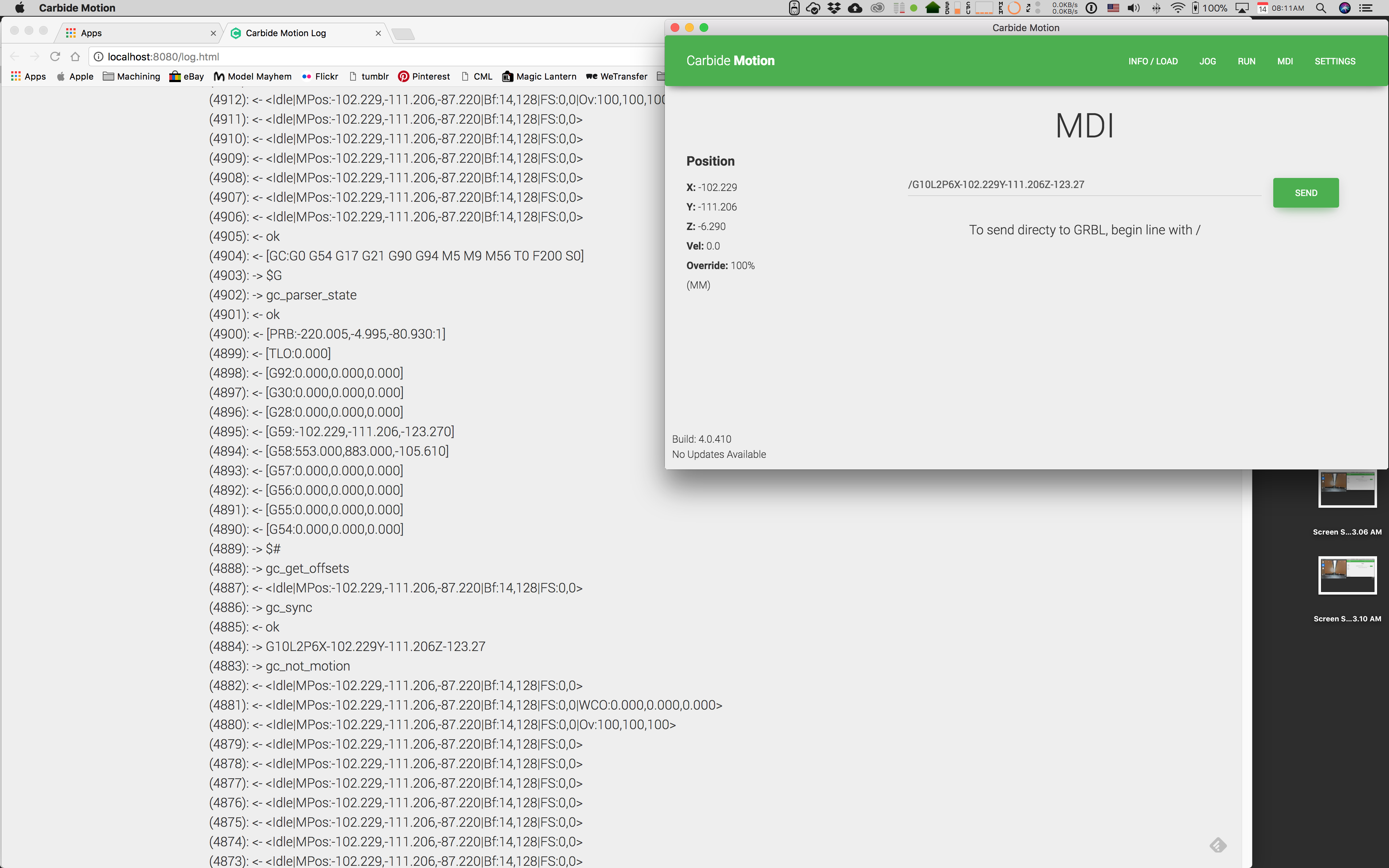
-Go to Settings and click on Open Log
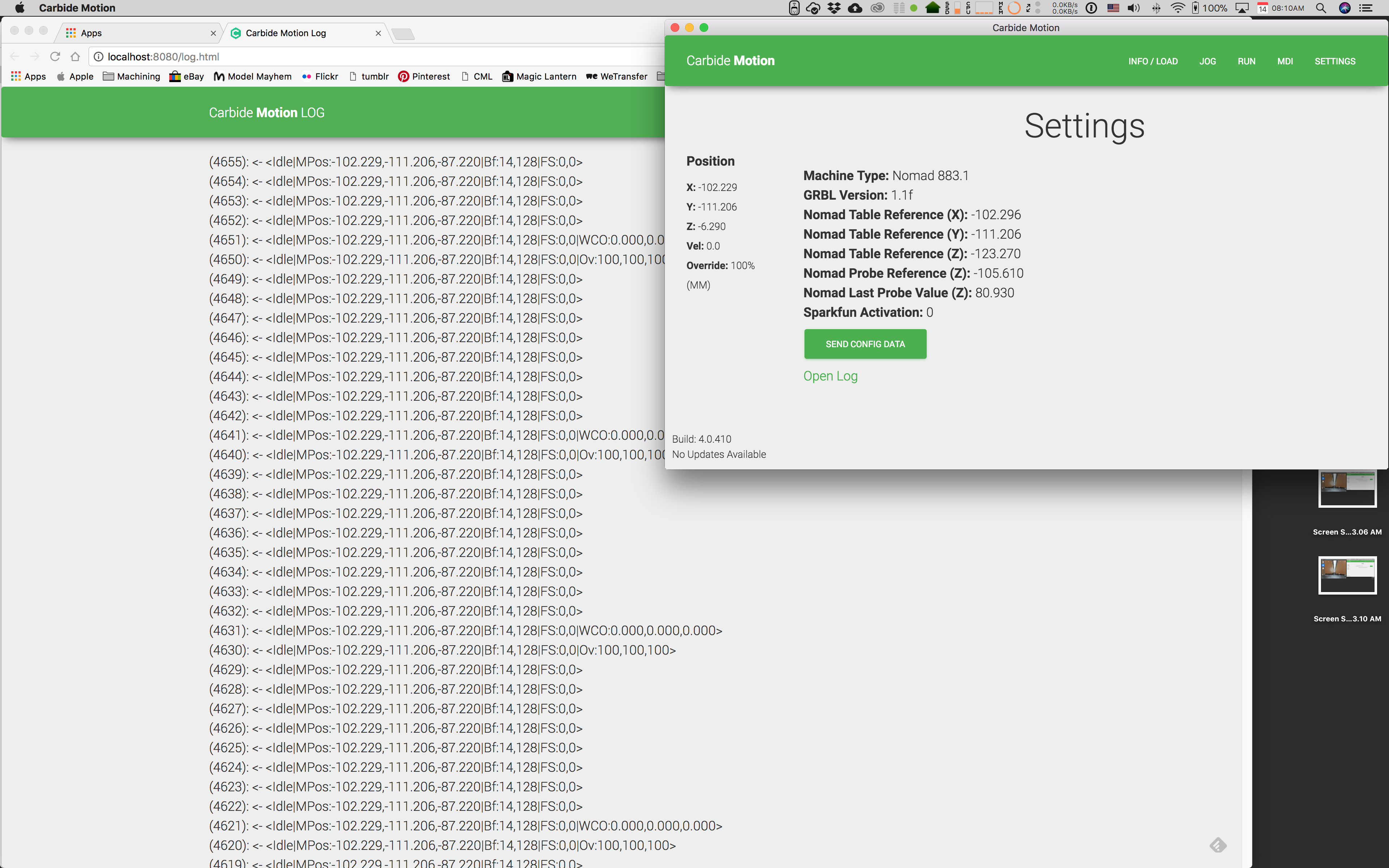
-Click on MDI and send this code:
/G10L2P6X-102.296Y-111.206Z-123.27
-It is very important that you replace the X and Y values with the numbers you wrote down from your machine.
-Click on the JOG button to re-home and check that everything is ok.
Finding the center-locating punch for threaded holes and using a USB microscope camera helped immensely to be as precise as possible. If anyone has any comments or revisions to what I describe, please let me know. Hope it helps someone.
PS: this is the USB camera I have: