Carbide 3D belt tension accessory

I’m targeting roughly 56Hz with a 20in span

Not to hijack, just a quick aside, as I am a new owner & getting near to building my PXL, can someone link me to an explanation of belt “hz” or explain it & how to measure it? Thanks! I am going to read the link above, maybe it covers “hz” aspect. In case it doesn’t, can someone explain about hz?
Edit: I see, measuring tone. I saw a guy who makes crazy cncs on youtube using a guitar tuner app on his belts.

I believe this was discussed in:

2 Likes

Check out the post Will linked, if you’ve got any more questions then ask away.

1 Like

Just wanted to update that I bought two M5 x 16mm (the stock Shapeoko Pro comes with 12mm) and found it way easier to evenly tension my y belts. Not tensioning too high of course, just enough :wink: I just found it hard to get the thread started with the shorter screws

2 Likes

The Pro is different than the SO3 in that there’s about an inch of space between the front/rear plates and any pulleys. That gives some room.
What about a simple clamp like this?
image
image
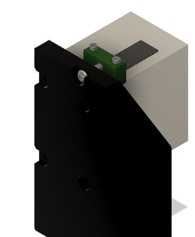
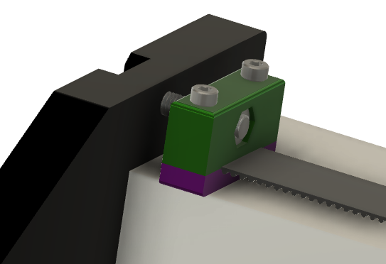
You’d have to trim your belt more, but you could get almost 15mm of tensioning.
I’ll upload STLs if anyone wants 'em.

9 Likes

Here are the STLs if someone wants to try these out.
ClipBTM.stl (462.5 KB)
ClipTOP.stl (149.6 KB)
I’d print the big part with the M5 nut space facing up (no supports).
The bottom, I’d probably print with the M3 nut space down, but with light support there.

6 Likes

I personally found that using a screw just 4mm longer solved my problems. I used gates app and measured frequency. Before I just found it hard to get adequate tension on one side, so a slightly longer screw made that much easier.

3 Likes

I found it interesting that the holes for the screws themselves were tear shaped, not round. I had assumed they were meant to be positioned with that pointed up?

Yup… For the top part. I just carried the shape through to the bottom section. Really helps with printing through holes like that.
Let me know if you print them.

1 Like

The thing about the current belt loop design is that they work the best when they’re fully tightened against the plate. That doesn’t leave any room for adjustment. Whether you feel you need to adjust belts or not is probably dependent on the individual.

1 Like

I’m re printing the bottoms the way you recommen. I printed them as I had assumed, and split one puttng a nut in. They would have printed cleaner if the nut pocket were turned thirty degrees to have the points up. Another change I would do, would be to recess the m3 nuts further up into the bottom clip, an 18mm screw just cleared the nuts, but being cheap, I stripped one out. ended up using 20mm screw. And I’m not to wild about the screws extending past the bottom of the clips.

1 Like

I could probably thicken the bottom without causing too much lift on the belt. I always have it in my mind that M3 threaded inserts would be better than the tiny nuts, but I have a problem with tracking down the tiny inserts when it comes to modeling these things. I generally try to keep things as simple to print as possible.
You definitely want to print the bottoms with the belt teeth up for maximum strength. You wouldn’t want to have it pull apart when tensioning. I’d also recommend PET (or stronger) for this.

1 Like

I pretty much do all of my printing with PetG.
I just tried installing these, and an M3 x 18mm button head screw would be the maximum length of screw to use. I had to revert back to the clips, as the longest M5 screw I have was 20mm, and I would want a minimum of 25 for adjustment.
All in all, It looks like it will work. I think to much time was spent looking for a solution at the front of the machine, and you solved it at the back.

I received my M5 screws today, and installed your tensioning blocks. Did you intend to have the hole for the M5 to be offset? about .15mm?

No. Which way?
I haven’t had a chance to print yet, so everything is based on measurements and guesses.
Got a pic?

Check out the layer lines.

I had to flip it over for the hole to line up with the machine, but other then that, it works, and easy to adjust the tension equally.

Oh, the hole was not centered vertically on the part. Off the top of my head, I measured from the rail to the hole to be 11.5mm. The height of the block was probably based on standard M3 screw lengths…18mm, I think.


After the post I checked it out. I don’t care. It works.

Thank You for the clamp

The pics look right. The top should be the shorter side… Is that how it fits?
I did notice the slightly rotated hex nut after I uploaded the STL, but that wouldn’t affect anything other than OCD.