I’m keen to get a proper diagram for this version. I have the older 2.1 version that floats around but it’s missing the important Nomad Connector. The reasoning behind this is that I want to tap into some pins - but I’d have to manually add them - something I’d rather not do if I can help it.
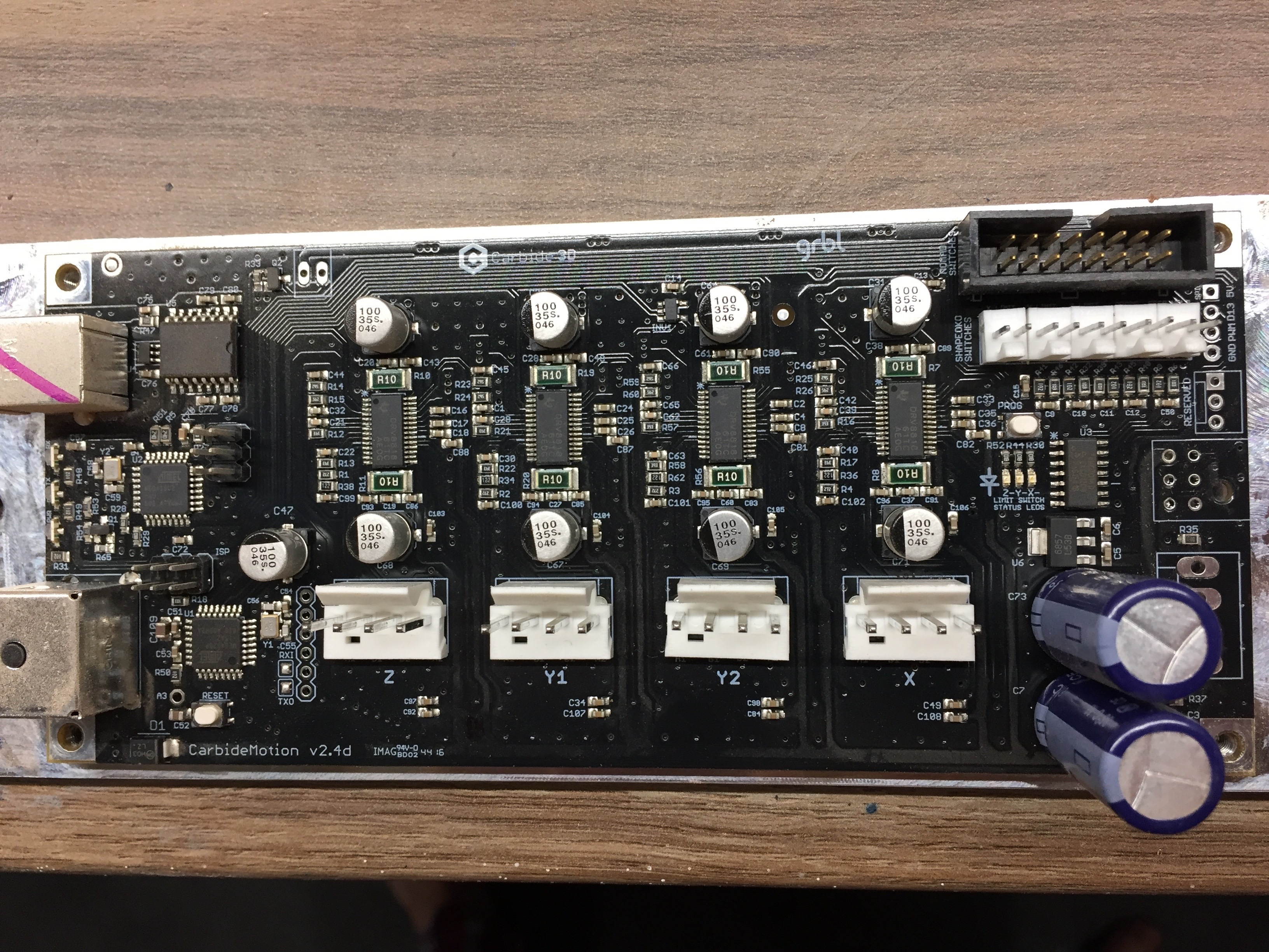
On the top RHS there is a 5V and ground output and PWM (I believe for Laser control) There is also something called D13 - spindle enable.
Now just below these 4 pins there is also the set of 6 pins and then 2 sets of two or 4 pins which are likely in the same configuration as the earlier board:
However and my main point - at the top right of the board there is what I believe to be the Nomad controller plug (big black one) - I would put a couple of quid on all these pins being in that connector - and if I could tap into a couple of them I can save a bunch of time soldiering on pins - it would also allow me and others to quickly attach say a Laser accessory or Super PiD etc?
I am after this or something like it too-for my swapable board project . I am aiming to have everything run through one connector between a board and the ShapokoXXL. There are 47 pins (not counting the Nomad Connector and there are spots for more pins…) on the V2.4d board, 22 in use as per Shapeoko assembly instructions, and then the 5 visual conductors a piece for the USB and Power connectors… I want to make sure I have a path for every connection I could use for additonal upgrades-while some are labeled, some are not! I have a 2.4d board and a second board on order as of yesterday. Don’t want Carbide to make some great new add on available (Carbide Connect/Touch Probe/Laser head, etc,and t find out I need to open it up to add more connections!
Did anyone get to find out if the black connector is indeed the ‘Nomad Controller Plug’ - and - if some of the pins on same are for 5V & Ground Output?
(I’m adding a SuperPID and would like power for it to come from the Carbide Controller)
Sorry to revive this old thread, but I would really really like to know the pinout for this big black connector (I have rev 2.4d of the controller). I did send an email to support moments ago, but in case someone here has the answer readily available and could post it, I think it could benefit other users someday.
If someone could send me a clear picture of the back of the board, I might be able to work it out. Not sure what you’re looking for here, but it’s all homing switches, and I think a the door switch for euro models. If you’re looking for the secret “Haas tool changer interface”…it’s not here.
Nah it was a much smaller dream of having the “PWM” signal connected on one of these pins (in addition to it being available in a plated hole on the PCB itself, next to the connector). The reason being my lazyness to unmount the board to solder 2 wires to get access to the PWM signal, and hoping I could just plug a female connector there and be done.
But indeed this J2 connector has a clear “NOMAD SWITCHES” silkscreen marking, which I had not paid attention to before, and if you confirm it’s all homing switches, no luck then. Looks like a lot of pins for 4-5 limit switches though (I guess X/Y/Z/door/tool changer?)
I’ve never seen a full pinout of a 2.4e board, and I’ve been immensely annoyed by what seems like a common response of “It’s like the Sparkfun board”, which is Not Even Wrong. I can say, however, that at least in earlier version of the controller, the PWM signal was also available on a pin on one of the six-pin blocks on the left of the board. Going by a photo from an old post, PWM and ground were the right two pins on the top row of the block near the power receptacle labeled “ARDUINO_ISP”, but that wasn’t a 2.4e board.
I just got my machine honed in just perfectly, so I really don’t want to start taking things apart to hunt up the PWM signal, but it should theoretically not be too difficult to check for PWM signal if you’ve got easy access to your controller.
Ditto for the “just check the Sparkun schematics”…sigh
Thanks for the interesting lead, I’ll check that tonight. For sure I would never have looked for the PWM signal on something labelled “In System Programmer”…
I have version 2.4d, so we’ll see.
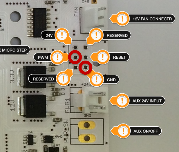
Allright, I plugged a set of wires on the two said pins, GND is the on in the top right corner, and PWM is the one left of that.
Using a voltmeter:
I initially read 0V
When I enter “M3S10000”, I get 4.96V
When I enter M5 (stop spindle), value drops to 0V
When I enter any other spindle speed value, say M3S5000, I read 4.96V
Used my pocket oscilloscope, the signal looks constant flat at 4.96V.
I expected a…PWM signal, not a constant 5V signal.
I checked the signal at the PWM plated hole on the PCB, same thing.
Is there a magic GRBL setting somewhere controlling whether PWM is a variable square signal or a plain on/off signal ?
What are your $30 (Max spindle speed) and $31 (Min spindle speed) values? I imagine your $31 == 0, but if your $30 is, say, 1000, anything above that clips and gives a full PWM duty cycle.
The labels on the pins down the right side of the board are kind of obvious - and the 6 pins in the middle right of the board are the connector that on a nomad goes to the spindle drive board. Both have PWM.
Yeah the connections on the right are indeed pretty obvious (or at least documented), what was less obvious is that PWM is also available on the 6-pin ICSP header on left side of the board, and it made a big difference for me as I was able to plug a female dupont cable onto these pins and get that signal with no soldering required, i.e. without the need to unmount the controller board.
By the way, just to document what has been said above for future readers, the ISP header (on v2.4d and probably all boards going back to the dark ages) has this pinout: