Carving out significant depth, having random problems

Hi all, I wasn’t sure how to categorize this or even what is going wrong, but I’m having some trouble with a bit that I am using. The cut goes just fine except with this bit, so I think I’ve at least narrowed it down to that. My current project (routing out letters from ~2" of wood) starts with a fairly deep rough cut - I’m using a 1/2" straight bit going to a depth of 1.4" for the rough pass (the cut length on the bit is 1.25") with the following parameters (currently using inches for measurement - yes I want to switch to mm, but that’s beyond me right this second!):
Stepover: .25
Depth per Pass: 0.080
Plunge: 35.0
Feed Rate: 75.0
RPM: 18000

When I first wanted to write this, I wanted to see if there was a way to speed up the cut. This project (routing out letters), is taking about 2 hours per, and I’m pretty sure that I can adjust for shorter times, especially on the other bit that I use, but now I’m wondering what I’m doing wrong. The second bit that I’m using, which handles more detail, cleanup, etc, is the Amana 3" compression bit (Model 46016-K), and that seems to be fine, I’m using the following parameters:
Stepover .125
Depth per pass: 0.040
Plunge: 12
Feed rate: 60
RPM: 18000

Whenever a problem happens, it seems to occur with just the 1/2" straight bit (I’m using a Freud). Here is a compilation of the issues:

  • The router stopped moving. It was still spinning, but it wasn’t moving on the axis at all, just spinning in the same spot. I had to turn the whole thing off and restart. When I restarted, it seemed to zero properly, (I have the Pro, so I’m using the built-in bitsetter and the bitzero), but then went way too deep on the cut, didn’t retract far enough, and ripped its way through the wood. That was sad. I’ve actually had this happen a few times, where it seems to zero properly, but then everything goes wonky and it cuts way too deep.
  • The cut was working fine until it was about 1.3" deep and then all of a sudden, it went off kilter about 3/8" and then tried to keep routing into the side of the wood. It was as if someone had jerked the router over and then let it keep going, but I hadn’t touched it. The only thing I noticed was that the sweepy boot had some buildup in the brush part, but I have no idea if that could cause the machine to essentially move to the side.

Anyway, this has been really frustrating, because the cuts take forever (2 hours on average), and I’m using birch and maple, so I really want to figure out what is happening. I’m hoping you all can help. Again, the problem seems to be with the straight bit, but I also know that I could shave off some time if I could tweak the numbers on the compression bit.

Soooo… TLDR:

  1. What’s wrong with my straight bit, it keeps having random problems?
  2. Can the compression bit feeds/speeds be tweaked a little to decrease my cut times?

Does your router have the torque to make the cuts you are asking using the 1/2" tool?

Please note that the compression tool needs to be used w/ a depth of cut which fully engages the uncut portion, and allows the downcut portion of the tool to come into play.

Hi Will,

I never even thought of the torque/ability of the router to do this… I’m using the Carbide Compact Router that is offered with the Pro purchase. Here’s my complete ignorance showing - I have no idea if it’s enough. I’ve been toying with getting the HDZ, but I didn’t even think that maybe I should get a new router/spindle as well. Do you think that’s what it could be?

For the Compression bit, I’m using the specs that were recommended with #324. It’s basically the same bit, with a longer flute, but maybe the upcut/downcut parts are longer as well. Would that be the B1 length that I need to think about? https://www.amanatool.com/46016-k-cnc-solid-carbide-spektratm-extreme-tool-life-coated-mortise-compression-spiral-1-4-dia-x-1-inch-x-1-4-shank.html

#46016-K

Specification|(D) Diameter|1/4|
| — | — |
|(B) Cutting Height|1|
|B1|3/16|
|(d) Shank|1/4|
|Overall Length (L)|3|
|Flutes|3|

Thanks!

There were a few threads here about how straight bits are just…not necessarily our friends on a desktop CNC. I’m sure @LiamN will voice this much better than I ever could, having used straight bit like this one.

There are two main likely reasons for this:

  • losing steps on the motor for that axis. This happens when the forces the tool/router has to fight to move through the material exceed that max torque/force that the stepper motor can deliver. So the motor “skips” steps, and since there is no way for the Shapeoko controller to know that this happened, it will continue to drive the motor normally as if nothing happened…resulting in the rest of the cut proceeding normally but…in a different location from where it should have been. This is remedied by using less aggressive feeds and speeds/depth of cut.
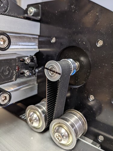
  • the stepper motor pulley slipping on the shaft, if the setscrews on the pulley are not tight or the pulley is not positioned correctly on the shaft (there must be one of the two set screws aligned to the flat on the motor shaft). Sometimes the setscrews are not quite tight enough, so the pulley does not slip under a low cutting load, but will slip under heavy load. The easiest way to check this is the marker trick: draw a line across the pulley and shaft. Next time the offset cut problem happens, check the marker line. If it’s not aligned anymore…the pulley has slipped at some point.
1 Like

Thank you! This is really helpful. I’ll slow my feed rate down - I don’t think I realized I had set it so much higher.

I also just realized that my compression bit has 3 flutes vs 2 … does that change the parameters that it can do? Can I increase the feed rate for it since it has more flutes?

I changed the settings for the straight bit to a feedrate of 60 and a depth per pass of 0.060. Hopefully that helps this issue.

One thing I am confused on are feedrate calculators. I downloaded G-Wizard, and I think it’s out of my depth (pun intended). But I don’t understand things like chipload and surface speed, and I don’t have the ability to discern what makes sense for my machine vs. a more heavy-duty one. Is there a super basic, non-engineer, non-physics, etc, explanation out there? I was a humanities major and my MA in religious history is not helping, lol.

Thanks again!

My attempt here

But it’s still somewhat the engineer in me describing things…so maybe not what you are looking for

1 Like

I’m in the middle of my first cut, and while a lot slower, it seems to be going well so far.

I realize I missed that part of the question, the answer is basically “yes”.

What matters is the “chipload”, i.e. the size of the bite that each flute takes into the material. The chipload depends on the feedrate, the RPM and the number of flutes like this:

chipload = feedrate / (RPM x number of flutes)

So for a cut that is working well for a 2 flute endmill, if you switch to a 3-flute endmill you can (and should increase) the feedrate by 3/2 to compensate, and end up with the same chipload. There are complications like the fact that chip evacuation on a 3-flute is not as good as on a 2-flute, but that’s another story.

1 Like

Could it be that the bit is rubbing due to the fact the depth your cutting to is 1.4 and your bits cut length is 1.25.?

No, the cutting part is wider than the shank and the stickout is enough that it doesn’t hit the nut. However, I do think that I was pushing it too much. So now I’ve slowed it down, and I’m not going as deep with that bit. I’m using a different bit to go deeper, and once I get to my next cut, I’ll be able to see if it works.

I decided to switch to a downcut bit instead of the compression bit. It really wasn’t cutting as cleanly as I would have liked, I had a lot of fuzzies on the top to clean up and even some on the inside. So I decided that maybe a downcut would work better, at least on the bottom part of the cut.

In theory you get the opposite result: a downcut will leave clean top edges, but have some possible tearout on the bottom edges, while an upcut will leave clean bottom edges and have some tearout on the top edges. A compression endmill is supposed to be the best of both world, but it works like that when one can cut deep enough that both it lower (upcut) and higher (downcut) section are engaged in the material at the same time. Which is often not possible for thick material, too much force on the tool.
What does work like a charm though, if doing an initial profile cut with an upcut or downcut endmill, a small depth per pass, leaving a little margin (“stock to leave”) compared to the intended final profile boundary. And then run a second profile cut, with a compression endmill, at full depth, that will remove the remaining material. As there is very little to remove then, it won’t put too much force on the tool, and it’s ok to run it at full depth.

1 Like

So here’s what’s interesting - that’s what I’ve been doing, taking out a larger chunk with the straight bit, and then doing a “finishing” pass as it were with the compression bit, but it did not come out nicely. I expect to have some cleanup, but I was surprised at how much was necessary during my last run through. I figured I’d try the downcut for this next one, and then see how it goes. I’m not sure I actually have an upcut bit… I’ll have to look.

I should add that I don’t know what depth to make the final profile cut in order to efficiently use the compression bit.

Okay, I did a little research (sorry for the multiple posts, this is generally my process, I ask a question and THEN try to find the answer)… it looks like I would have to make the cut 3/16" (.1875") in order to properly utilize the bit. I’m assuming then, the pass would have to be a lot slower if I was going to quadruple the depth pass. This is also a 3 flute bit, so I know, based on prior posts, that this may change the equation a bit. Am I off base in thinking that this may end up stressing the machine a lot if I try to go at the parameters I’m thinking of?

Full depth, or even slightly overcutting into the wasteboard. The idea is that the full length of the endmill goes and shaves off the remaining material off the vertical walls:

image

(illustration with an upcut endmill, but you get the point)

Now of course, this is so deep that this only works if:
a) enough material has been removed by the roughing pass that the finish pass only cuts that red part.
b) that the red part is really narrow, say 0.5mm / 0.02"

Let’s say you want to do an outside profile cut of a square that is 10" on each side.
You would first create extra geometry around that square, in the form of a slightly larger square, say 10.04" x 10.04"
You create a first regular toolpath with any endmill you like for roughing, and a small depth per pass as usual, and you cut that 10.04"x10.04" outside profile cut completely (possibly with tabs depending on workholding).
Then, you create a second toolpath, selecting the 10"x10" square this time, using the compression endmill, and program a single pass at full depth (depth per pass = total depth). That second toolpath will come and shave off the extra 0.02" on each side, leaving you with a 10"x10" square that should have a nice finish on all sides, because the compression endmill was fully engaged.

This approach is much easier when using double-sided tape or tape & glue as workholding, tabs are a complication.

Indeed you cannot just quadruple the depth per pass of the original, single profile cut approach, you cannot cut that deep AND wide. It’s either shallow and wide, or narrow and deep.

Hope I did not confuse you too much.
Maybe share your design file for easier illustration of how that could work ?

1 Like

HI Julien,

Sure enough, the pulley slipped today during my cut. It actually also started to pull out of the motor, so I ended up taking everything apart and retightening it all. Can I put loctite on the set screws to keep them in place? I’ve seen some posts about switching out those screws for more heavy duty ones, but that’s a solution that will require a purchase, and delivery time, and I’d like to get a solution together more quickly.

More importantly, in my opinion, is why it’s slipping. Could it be simply because they weren’t tightened enough, or do I need to adjust my parameters even further?

Thanks!

You can use loctite, but preferably the low strength one, the 222(purple in colour). Any stronger compound you run the risk of stripping setscrew or pulley threads.

1 Like

The key to securing the pulley is aligning one of the two set screws against the flat notch on the motor shaft. If you do that, use a drop of the appropriate Loctite like @BrokenEndmill said, and tighten them normally, it should be ok and not slip ever again, and you shouldn’t have to adjust cutting parameters (if the set screws are installed correctly, the motor will skip steps long before the pulley slips on the shaft)

2 Likes

Awesome, thank you so much for your help! I’ll try that and hopefully that will fix that.

I’m now stuck about halfway through my cut and I need to zero my stock to be able to start the cut again, and sure enough, I’m having issues with the zero. I use the BitZero, and it works (I’ve tried with multiple pieces) except for the piece that I need to use. I’m going to try to post a pic of my workpiece, but basically, is there a trick for zeroing using the BitZero on a piece that is thinner than the BitZero? It does the first plunge and gets the first point (I think) and then doesn’t move correctly and fails as it’s trying to move across for the second point. I literally tried 3 other pieces in different spots and it worked. Do I need to do a manual zero?