Nice take on traditional methods. I have used printers quoins on the milling machine and shaper when a vise is inappropriate, and wood wedges with 2X lumber for panel glueups (the 2X acts as a caul, and a pin or nail at each side provides bearing for wedges). Never had the need for elastic, but cutting metal on a larger machine, self lock taper run tight will gain nothing from the extra little bit. Wood can’t be wedged so tight without damage, and needs less holding force. I like this solution.
Great idea, thank you!
The printers quoins look like a pretty cool idea too…kind of spendy though. Makes sense that these exist for typesetting, just never really thought about it.
not very spendy from yard sales and fleas. one or two dollars a pair for 4" Challenge. Maybe $4 a pair on the auction site. They are a bit oversize for use with the Nomad, but there might be utility with the shapoko, as long as they aren’t hit with a cutter.
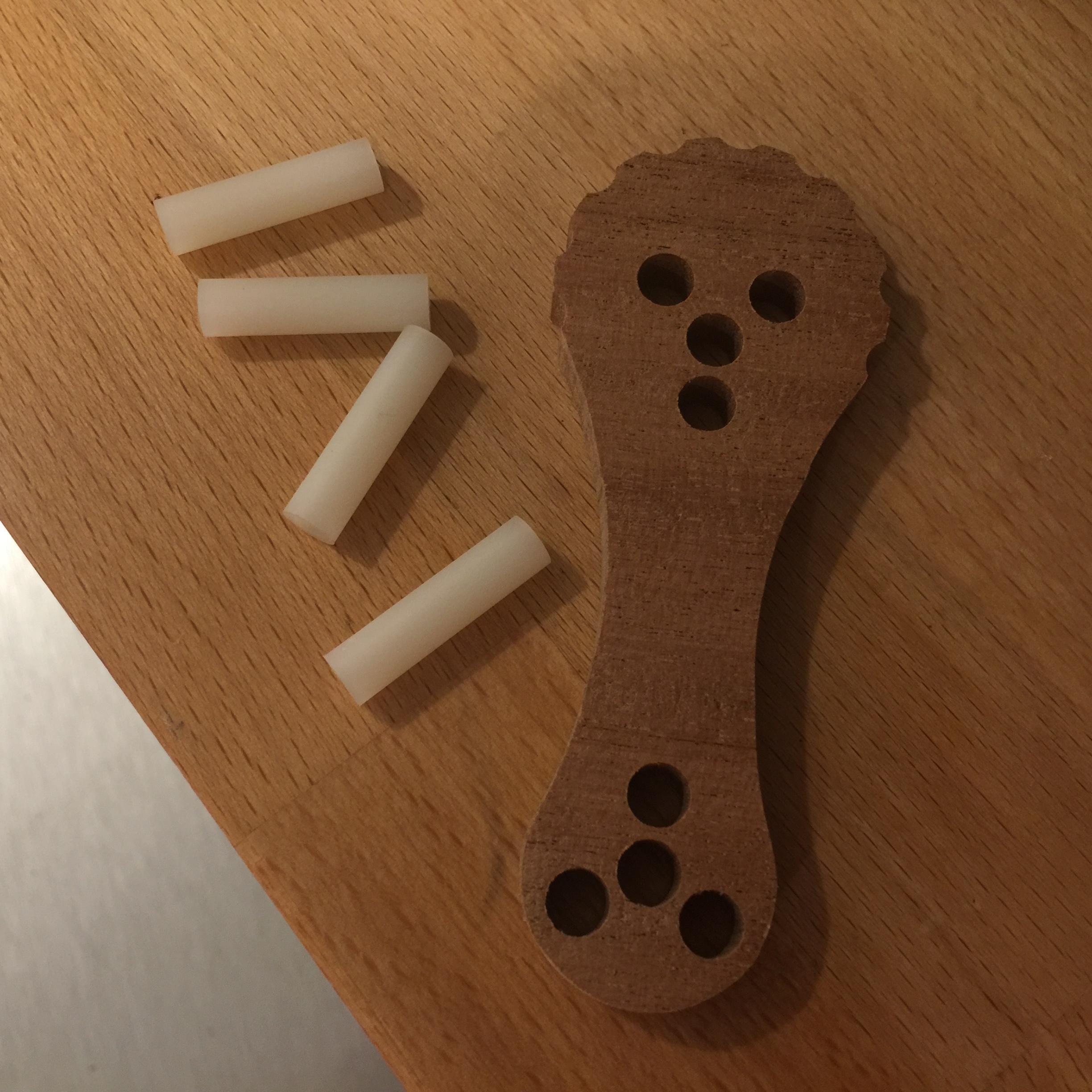
These clamps look very promising. I’ll build a scaled version of these for my Nomad today. Will post results later. If pressure is enough to keep the part in place, this seems like a very simple and elegant solution.
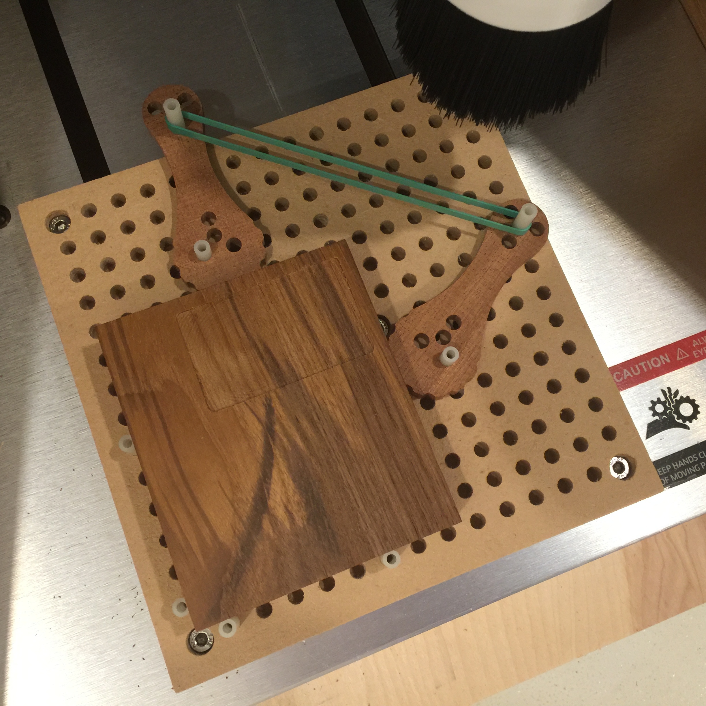
I can now say I’ve tried this and it works well. I’ll test it more in the next weeks but so far it’s working great. 1/4" holes on a spoil board, 1/4" plastic spacers, rubber bands and the eccentric clamps that I scaled down to fit my Nomad. I have to say that it’s extremely rewarding to be able to just make stuff like this. I’m making wedges soon too.
7 Likes
For anyone wondering about the rubber matting, it is the carpet mat, here is a link to various sizes on amazon. This stuff works super well, haven’t used it in CNC applications yet, but I use it all the time when I need to protect a very nice piece from being marred/scratched while working.
patofoto, any chance you could post the stl file for these cams? Thanks in advance!
CAD files would be great too…
Eccentric Cam.stl (154.6 KB)
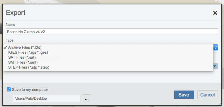
Here is the STL file. How should I export the CAD file?. I use Fusion 360 and here are the options I have:
I thought Fusion 360 had a mechanism for sharing designs built in?
Yes. You can right-click on a file icon in Fusion 360, and click Share -> Share Public Link….
1 Like
Yes I can share that way but it needs to be via email and every access needs to be created individually.
Or you can send it directly to grabcad (publish to grabcad in the file menu) from fusion (which has all sorts of nifty stuff). You can share all of them at once. It’s sort of a github…for cad. I publish to here from time to time (example: https://grabcad.com/library/fixturing-clamp-1 or https://grabcad.com/library/let-stuff-go-sign-1)
The STEP file is usable by pretty much anyone I think, the f3d archive is most useful to fusion users (like me…)
There’s an option to share a URL to the model. You don’t need to e-mail it, although that is an option if you try to share from your Hub account.
For example, this is a joystick that I modeled for an arcade cabinet project. In Fusion, just right-click the file, click Share public link and enable “Share the latest version” and “Allow item to be downloaded”. You’ll get a short-URL like this that you can copy to a forum post…
Thanks for that tip. Have shared before but only via making groups. Here is the link.
2 Likes
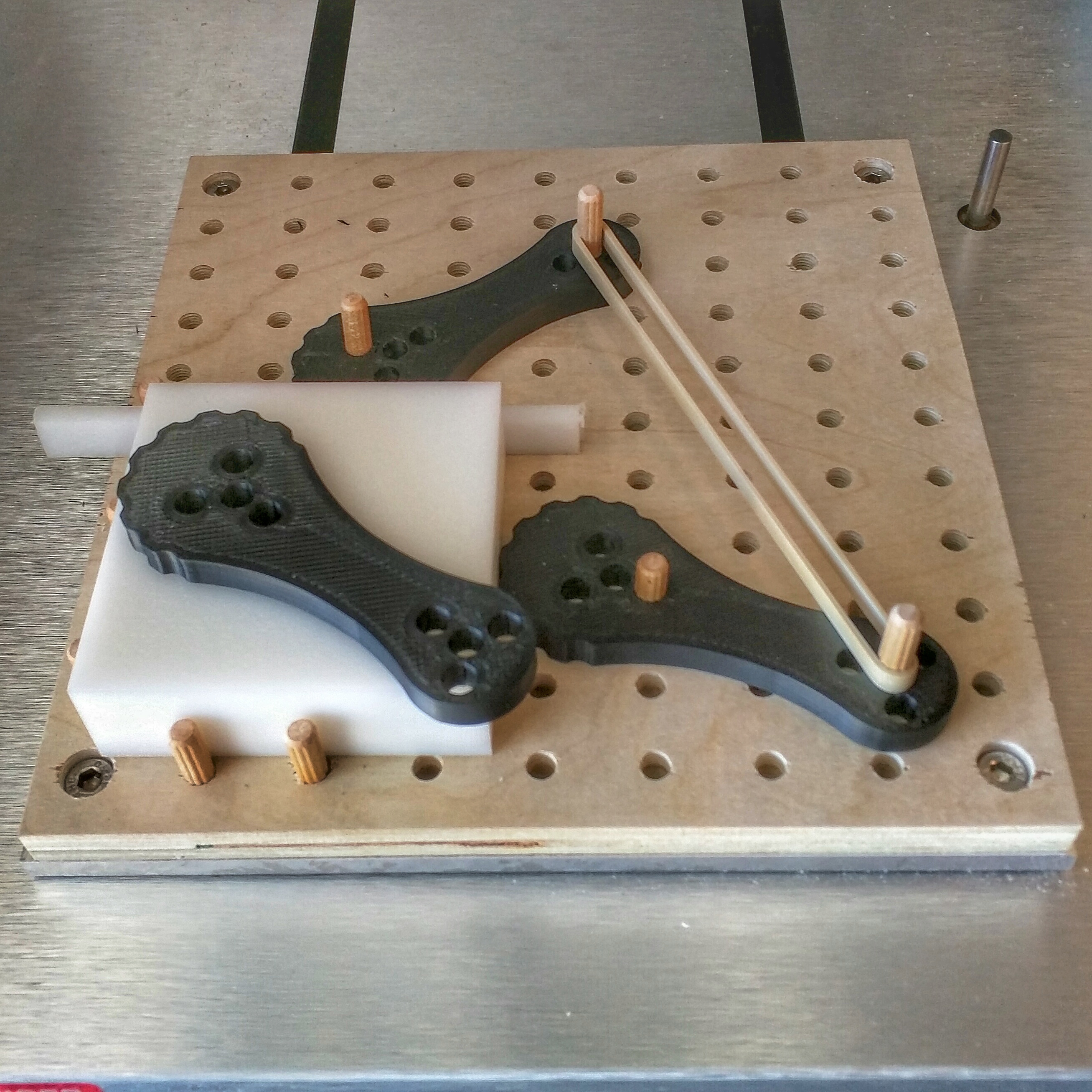
Printed a few cams on my Lulzbot Mini 3D printer…in ABS with 50% infill…just for grins. They appear to hold the workpiece tightly but the proof is in the pudding. I’ll report back on how they work.
2 Likes
On a Machining Centre, I bolt down a 1" mild steel plate so that it’s the exact same size or length and width as the machines clamping table. Then I use a fly cutter to machine the plate flat and then I drill and tap M10 or M12 holes in a grid pattern over the whole plate with 25mm hole centres down to a depth that leaves 2mm of material before breaking through the other side and damaging the machines original table surface, then using a set of letter stamps and number stamps, I punch in next to the holes running left to right with consecutive letters and the holes from front to back with consecutive numbers. Using high tensile threaded rod of varying STD lengths, I screw in rods finger tight that will act as stops for both the rear and 1 side of the workpiece and then I use a STD nut to not only lock the rods but also you can sit the job on them to keep it up off the plate, (you place nuts under the other 2 sides in non-interferring positions ), Make sure these rods are below the job surface, then using longer threaded rods, screw them into the surrounding holes as clamping posts. Once you’ve managed to position and clamp down the job, write down which hole you used for stops as well as the length of rods used and then do the same for the clamp posts so that when the job comes up again, you know exactly where it is clamped down and what you’ll need to do it. You should have something like this written in a book, Stops - a5 + a15 + c14 + h14 and 4 x 55mm rods, Clamps - a2 + a17 + b 14 + i14 and 90mm rods, You clamp down multiple jobs and machine say 6 at a time. It’s the best system I’ve seen and it’s also the quickest to system to set the job next time you have to do them
3 Likes
Very interesting Ray. Do you have any pictures? I’d love to see this!
Really cool… Have to try these out…
Always looking for new ways to clamp…