In Vcarve I use an “allowance” feature to make things fit, but it has been easy to determine whether the cut is an “inny” or an “outty”. I’m not sure how it would work with these box joints.
1 Like
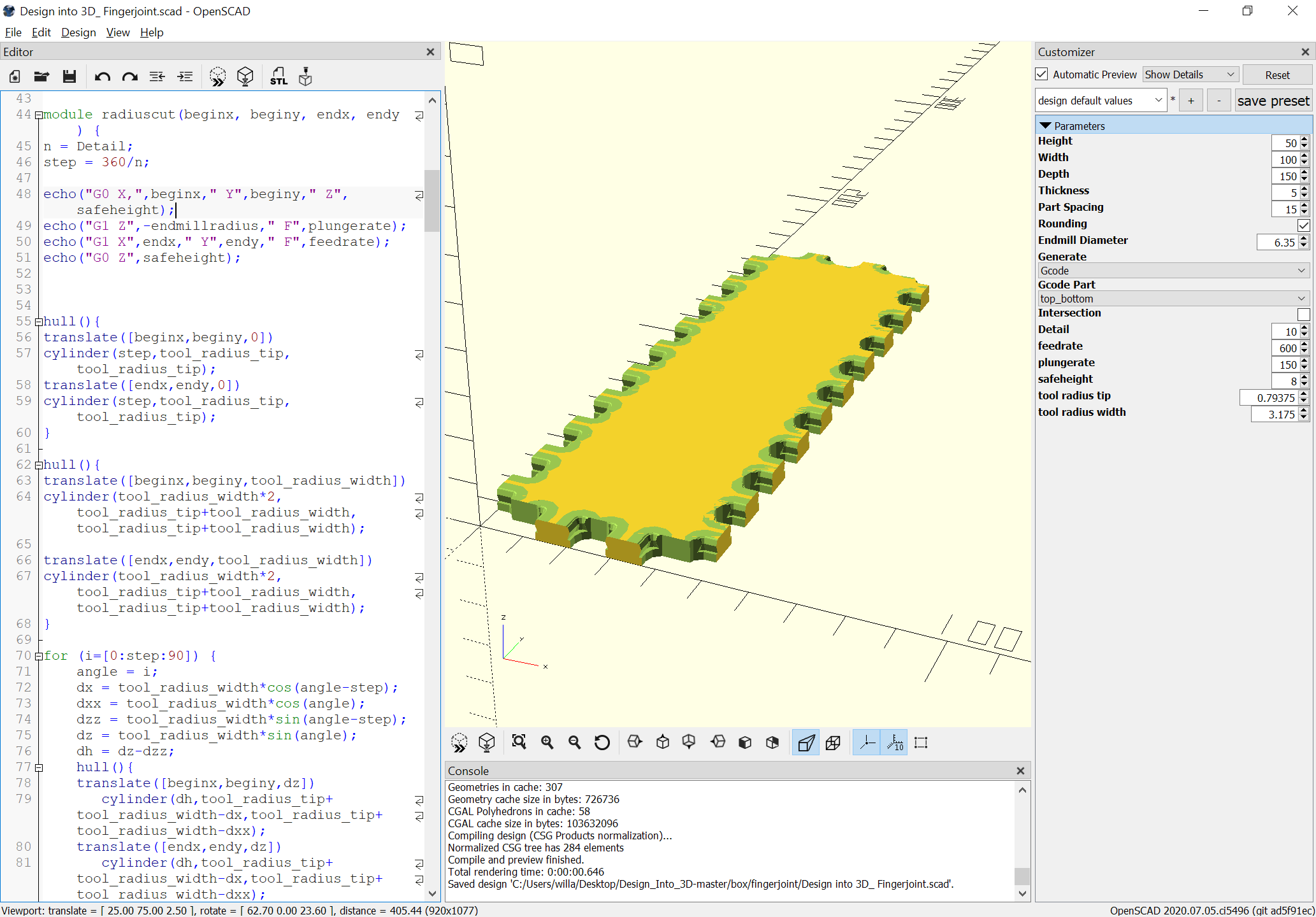
Okay, fixed a problem, and added the rounding along the sides of the top/bottom:
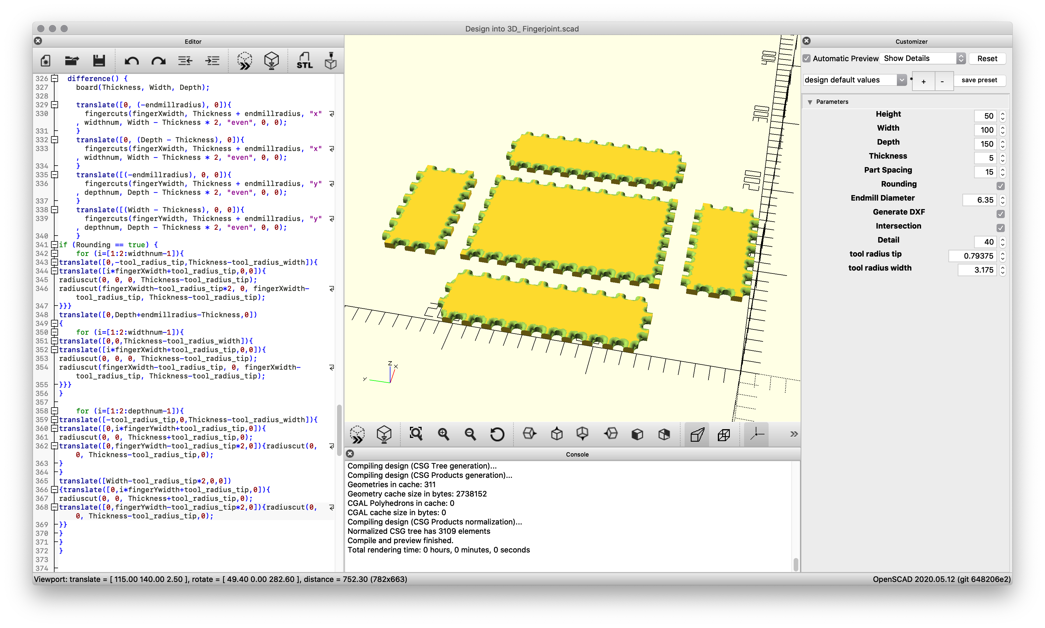
Unfortunately, performance isn’t much better on my MacBook, so sort of stuck.
The tool movement which would be needed is simply a series of lines, but OpenSCAD won’t draw those so that they can be exported to a DXF. It wouldn’t be so bad if there was just a way to write numbers out to a file (other than the JSON used for customization).
File seems fine from a 3D modeling perspective:

Design into 3D_ Fingerjoint.scad.zip (2.5 KB)
See further discussion on /r/rapcad and /r/openscad on Reddit (the OpenSCAD forums are down at the moment)
Unfortunately, there isn’t a way to use OpenSCAD to create a DXF ready for cutting with a radiused endmill such as:
https://www.amazon.com/gp/product/B00Q8M1SRS
Fortunately, just a straight line move is needed, so it ought to be workable to just define it as a square endmill, have it plunge and then make the cut and lift out.
We start by exporting the flat design:
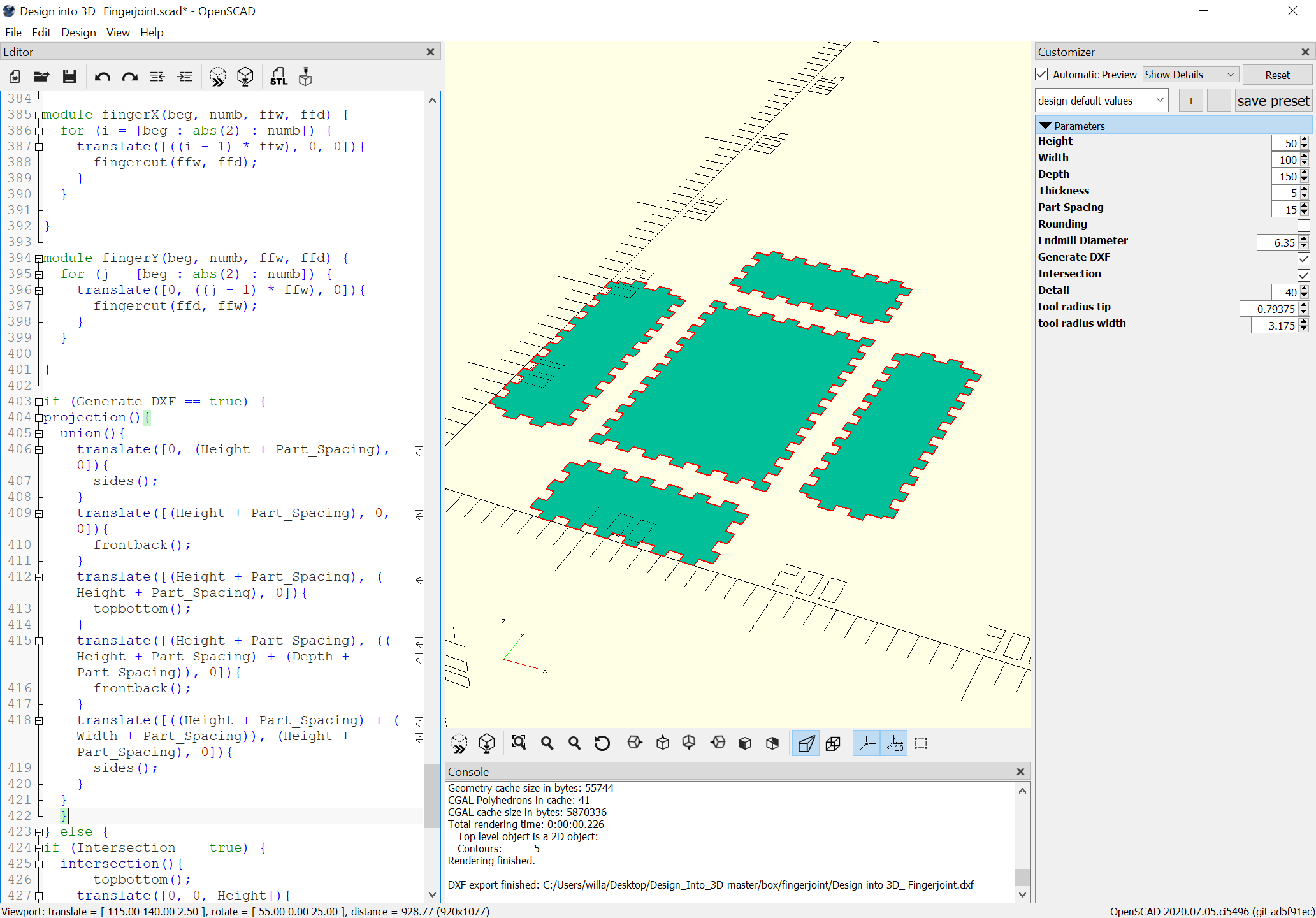
(hopefully the radius of the endmill will reasonably match the radius of the cut)
then import the DXF:
Design into 3D_ Fingerjoint.dxf (29.7 KB)
Assign thickness to match the material (5mm), then a profile cut, then we have to define the radiusing tool.
Drawing up the tool reveals a tip diameter of 1.5875mm:

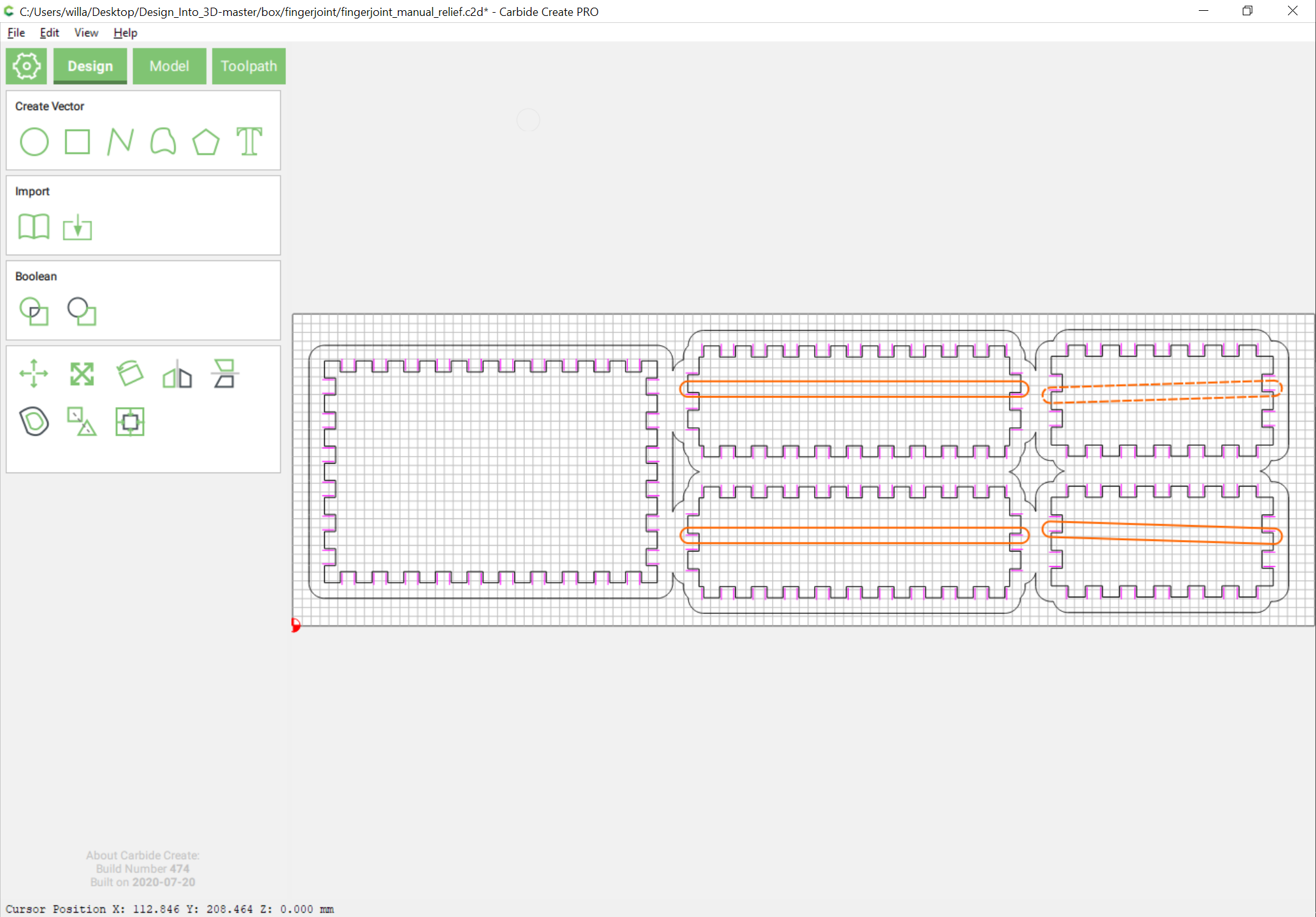
Defining a tool of that diameter we then have to work out the placement of the toolpath — working with a pair of circles of that diameter and drawing from center–center we arrive at:
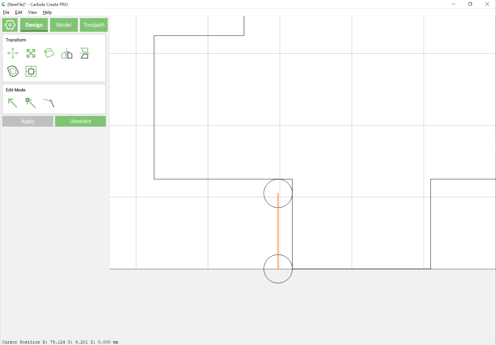
where the open (magenta) line should be the cut we want made at a depth of the radius we want cut.
Except of course for the matter of how to open up the box — for hand-held boxes it’s fine to saw them in half to open them (if a bit nerve-wracking), for CNC, it’s easier to just design it into the file.
Rather than just a horizontal opening we’ll add some visual interest by making the lid open at an angle — since it would be jarring to have a horizontal cut along the front edge we’ll want to specify an angle where we can cut out a matching slope along the front edge (since we can’t flip the back over we’ll accept a straight edge there).
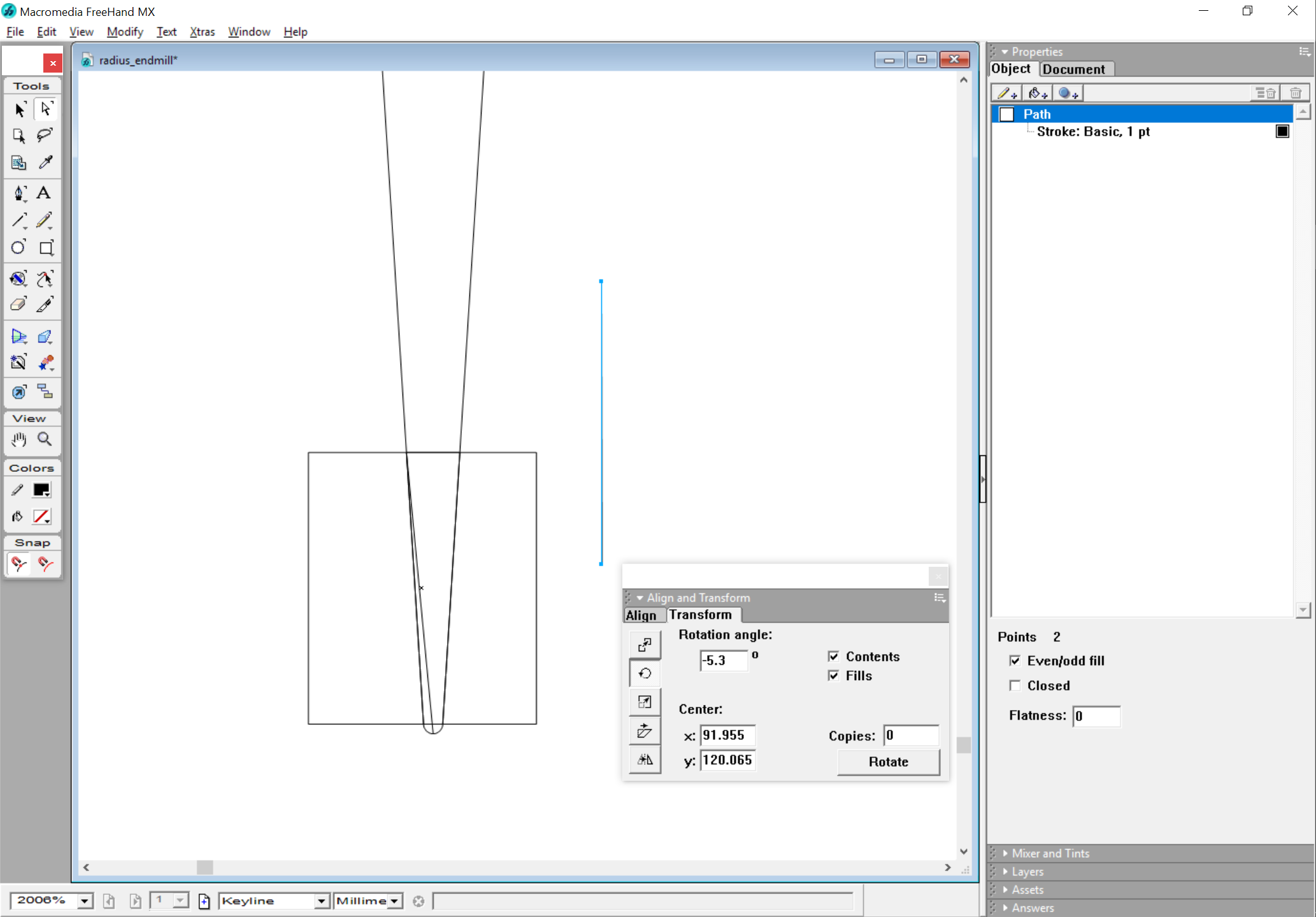
Next we have to draw up the tool and how deeply it will need to cut to make the desired angle and enter it.
Helps if we rotate at the correct angle. Seems the endmill is defined in terms of taper and not nominal angle:
Next, we re-rotate things for the sides and box.

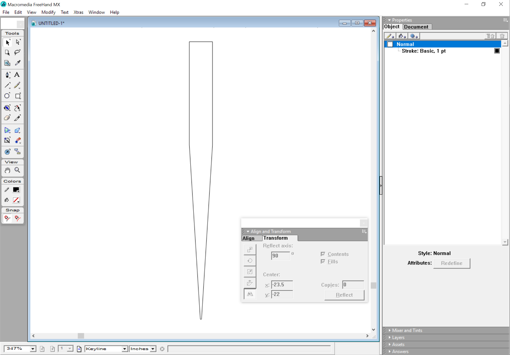
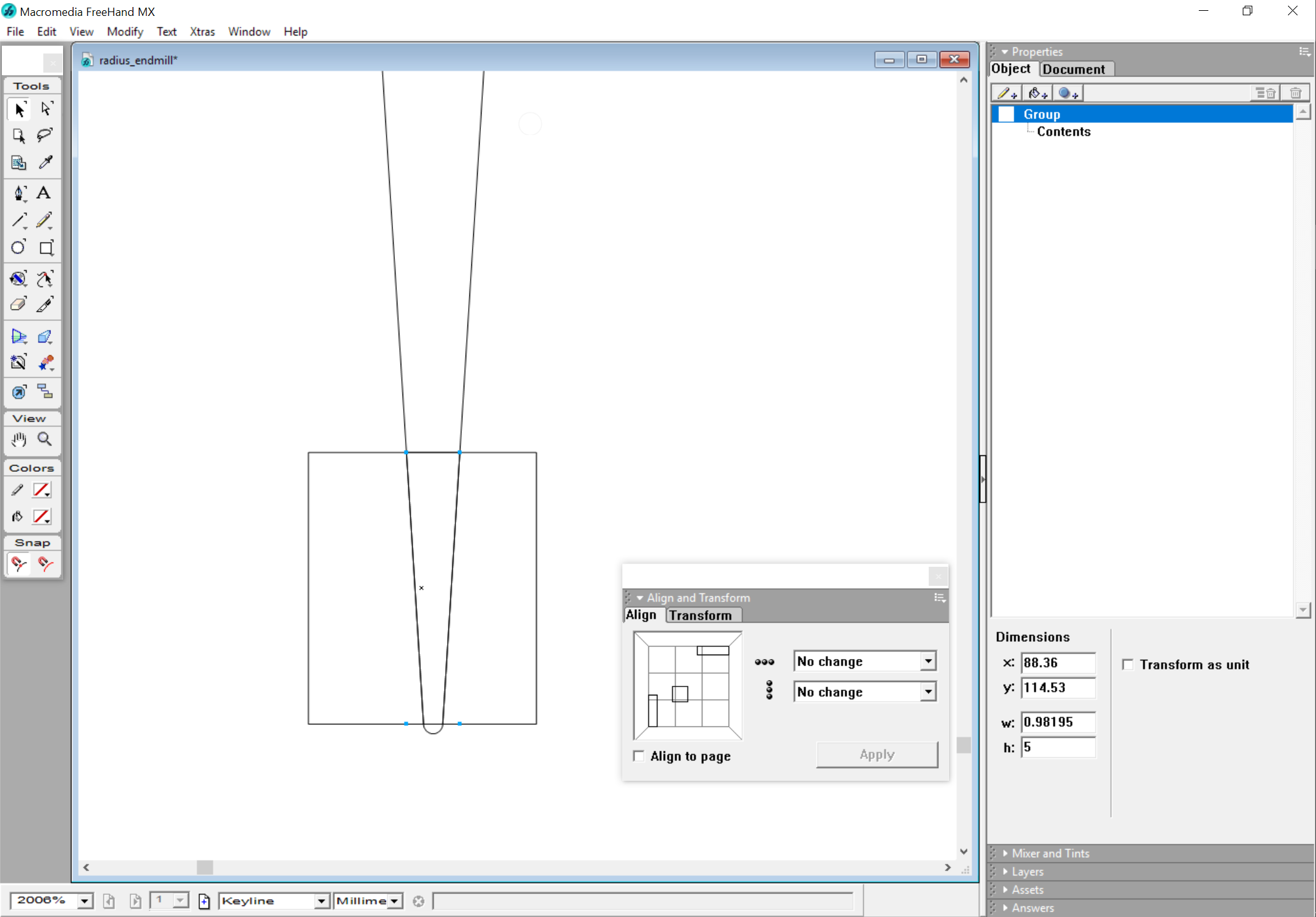
In order to make a through cut so as to get the 3.6 degree angle we would need to cut an 0.98195mm wide design:
using a 10.6 degree V endmill:
Except of course the angle is only right for the cut from the inside at either the top or the bottom depending on if the piece is at the front or back so that the wrong pieces have to be cut as a second setup from the other side or left proud and filed off to the correct angle.
Working on directly getting G-Code out.
EDIT: wired up the gcode output part selection and fixed the top/bottom and improved the G-Code generation:
Design into 3D_ Fingerjoint.zip (2.3 KB)
which puts lines such as:
ECHO: "G0 X0 Y0 Z8"
ECHO: "G1 Z-3.175 F150"
ECHO: "G1 X0 Y4.20625 F600"
ECHO: "G0 Z8"
ECHO: "G0 X6.89856 Y0 Z8"
ECHO: "G1 Z-3.175 F150"
ECHO: "G1 X6.89856 Y4.20625 F600"
ECHO: "G0 Z8"
into the console which can be extracted with a command line option — now just need to get someone to afford a menu command to write out only a filtered version of the echoed text and customize the file extension and it’s good to go.
Following as this is very very interesting! Just downloaded OpenSCad to ty it also. 
Thanks!
FWIW, I’d suggest starting with BlockSCAD:
I tried to document this sort of workflow pretty thoroughly at:
and did put up a test cut in a different thread:
Hopefully I’ll get another top/bottom cut this evening and then put one together.
1 Like
Wrote up a detailed examination of this at:
https://willadams.gitbook.io/design-into-3d/fingerjoints
Here are two Carbide Create files:
carbidecreate fingerjoint vertical parts.c2d (65.1 KB)
carbidecreate fingerjoint vertical cuts.c2d (39.8 KB)
They want a #102 or other 1/8" endmill (I’ve been using a downcut) — actual setup and cutting photos presently.
1 Like
While one could carefully measure the fingerjoint width and then adjust the mechanism, it’s easier to just cut a small fixture to hold the boards in their relative positions:
which is ready to cut once unioned:
1 Like
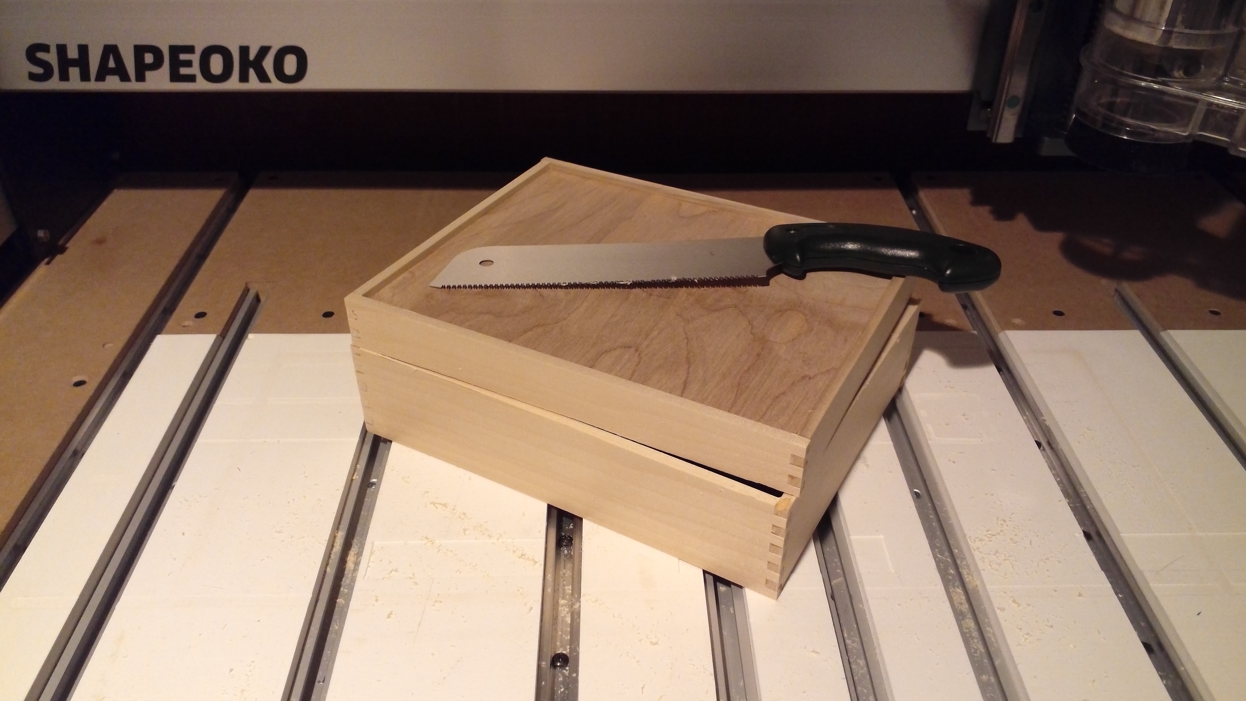
It’s always a bit nerve-wracking cutting boxes apart, but the groove helps a lot, and isn’t too much wider than the saw kerf:
1 Like
Here are the files for this box:
top and bottom.c2d (10.2 KB)
carbidecreate fingerjoint vertical cuts_3488.c2d (169.7 KB)
carbidecreate fingerjoint vertical parts.c2d (89.5 KB)
3 Likes
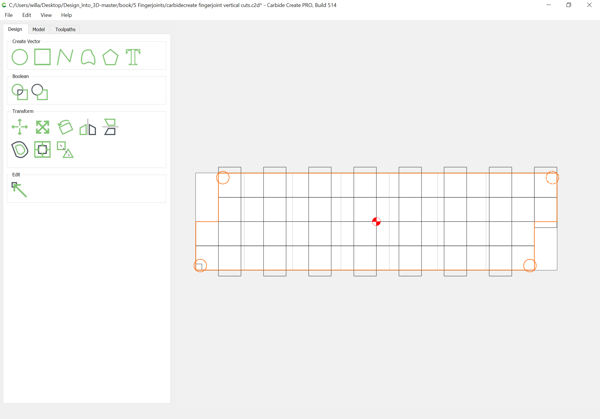
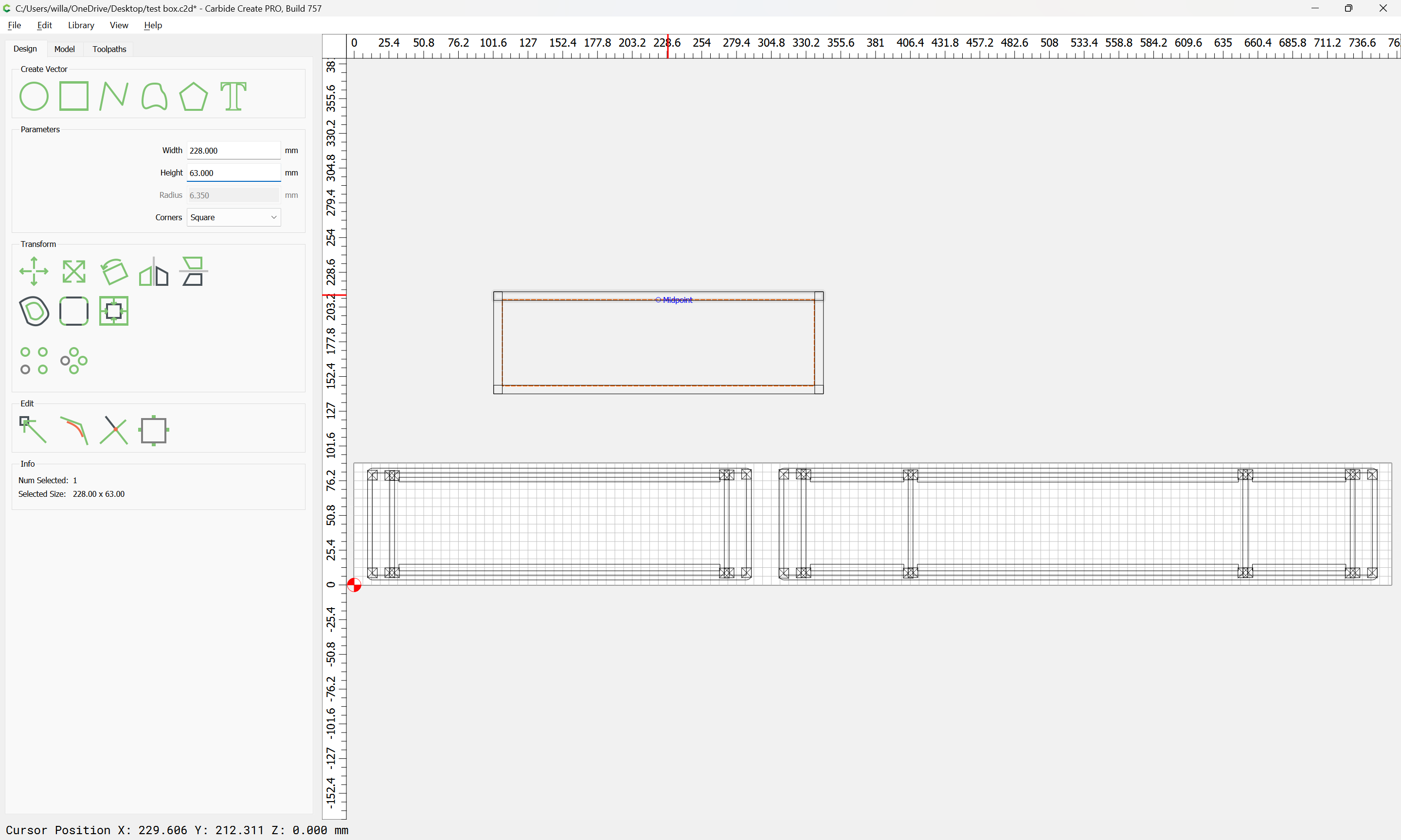
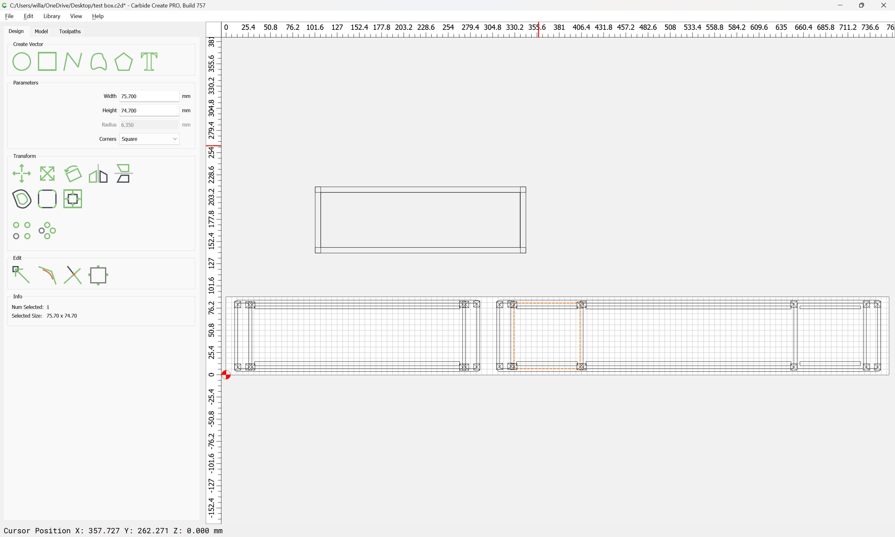
Revisiting this, I believe it can be simplified by using a centered toolpath to cut the stock ganged up at the front of the machine.
Just insert a spacer which has the same (or slightly less) thickness than the stock (and greater than the diameter of the tool used and set up the job to be equal in width to the height of the box and depth equal to stock thickness * 5:
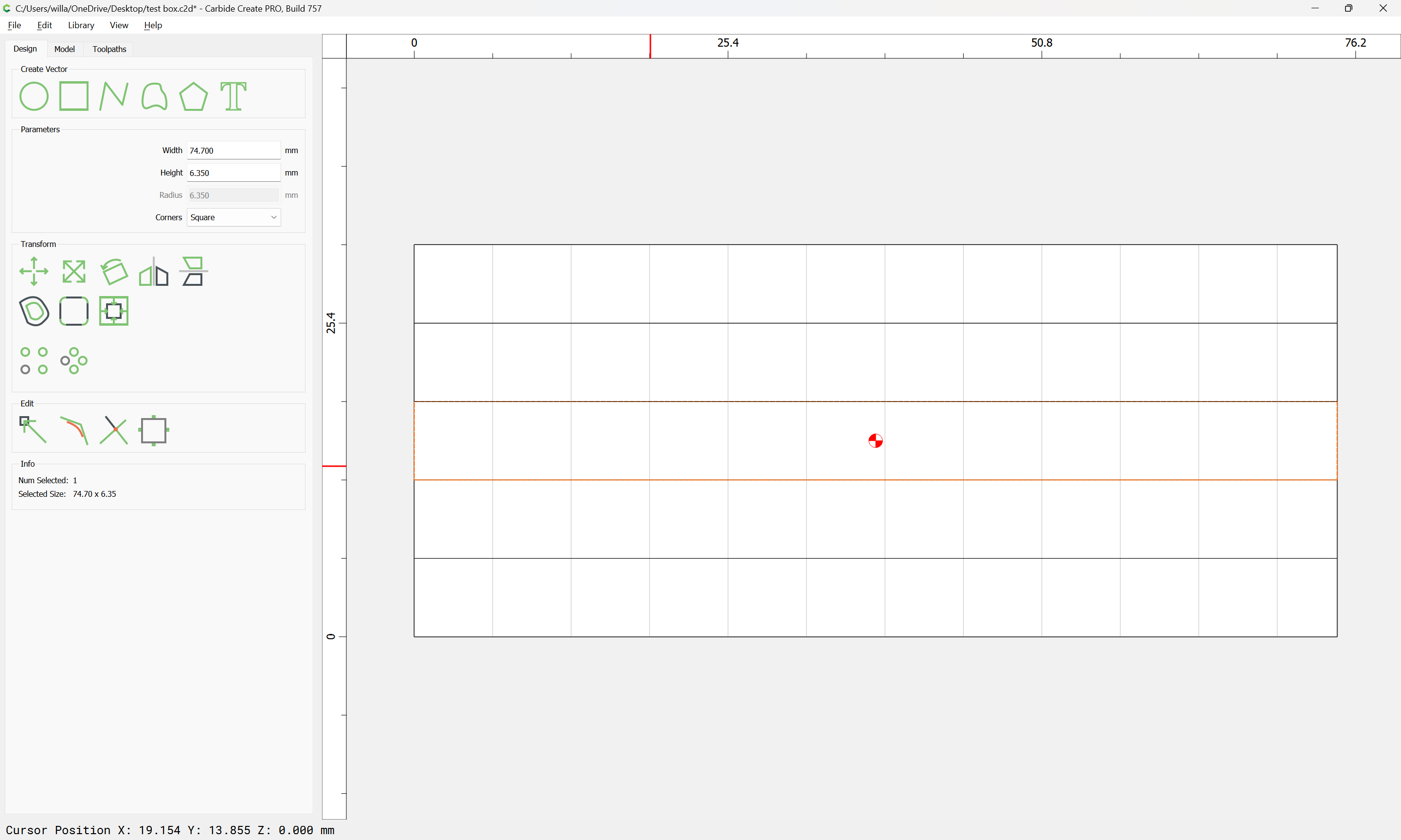
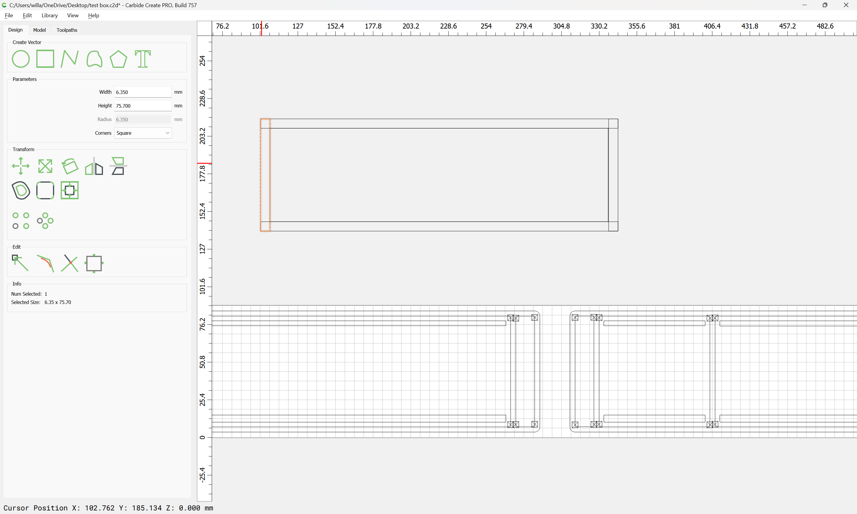
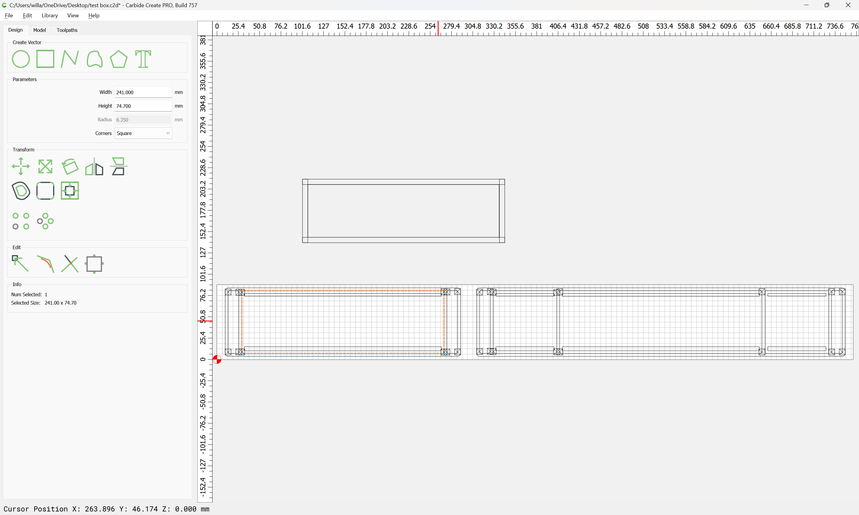
Then divide the box height by the diameter of the tool to be used:
74.7 / 3.175 == 23.5275591
Round down to some reasonable odd number, so 23, then divide that into the box height to get the height of the fingers:
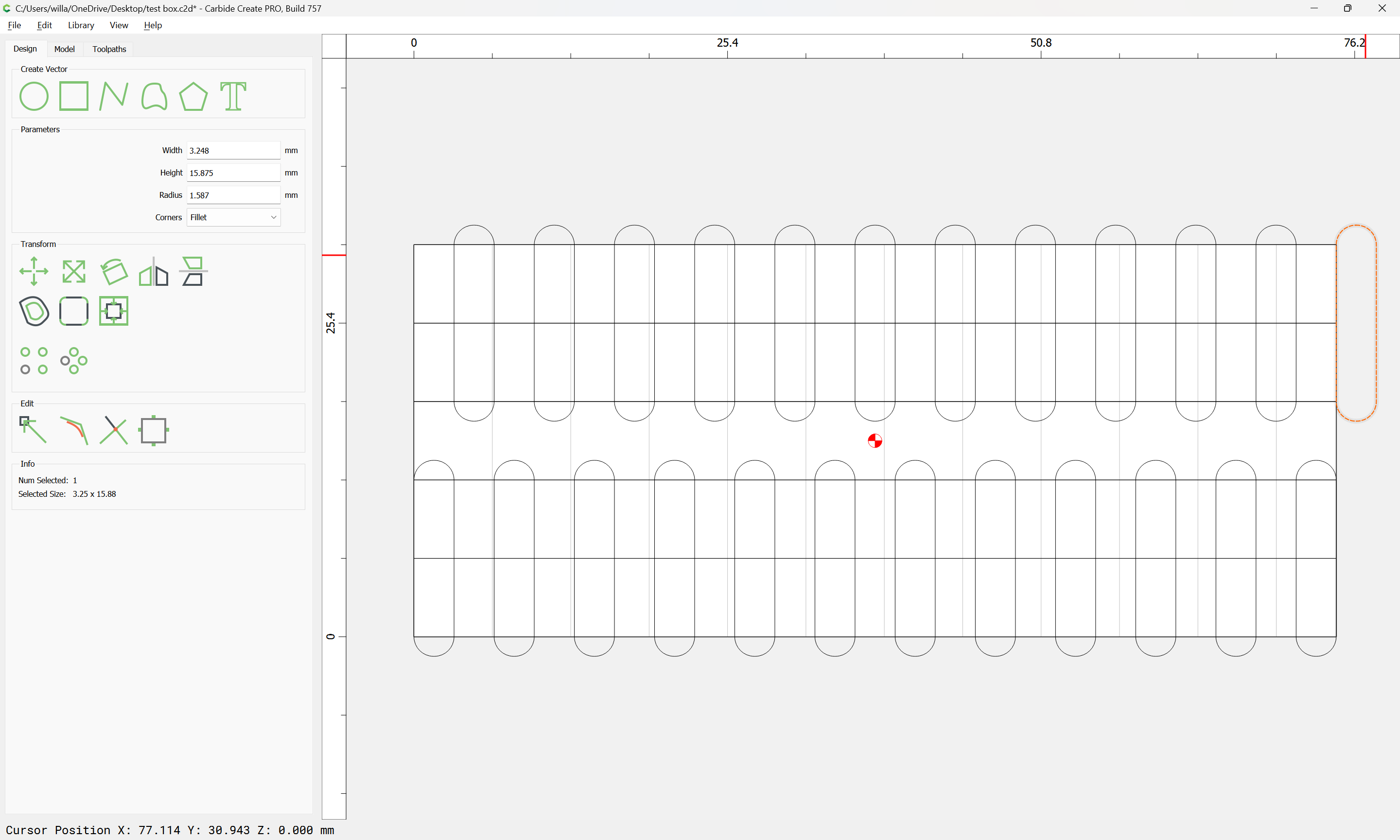
74.7 / 23 == 3.24782609
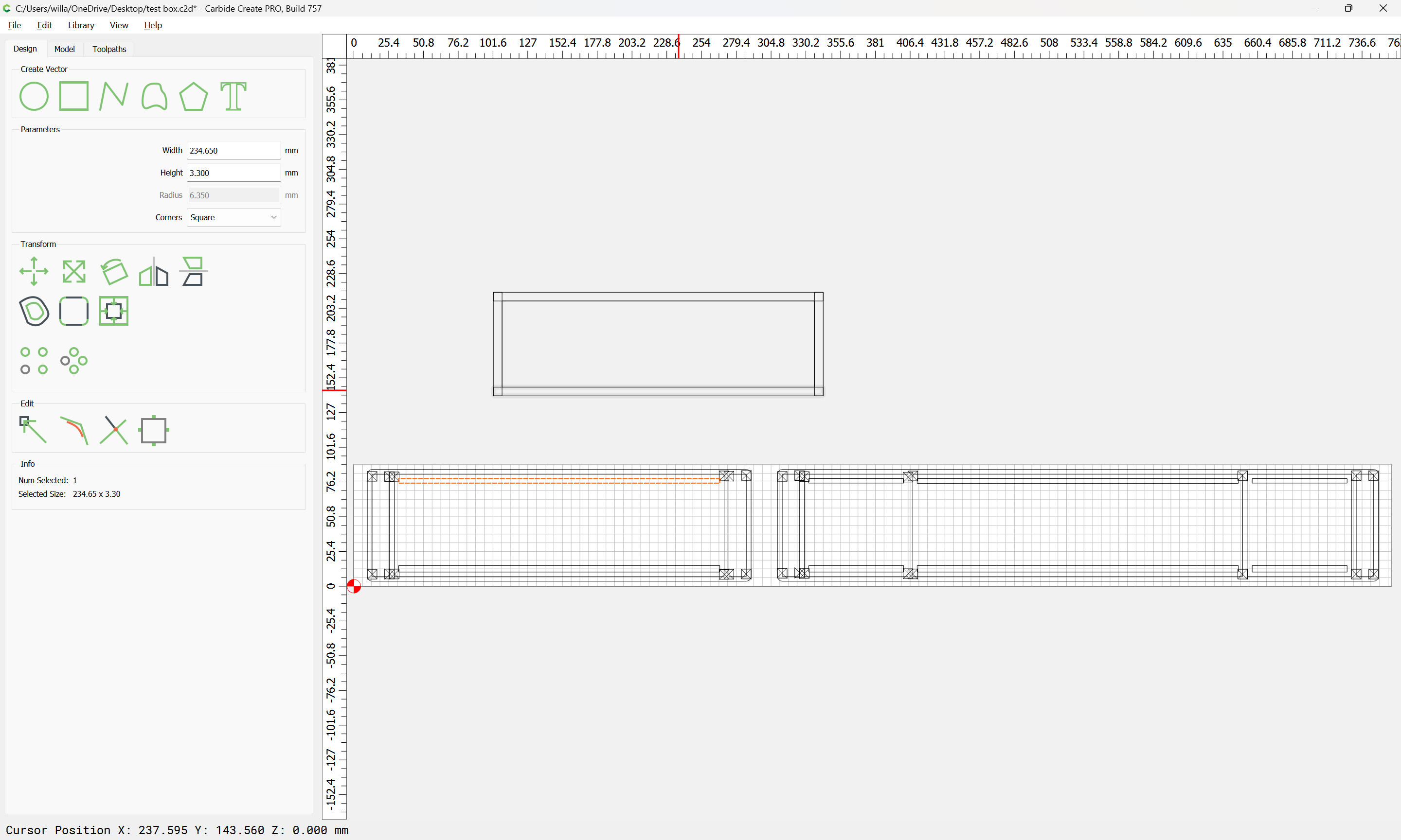
Create a rectangle which has that width and a height equal to twice the stock thickness plus tool diameter:
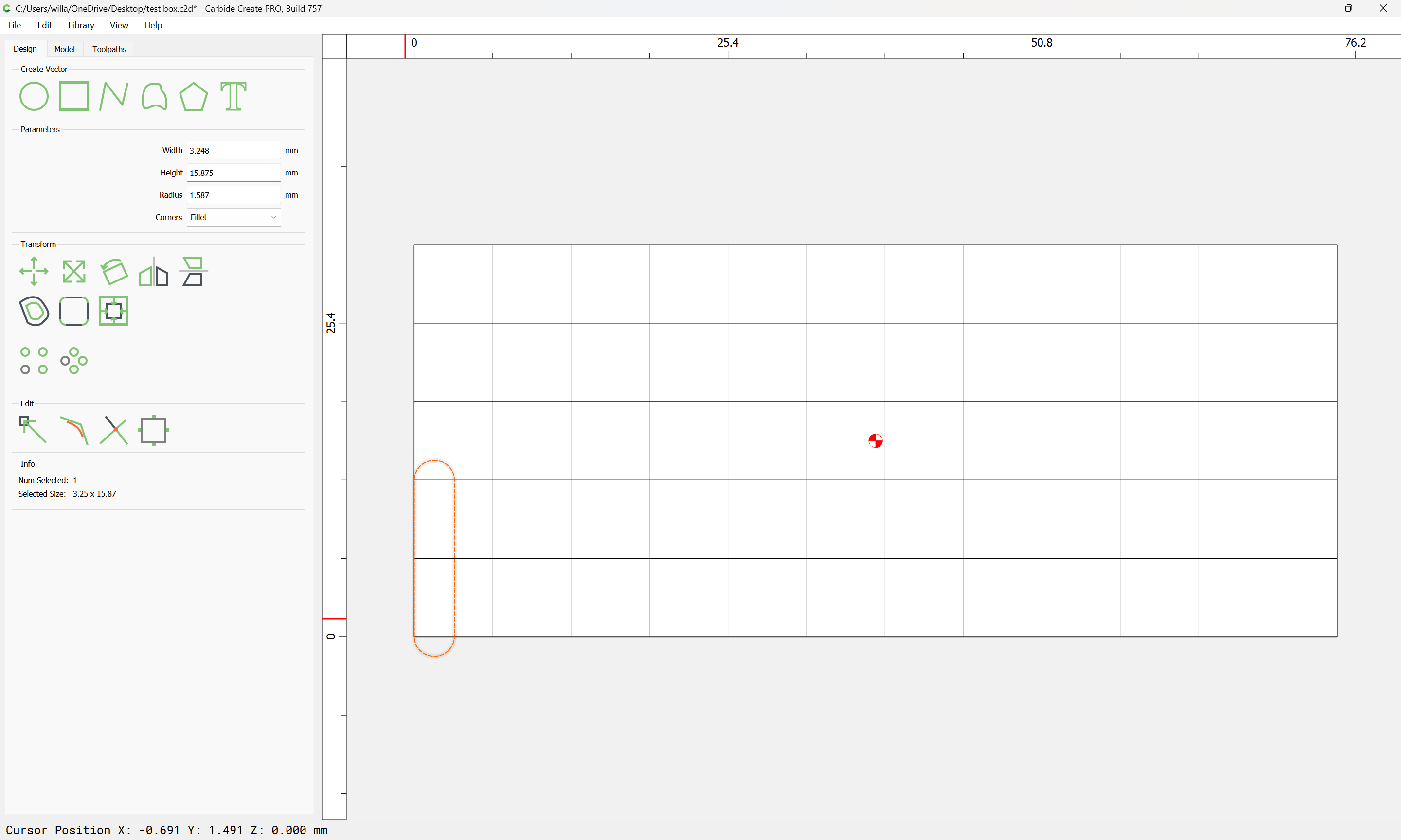
Duplicate it and position the duplicate at the top, box joint width in:
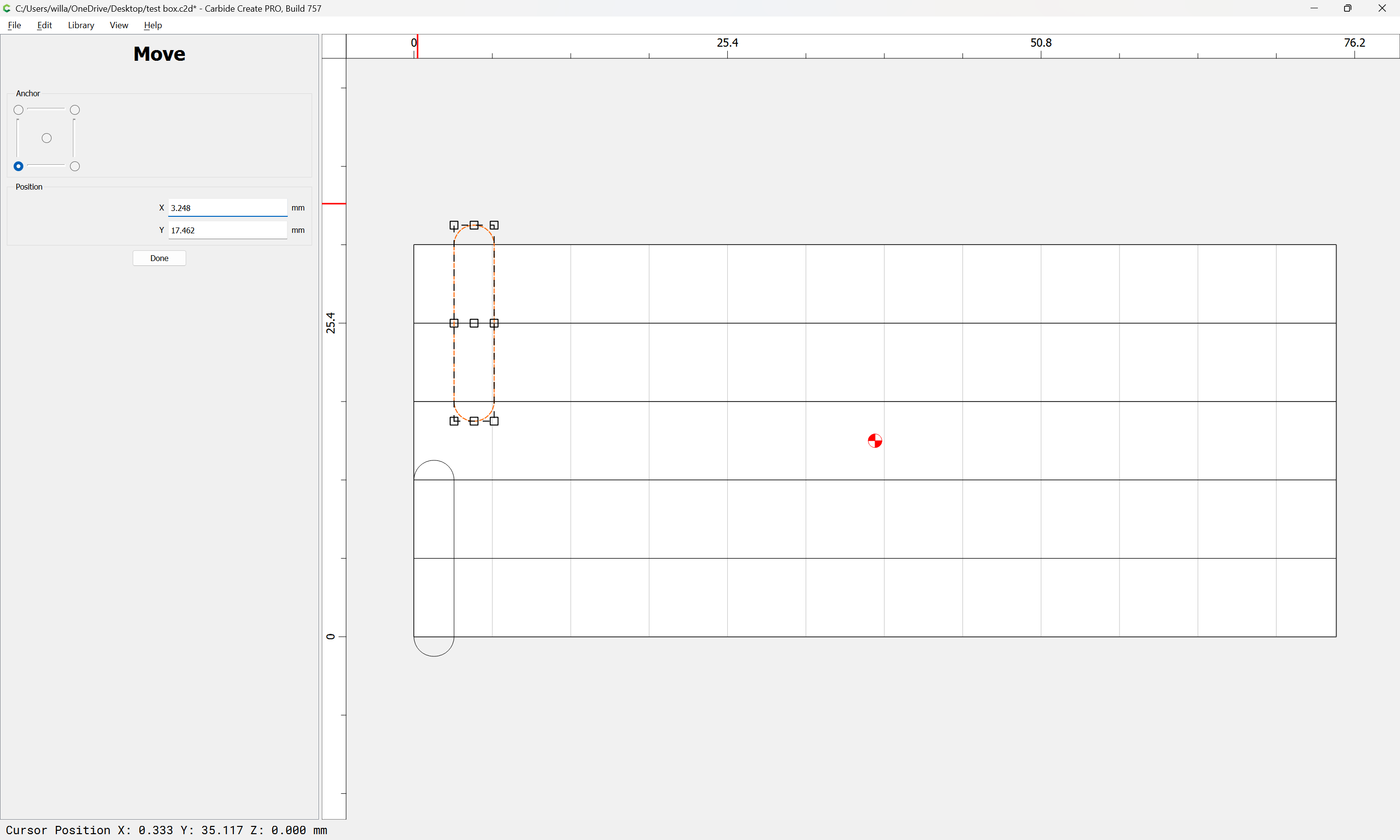
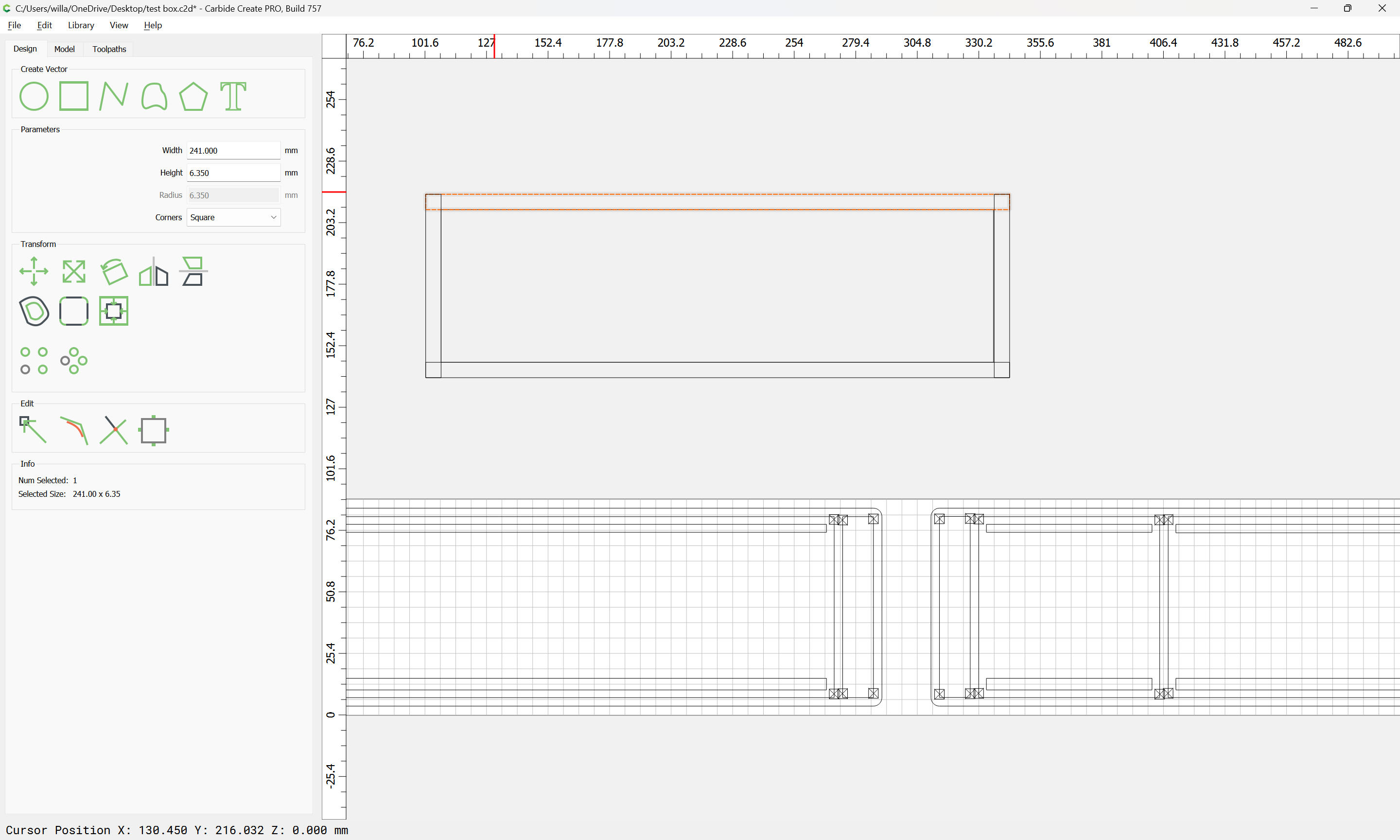
Select the twain and use Linear Array to replicate them:
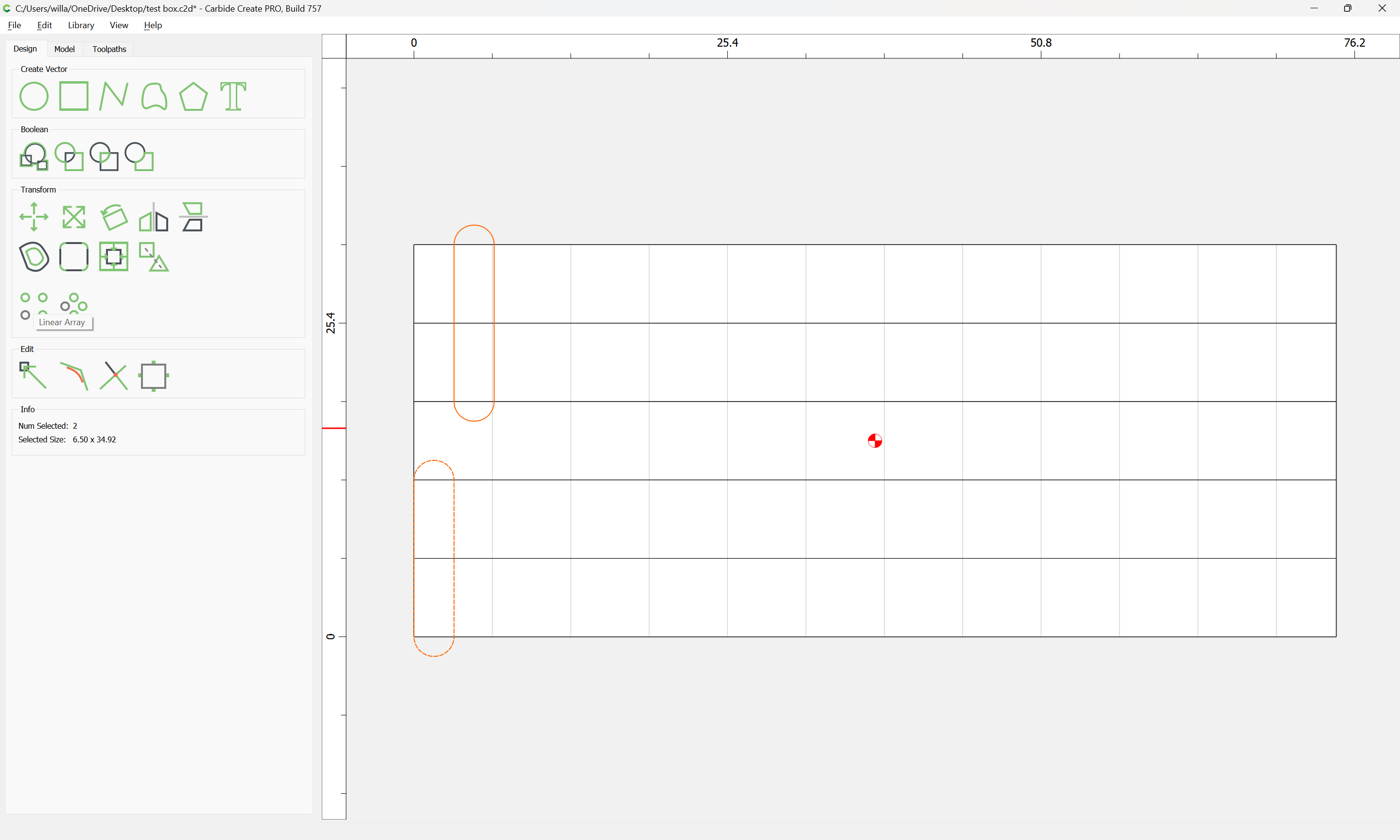
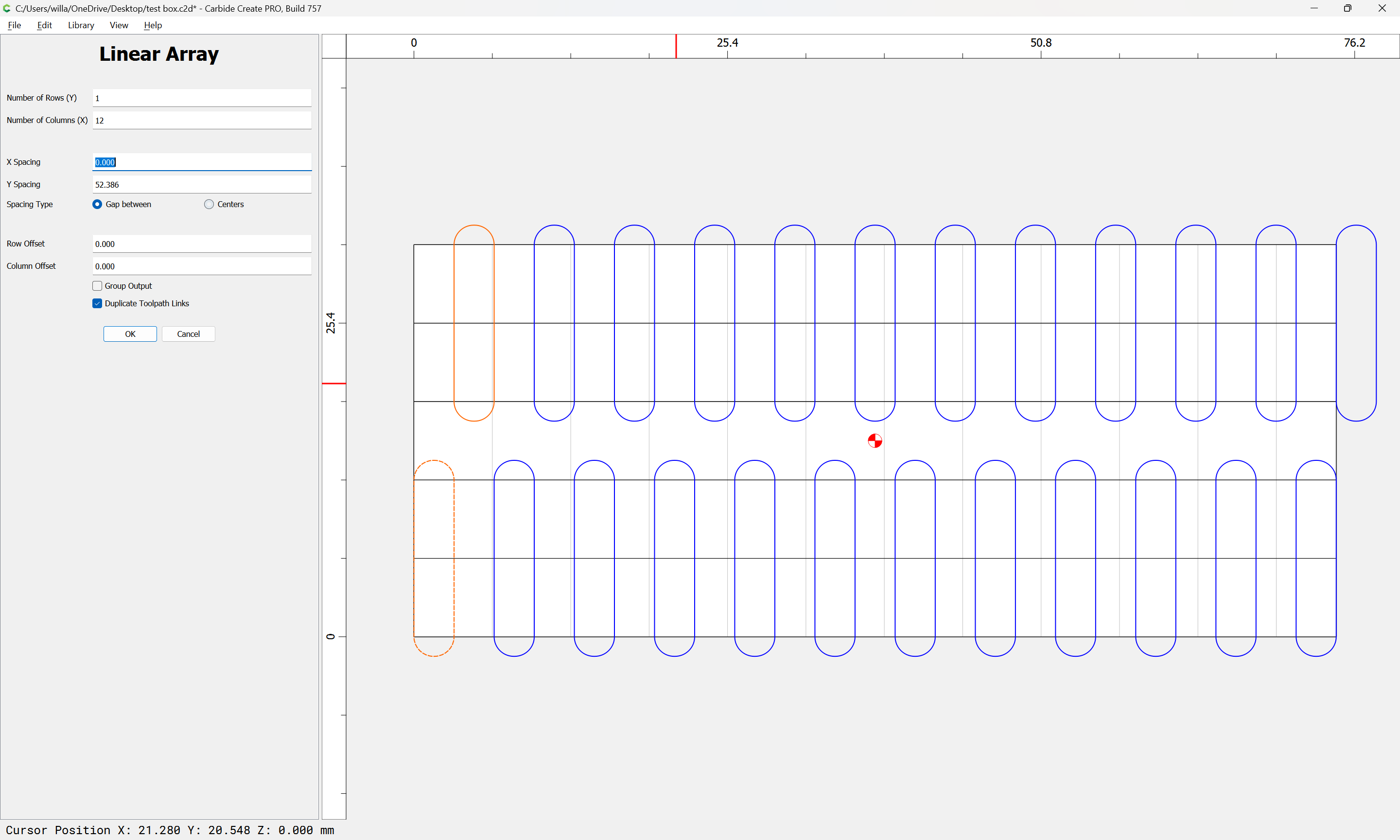
Delete the redundant one:
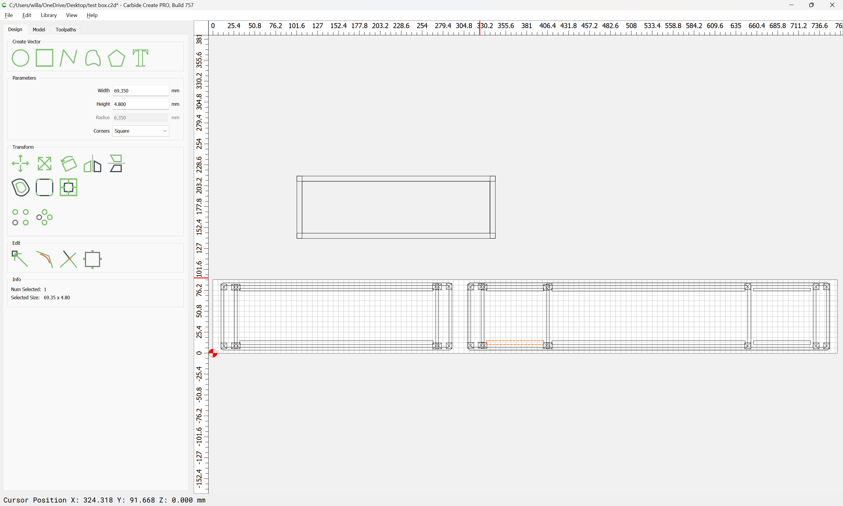
select:
and assign a toolpath to cut to the stock thickness plus glueline:
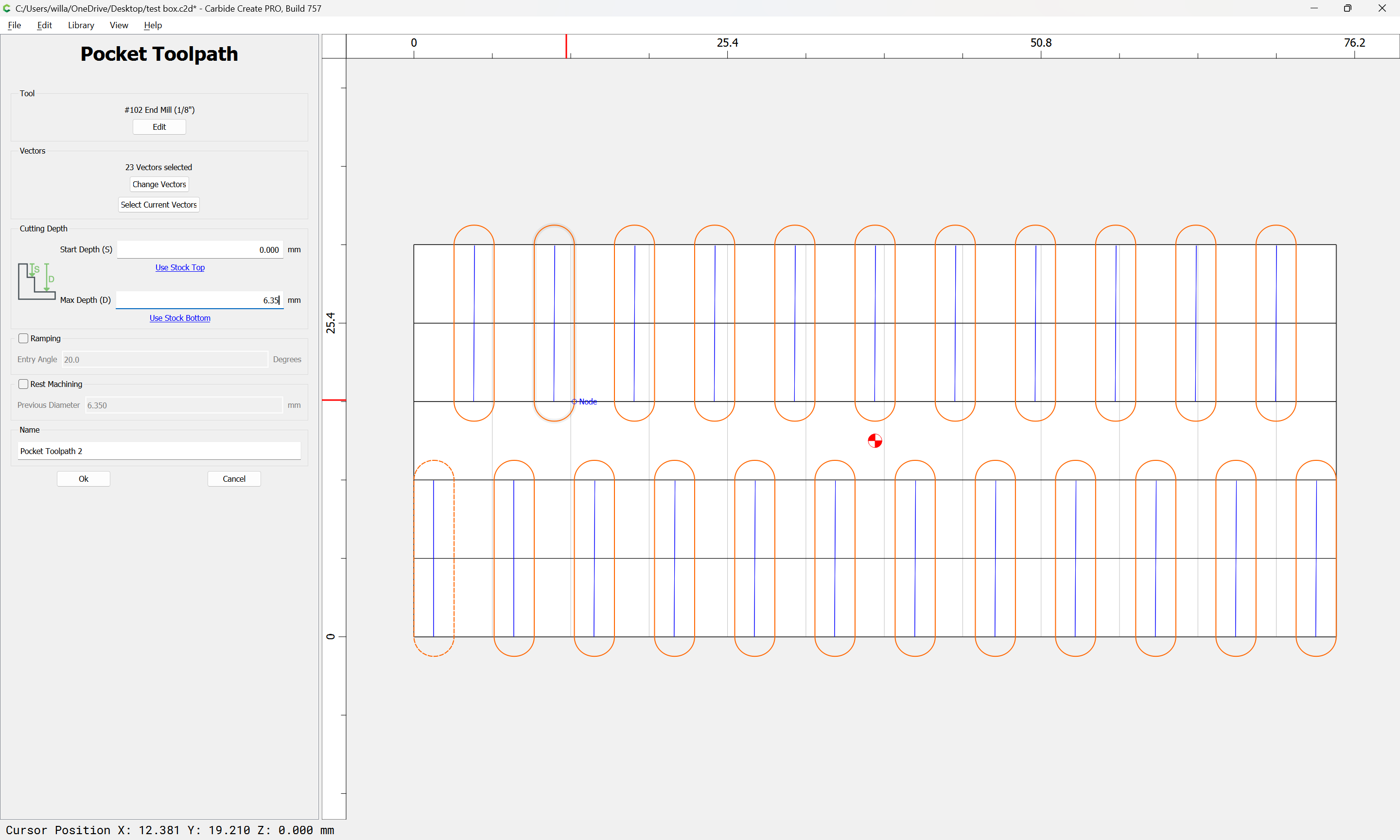
(optional, increase the two end pocket widths to ensure a clean cut)
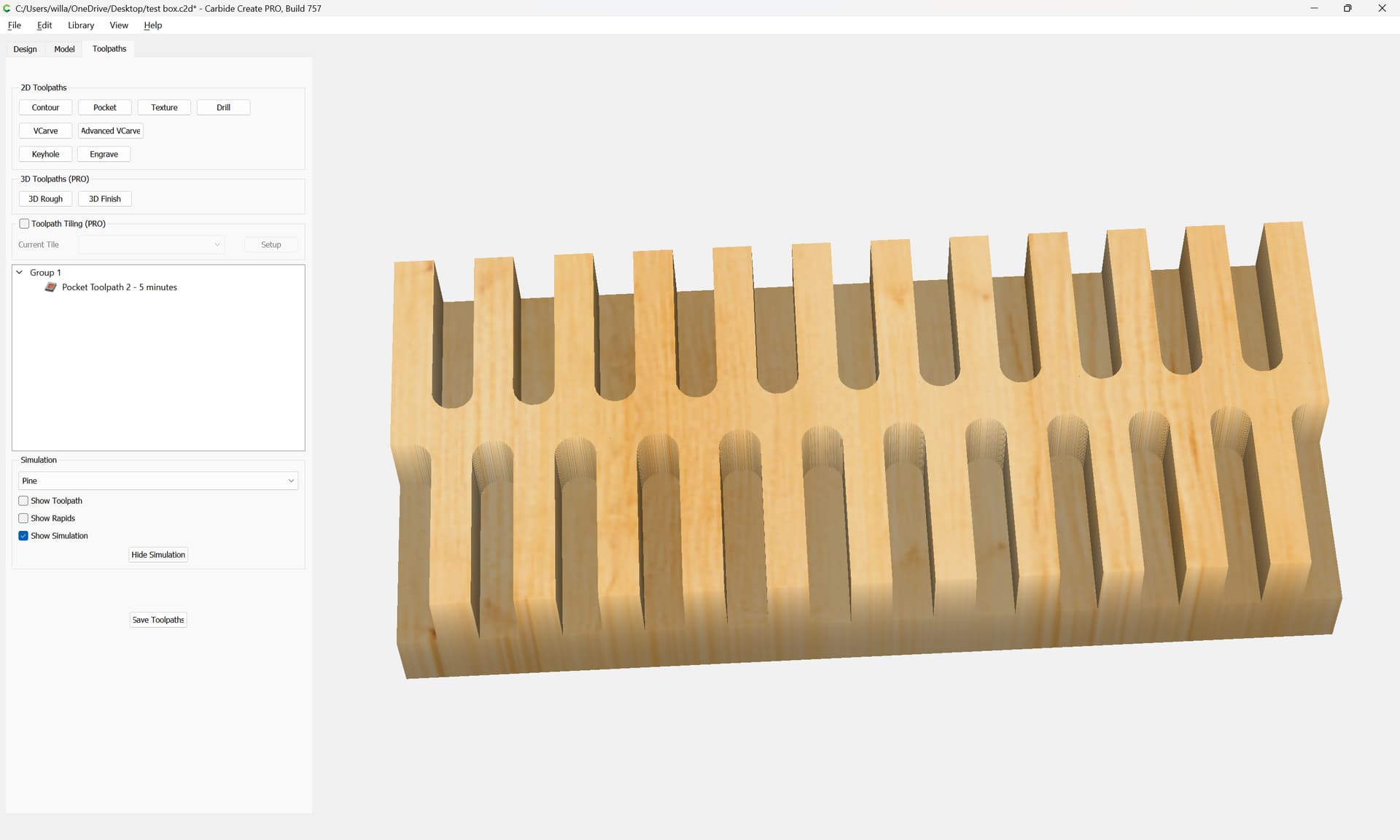
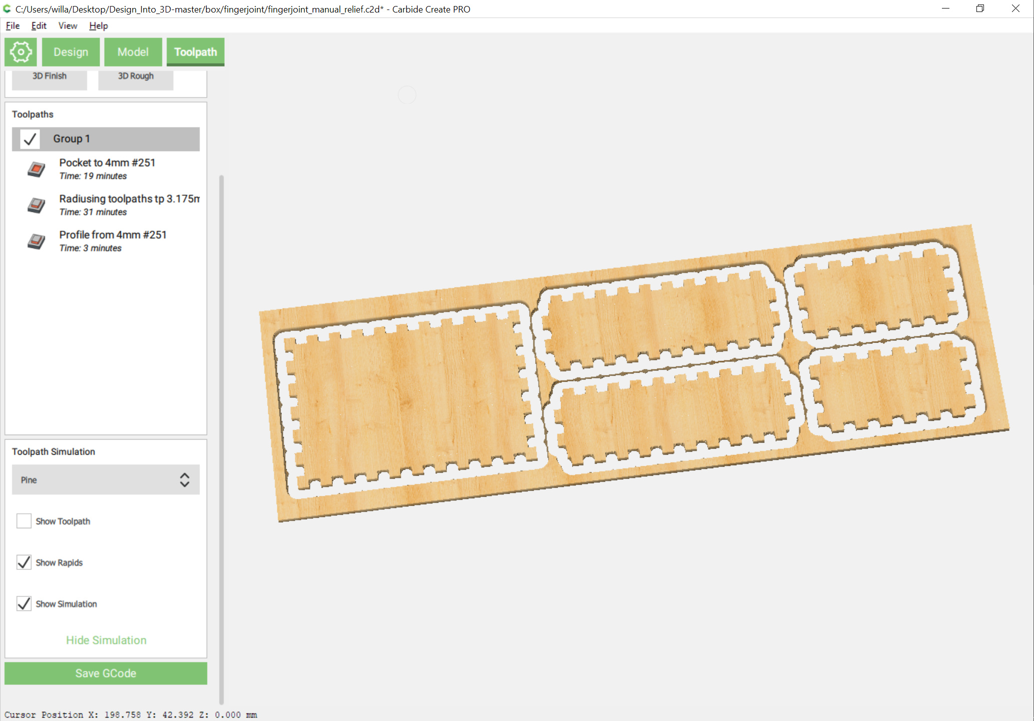
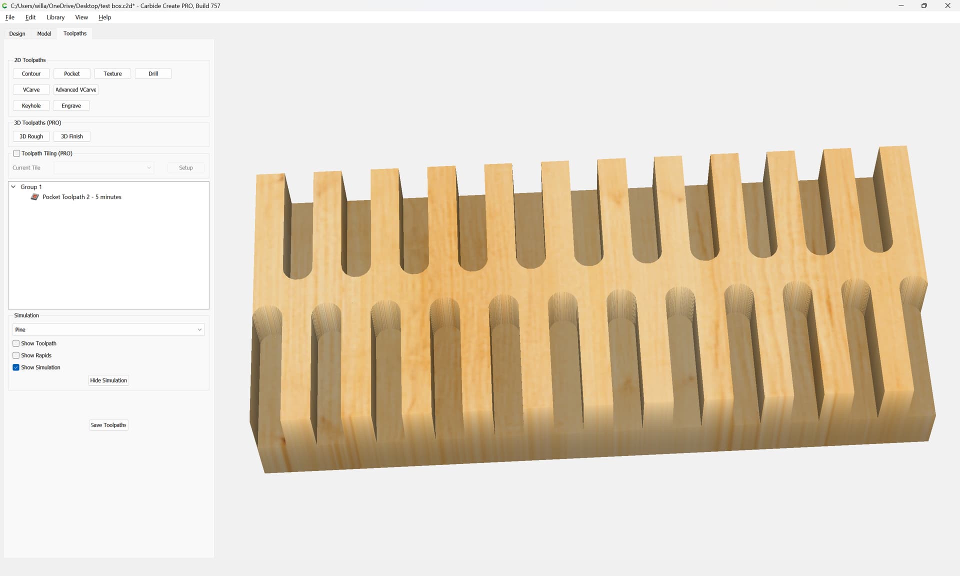
Then it’s simply a matter of cutting the parts, including any interior features, stacking them up with one piece in the middle as a spacer, and sacrificial boards on either side and then cutting them out.
1 Like
For the parts themselves, it is a simple matter to work up the dimensions (either interior or exterior — we’ll use interior):
and then add the stock thickness representing the box as viewed from the top around it:
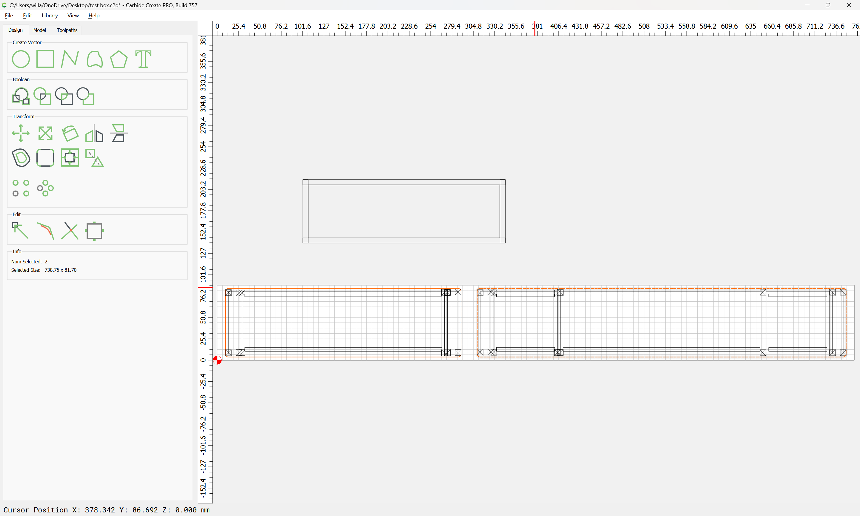
Draw up the parts:
Add in geometry for the lid/bottom:
Add parts for spacers:
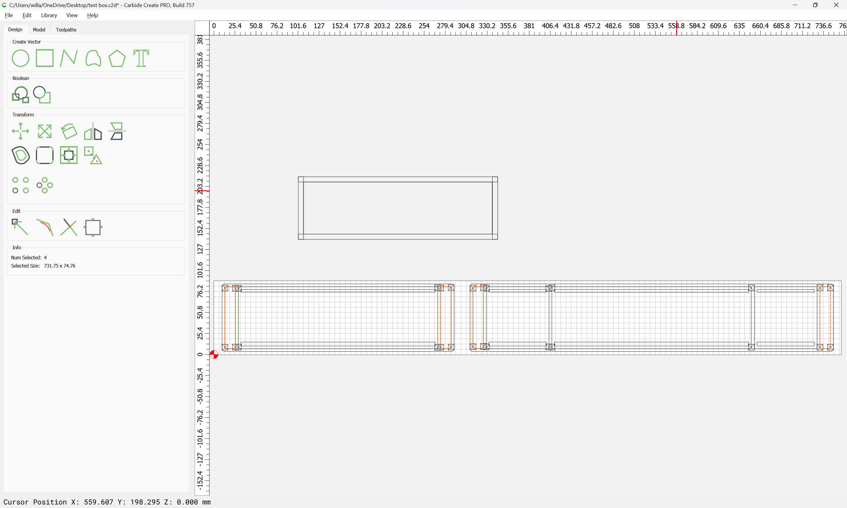
Add tabs:
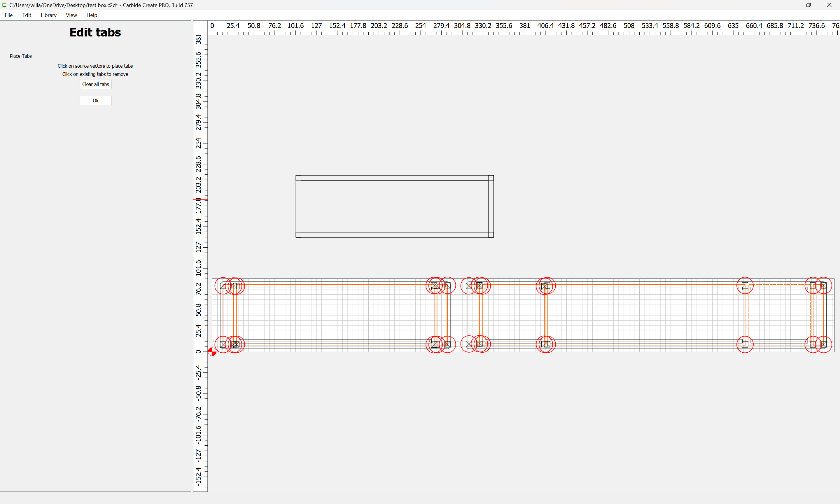
and surrounding geometry to cut as a pocket down to tab height:
(using two pieces of stock so as to use up some scrap)
and then assign toolpaths to arrive at:
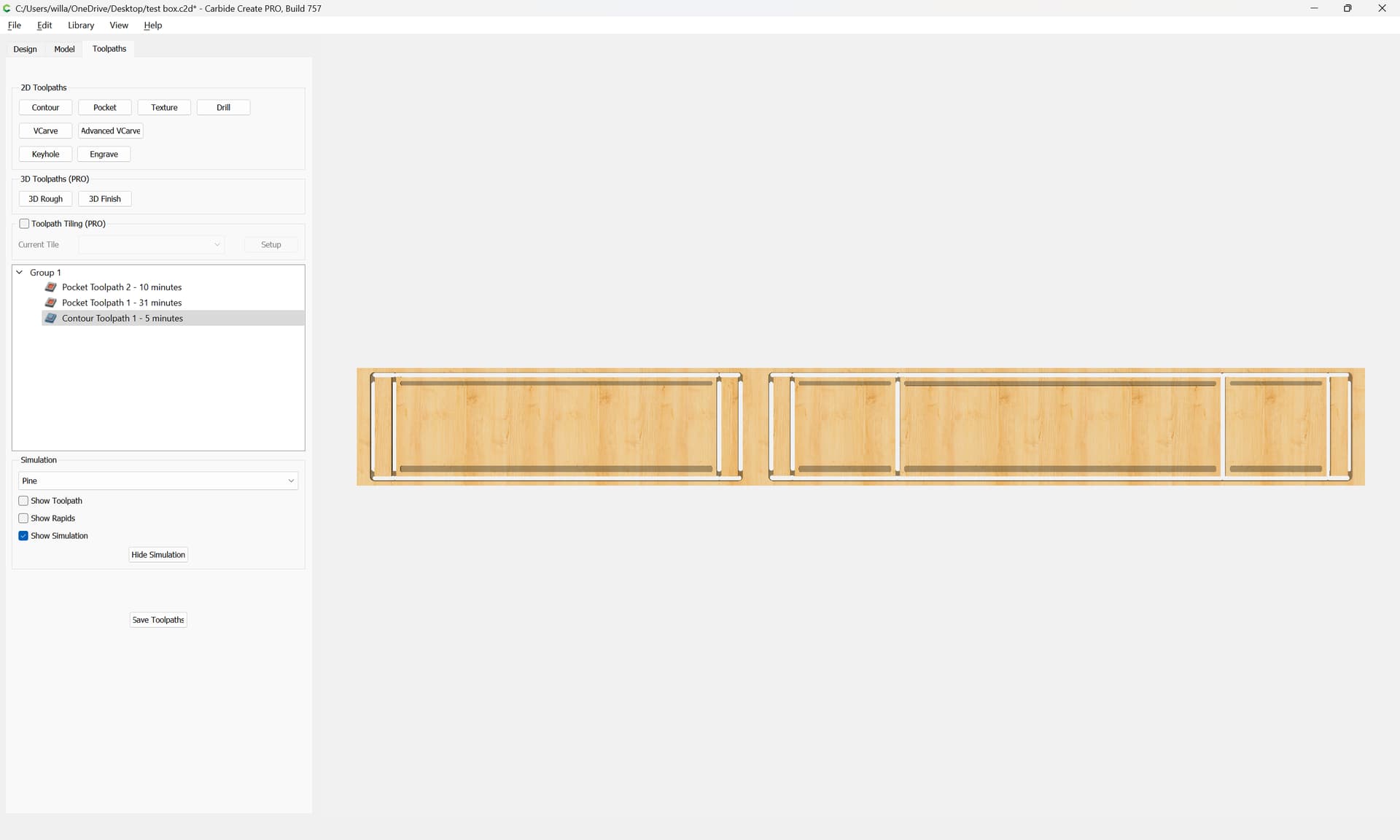
2 Likes