Don’t feel a need to learn these, and they’re not quite software packages.
JSON == JavaScript Serial Object Notation — it’s a format for storing data
Lua — this is a programming tool often used for scripting and embedded in other tools, in this, inside TeX
TeX — this is a mathematical typesetting tool, arguably obscure, and not much used outside of that specialty, though I’ve used it for pretty much anything and everything
METAPOST — this is a programmatic drawing tool derived from METAFONT which was developed to make fonts for TeX — it’s actually a library inside of luatex
Arguably it’s one file format, and just one software tool — I’m hoping for this it will all be turnkey, though I’m not having as much with JSON as I’d hoped (trying to figure out why it’s not importing the file). EDIT: JSON file is importing and exporting (had an extra comma).
which just leaves adding in the divider(s), labeling the parts, colour-coding the paths, working up the fixture and writing up the documentation, including how to do it all by hand in Carbide Create.
Drawing this up by hand involves a couple of pretty straight-forward cuts.
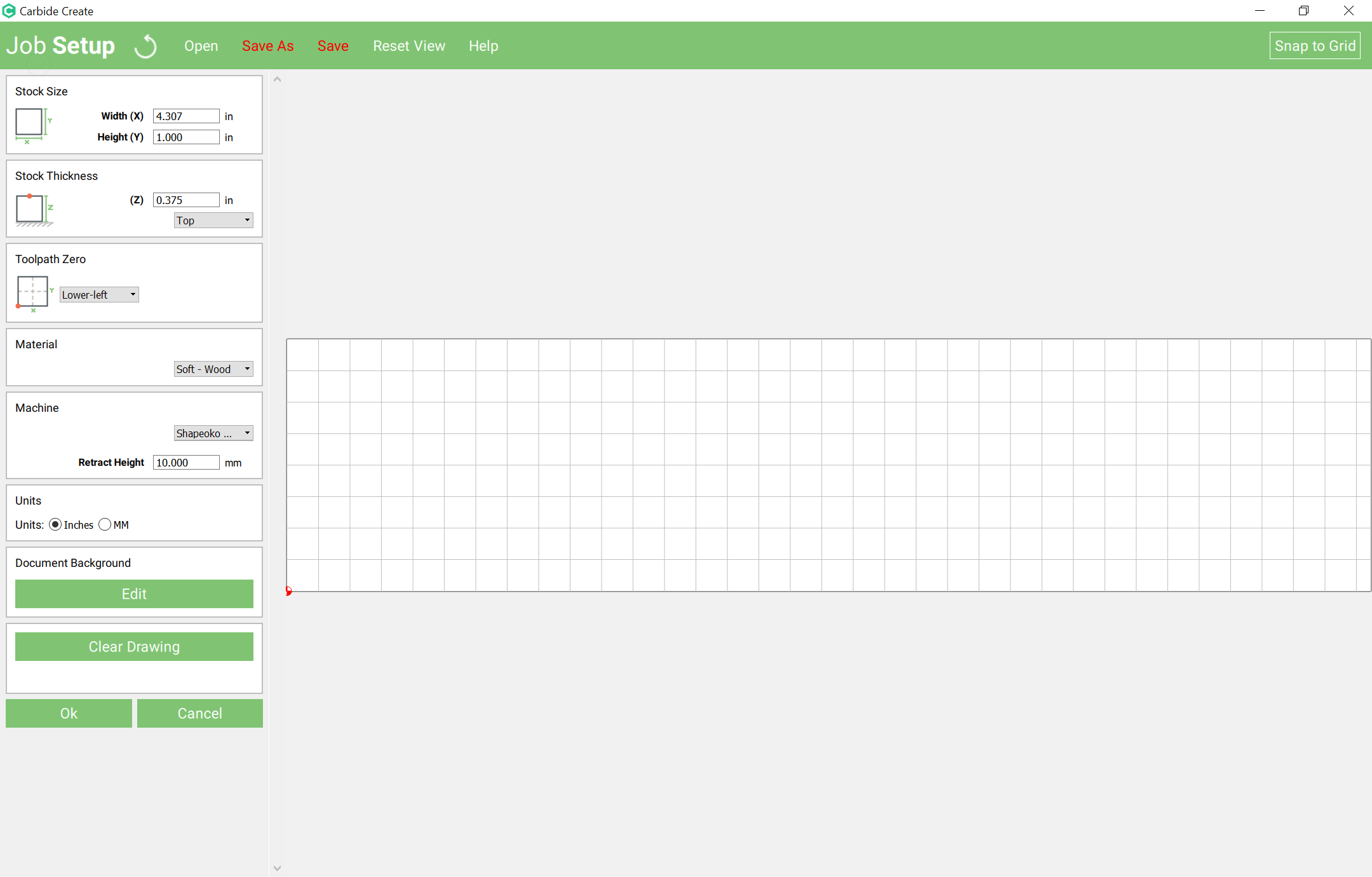
First is cutting the stock to size — how to approach this is dependent on whether one is using sheet goods or an oversize board (in which one would do a profile cut around all four sides) or a board which is the correct size (in which case one would mill a fixture to hold the stock in place and just make cuts (with manually added tabs) at the ends.
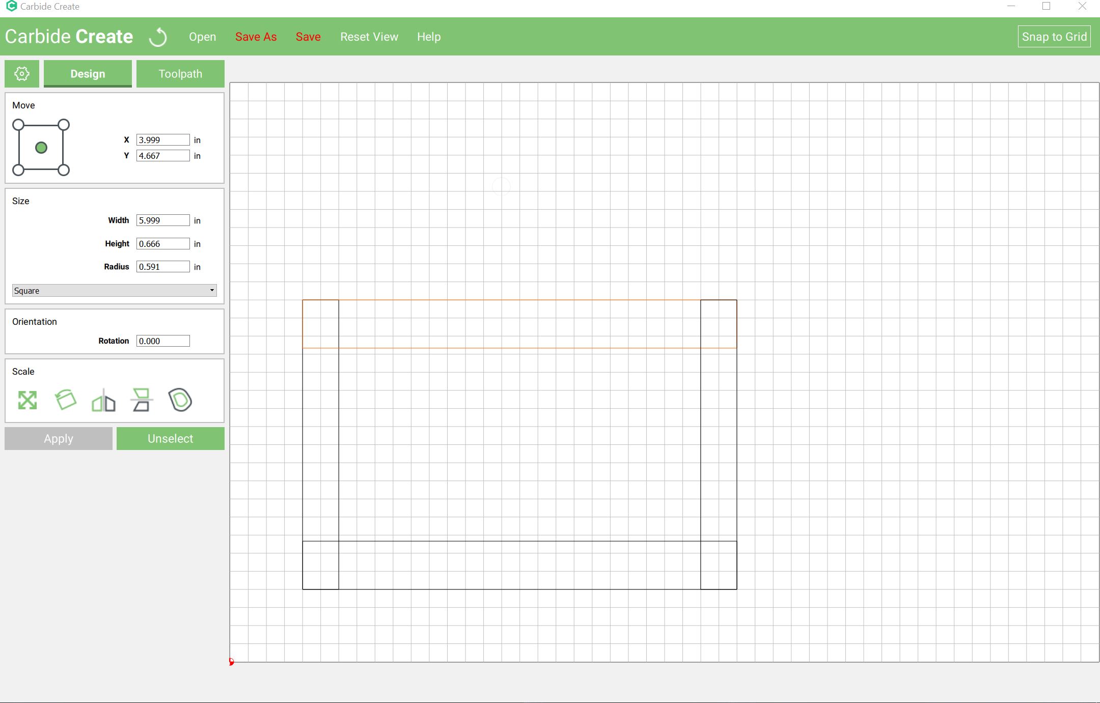
Since the former is easy, we’ll focus on the latter. With a box height of 4" we need a pair of rectangles each as tall as the box height, the first as wide as the length, the second as wide as the width, and spaced appropriately.
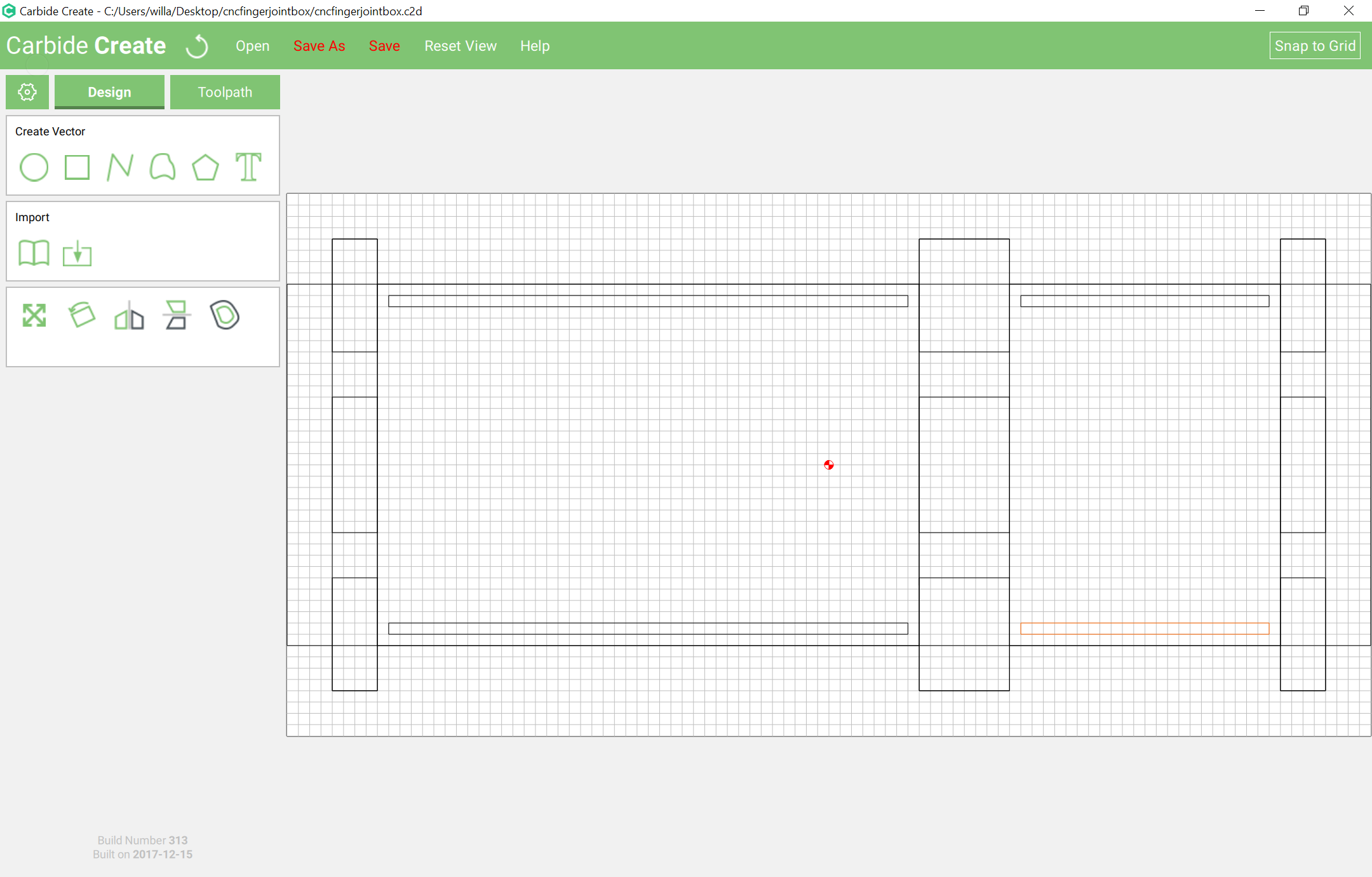
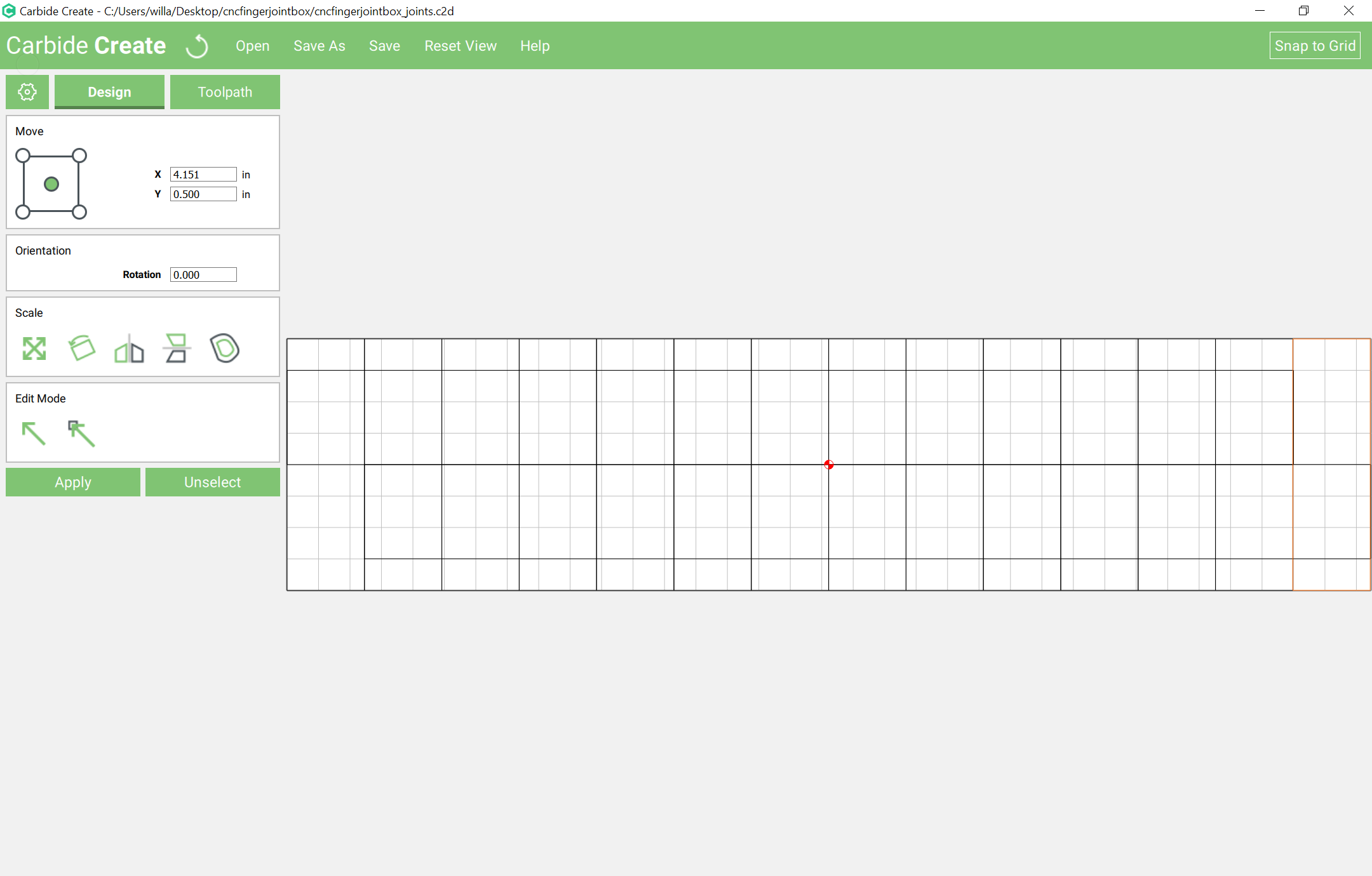
Using Carbide Create the easiest way to do that is to draw rectangles, scale each to the width or length and then arrange them to form the rectangle:
Create a new file which has a stock size which is box height plus pin height (where pin height == box height / number of pins) wide and is thickness * 2 + diameter or more in height (we’ll use diameter *2):
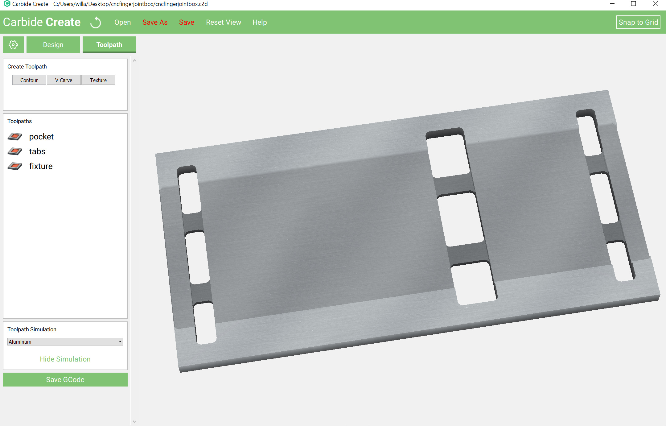
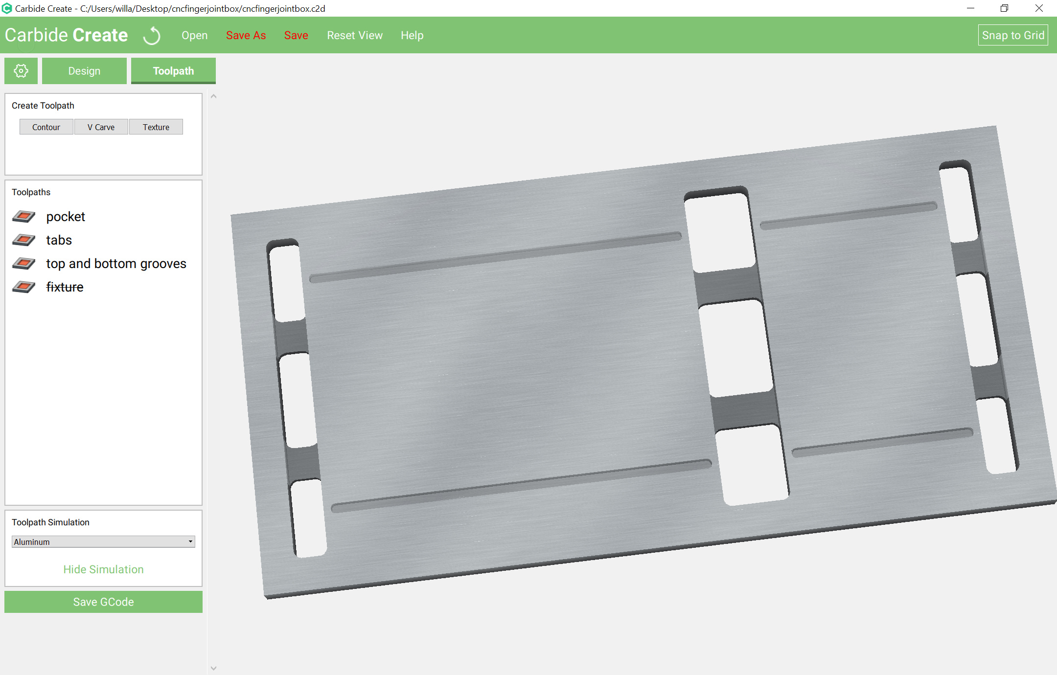
Mill a fixture which will hold the two boards spaced by pin height at a right angle at the front of the machine.
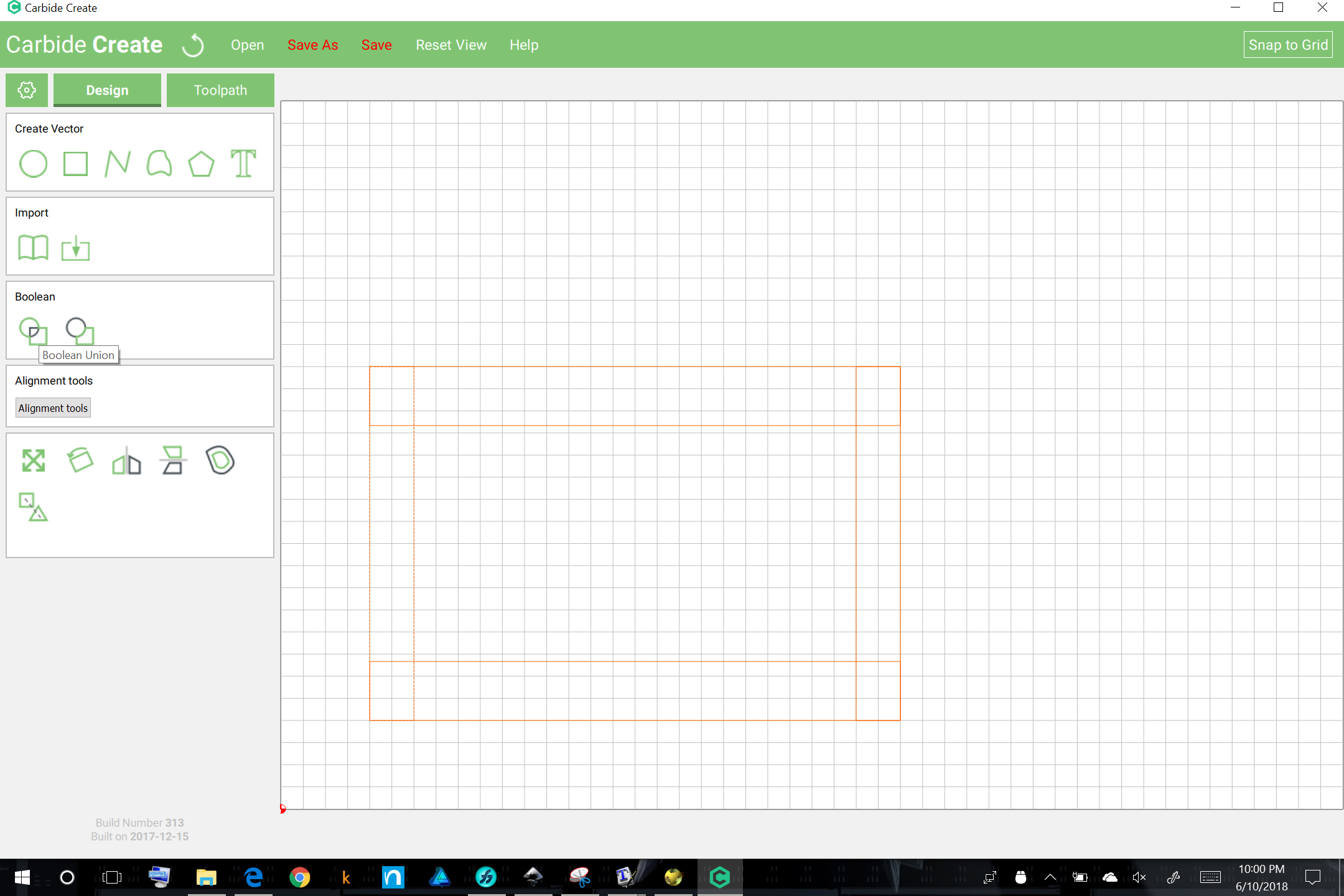
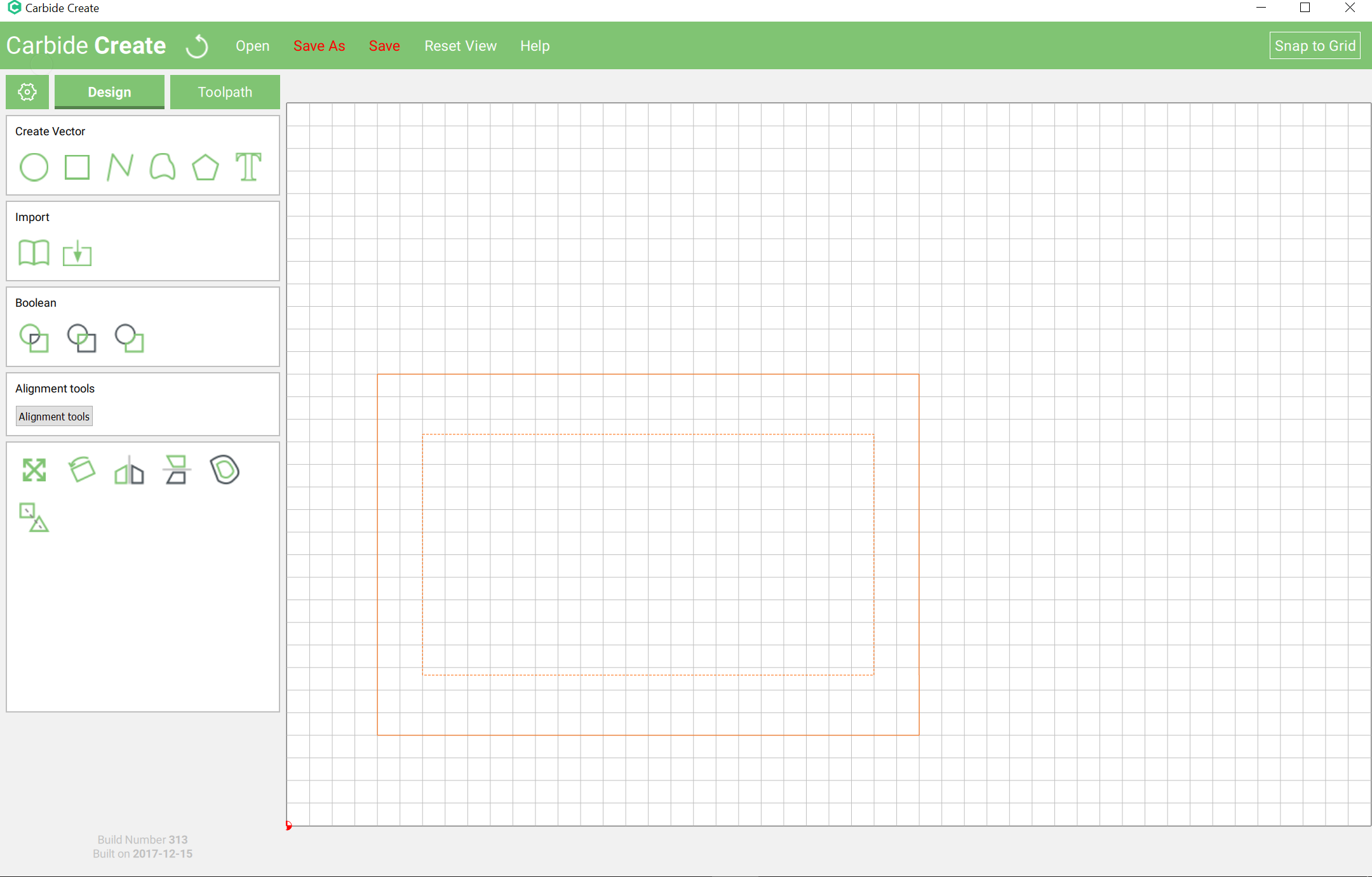
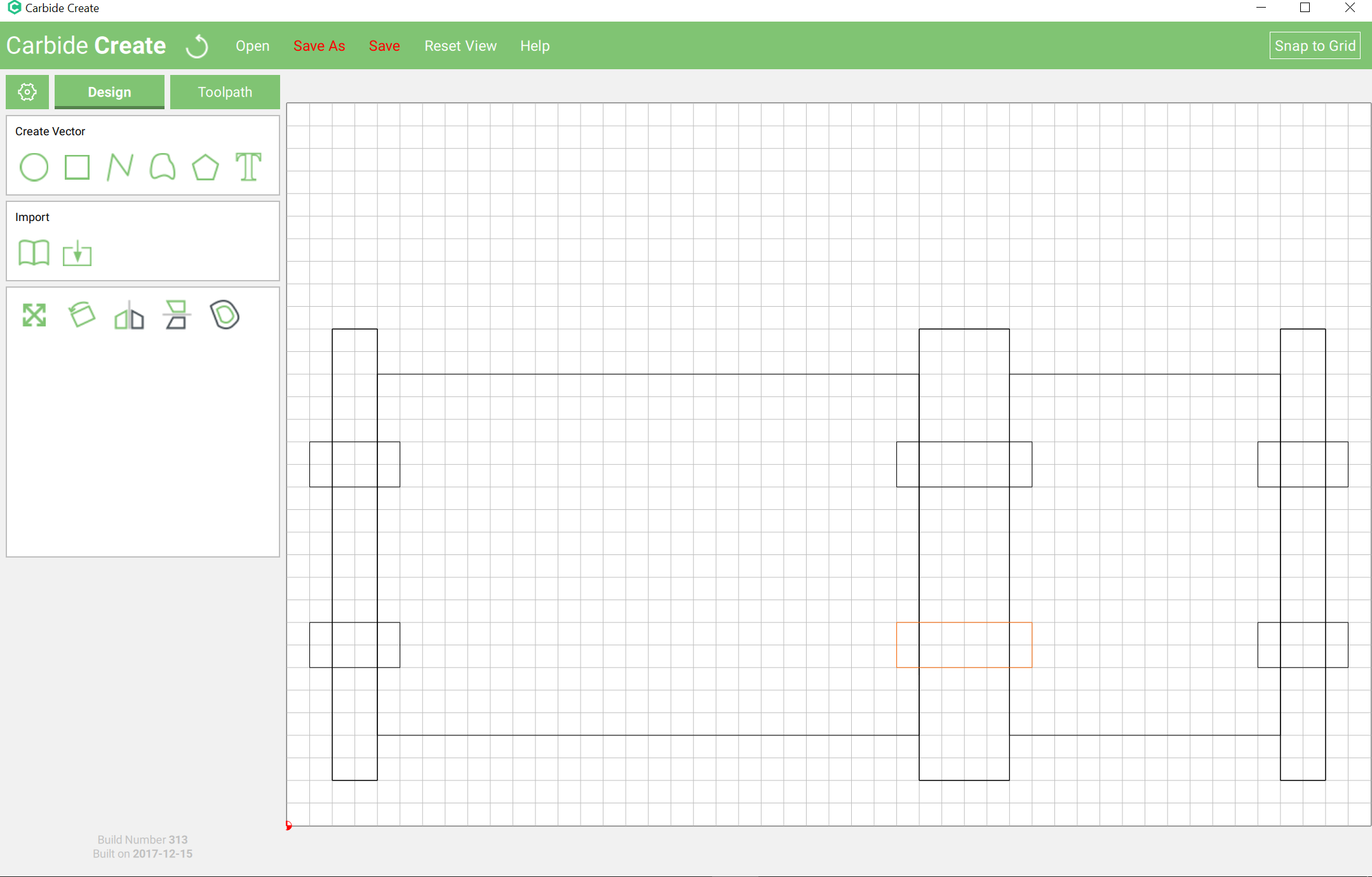
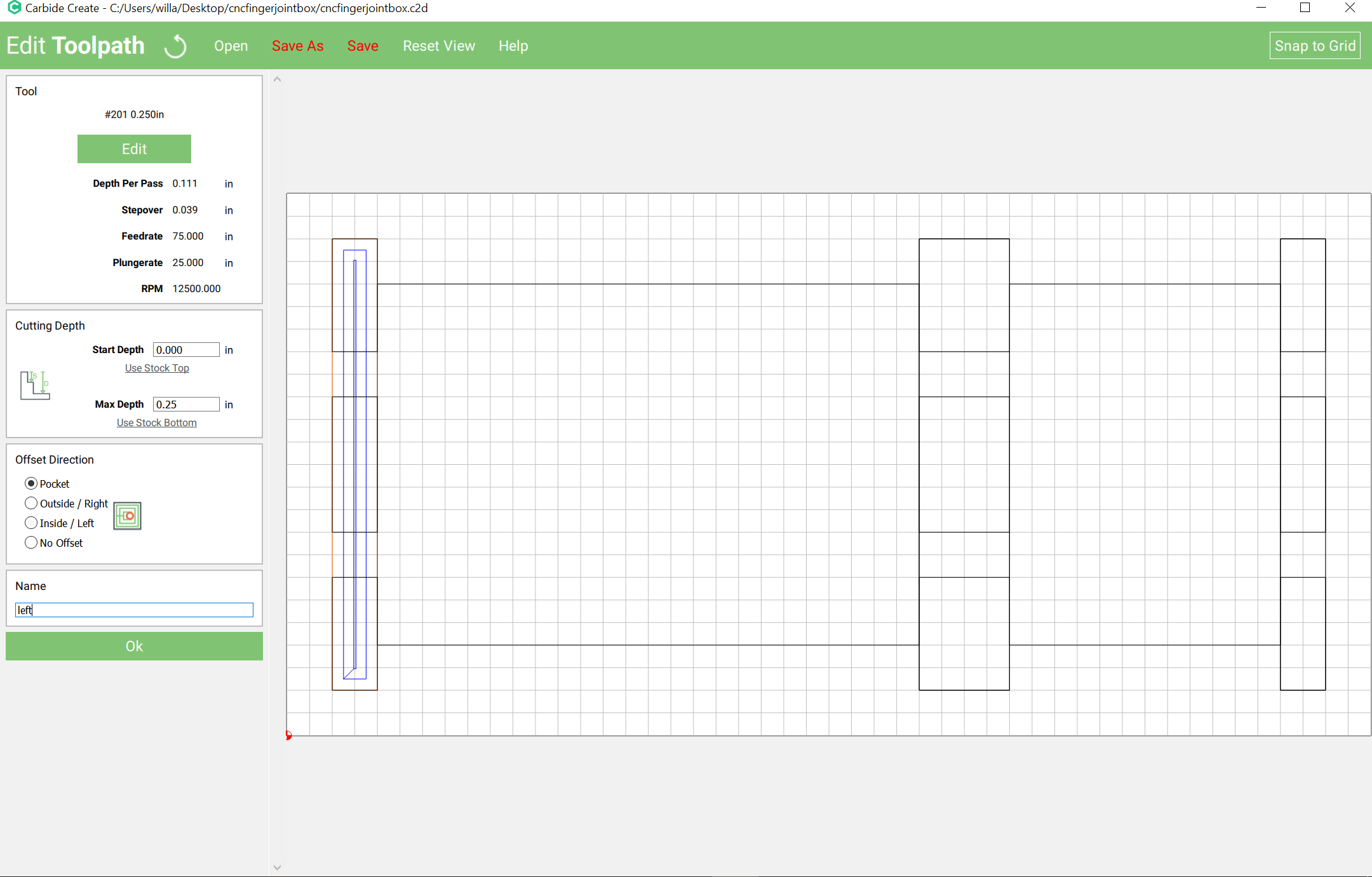
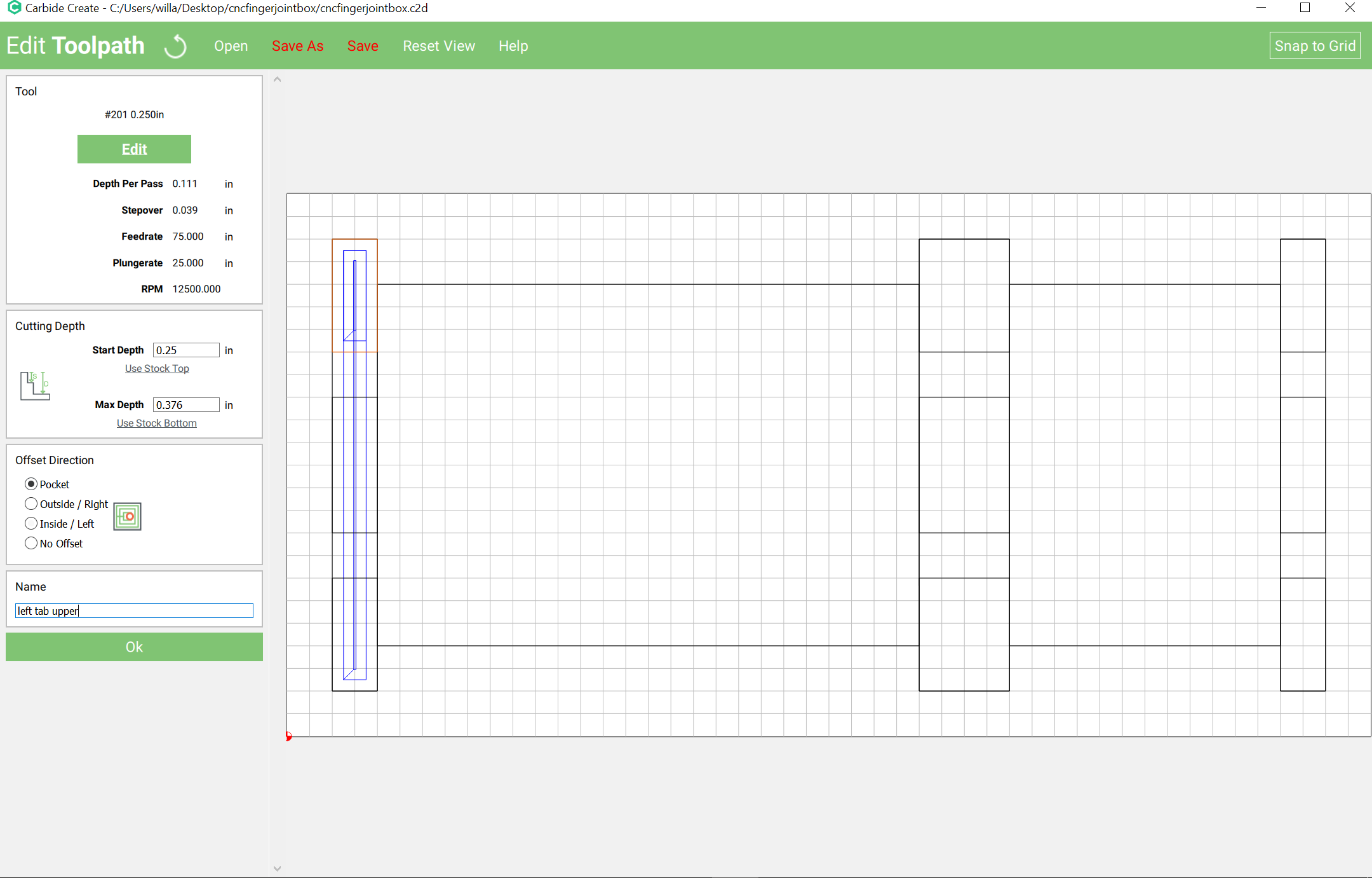
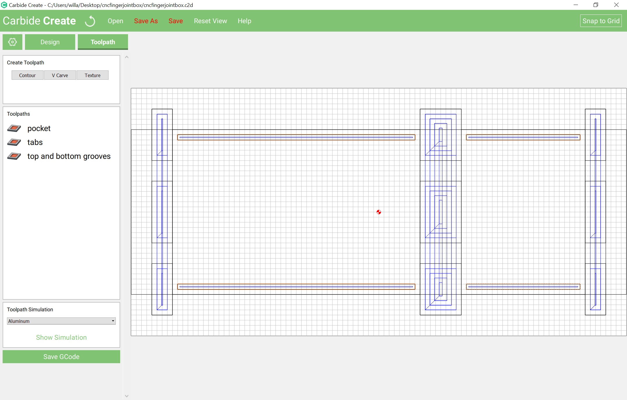
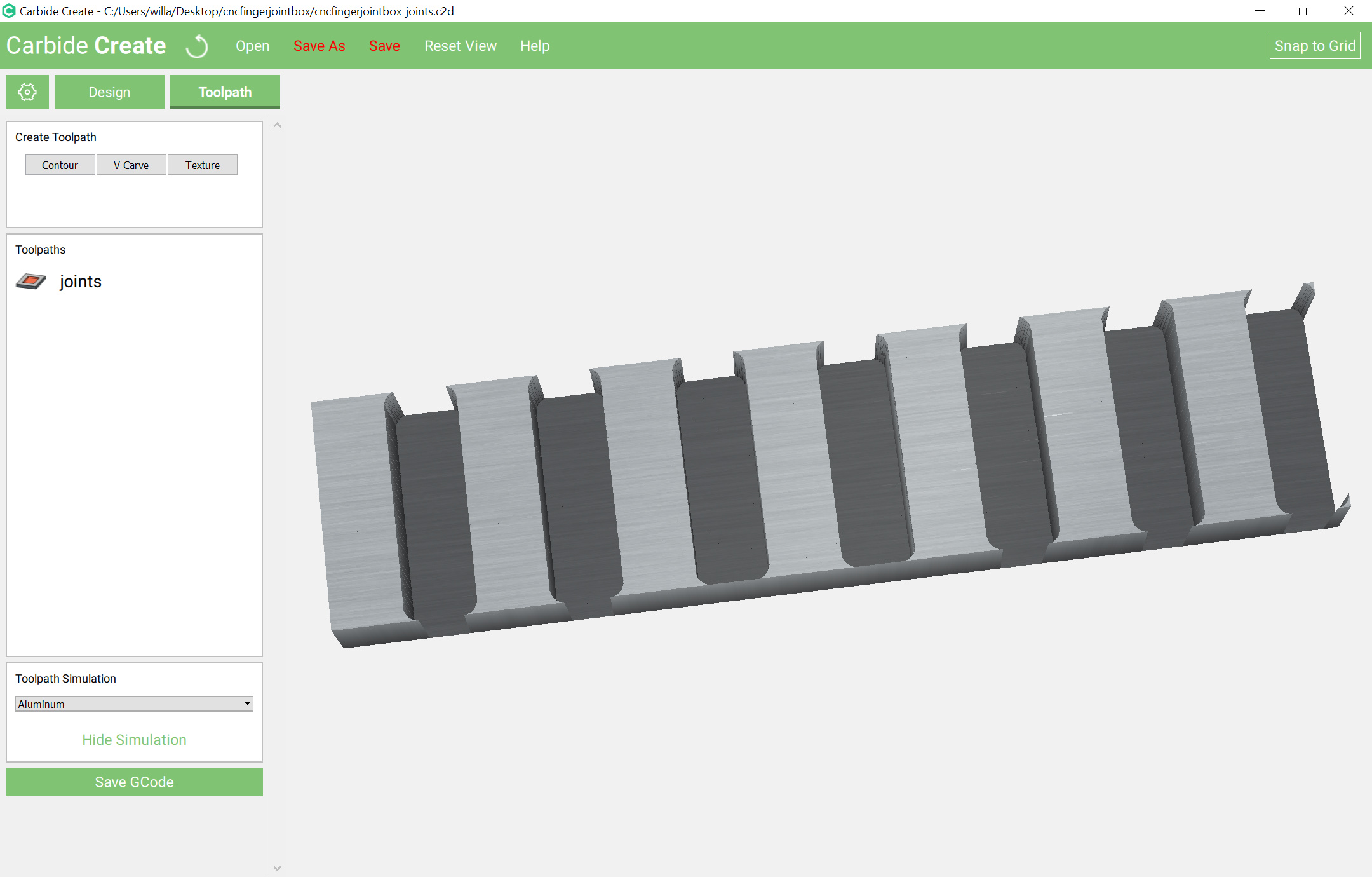
Then cut a series of rectangles which are as tall as the stock and pin height wide spaced out by pin height — the easiest way to do that in Carbide Create is to draw # of pins +1 adjacent rectangles which are appreciably taller than the stock height, group them, then scale them to box height + pin height:
It will also be necessary to cut a top and bottom out of a suitable sheet thickness material at a size to fit into the grooves. This is left as an exercise for the reader.
Is The box joint program ready to Download and run.
I see here there are 2 places to download 1 at 84.0KB and 1 at 31.9KB
Do we need all of the screens shots to understand how to make it work.
Or will there be a video on how to do it.
Jeff
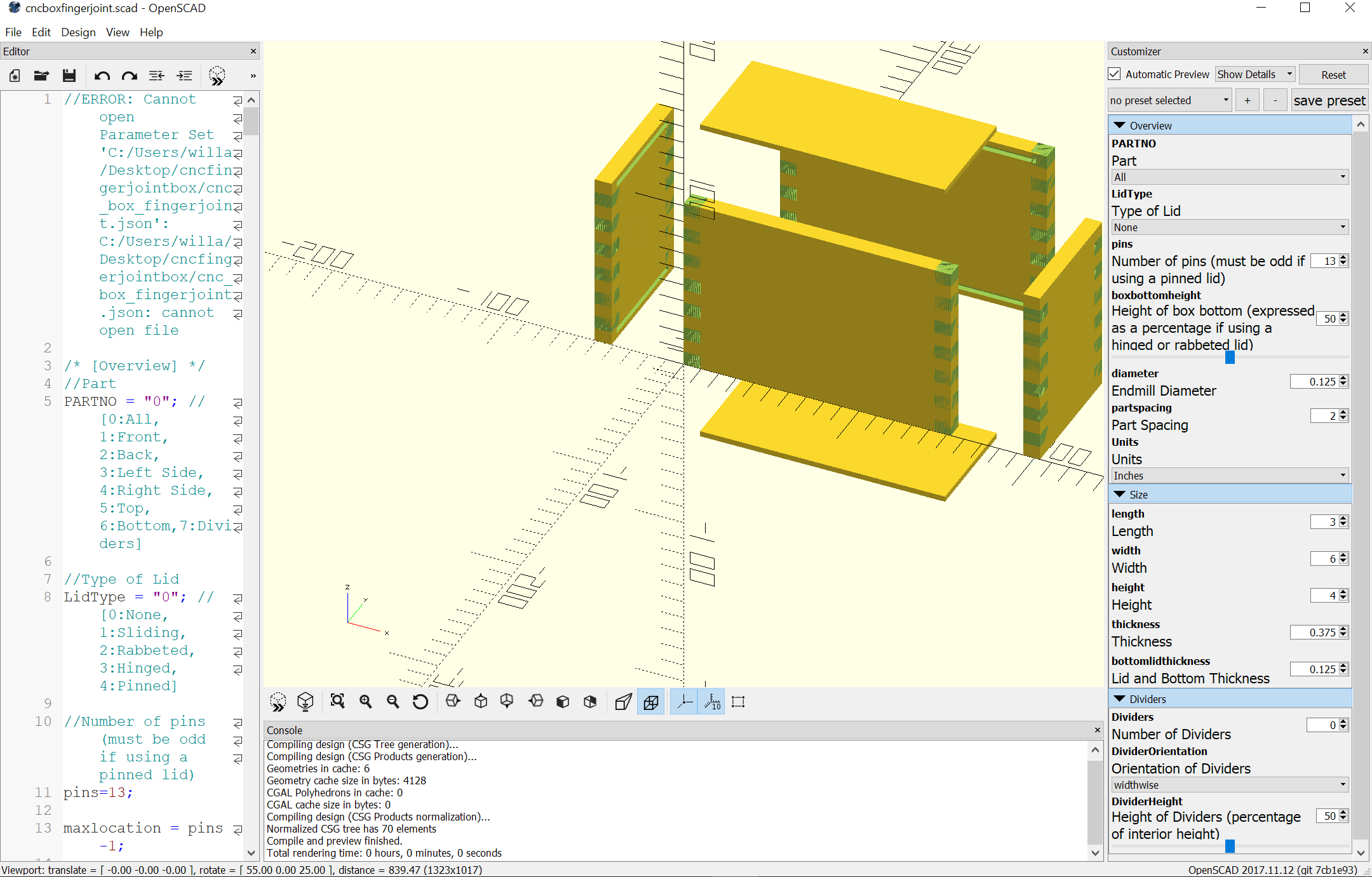
The OpenSCAD file is the interface — download it and run it to select options and get a 3D view of the box.
The .C2D file is a manually created sample box.
I don’t have the lualatex/metapost file ready yet, and I suspect folks would find it troublesome to run — at this point it’s more of a proof of concept — I’m investigating other options and will hopefully have something workable presently.
If there’s a particular size box you’d like to see, let me know and I’ll post the SVG for it.
Will the boxes I want to make are 9.5" wide 7.25 “high 3.5” deep
After downloading the 2 files I will need to reference the screens that you have posted here Right?
Thanks Jeff
I guess I am a little confused, as to where you stand with the program.
I can not find The OpenSCAD file is the interface — download it and run it to select options and get a 3D view of the box. Will there be a program that you will input the height width and depth and thickness and size of pins and the program will do the rest. Then you will choose the cutter to use for the tool paths
Jeff
d/l and install a recent version of OpenSCAD which has the customizer enabled
Edit | Features — check “customizer” to Enable Customizer
View | Show Customizer
Then you’d need to generate and export each part as an STL and work out cutting it if you wanted to just use OpenSCAD and the 3D model — I’ll generate an SVG as quickly as I can.
Will, when you are done with the dado /box/finger joint program it all going to be part of CC or will we need another program to set up sizes and then create a file and import into CC to create the tool paths with.
Jeff