Thanks! Glad you’ve got something which works for you — I need to work up something which doesn’t depend on commercial software — pretty much there, just need to find time to update the file to handle all four boards at once.
Well I have the program but not sure how to use it yet.
I was trying to find somewhere that the was a video that showed the joints being cut out in front of cnc .
I hope you find time soon, I have something I want to produce to sell that is going to have finger joints on all 4 edges and a dado for a back and a dado for a thin piece of plexiglass
Thanks Jeff
I show a board clamped to the front of the machine at:
Currently trying to finish up the design for the fixture — need to work up a pair of parts which can thread up/down the rod and provides a threaded connector at a right angle — been looking through image searches, but not quite finding exactly what I want, so will probably have to either design something, or work up a design which uses an off-cut from the board.
Hey Will: How about your original design lid with an extra piece added. Some design, maybe a dragon, that can be either glued, doweled, or screwed to the lid - to be used to just lift the lid up.
That’s a great idea! I’ll see what we can do to add a lid/knob. Thanks!
Okay, here’s the first part of the fixture — cut two of them, the top three holes are used to mount it to T-track (or adjust the spacing to match threaded holes/inserts)
The lower holes have a hex cap nut epoxied into the top, and 1/4"-20 threaded rod installed from the bottom — then cut a pair of boards w/ holes drilled in them which match the spacing of the two fixture boards, slide them onto the rods and use wing nuts to position them to match the board lengths.
There should also be 4 small pieces which have a vertical hole drilled through them, a pair of slots to hold a square nut, and holes drilled into either end which line up with the nuts — use plastic bolts to hold them in place on the threaded rod from one side, and adjust a bolt in the other to hold the boards vertically, with two offset by half the board thickness.
cncfingerjointbox_fixture_main.c2d (22.1 KB)
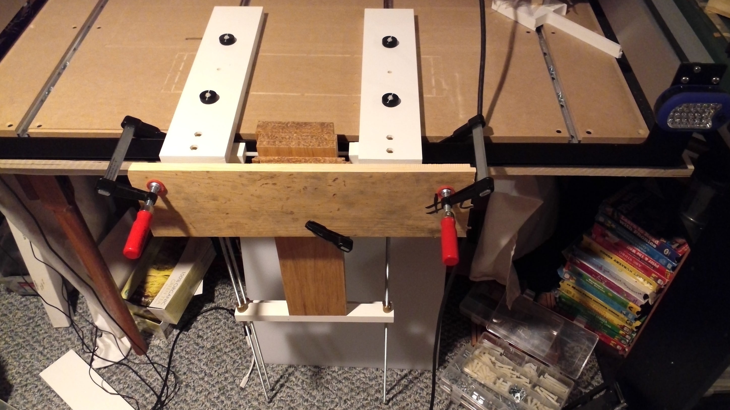
Managed to get two sets of parts cut:
Which shows more or less how it ought to work.
Not included in the photo are three additional boards (all four would be cut at the same time) and a front cross bar which the two F-clamps would hold in place to clamp the four boards, and a set of adjustable clamps which would hold the boards from side-to-side (still need to cut those, but not convinced of the design yet).
The brass nuts are speed nuts from:
https://www.garrettwade.com/frame-clamp.html
and ideally I’d have a bunch more of them.
A nicer version is available from:
http://www.leevalley.com/us/wood/page.aspx?p=31162&cat=1,43293
(but of course, I just missed free shipping, story of my life)
cncfingerjointbox_fixture_secondary.c2d (14.7 KB)
1 Like
And finished the first of the four adjustable clamps:
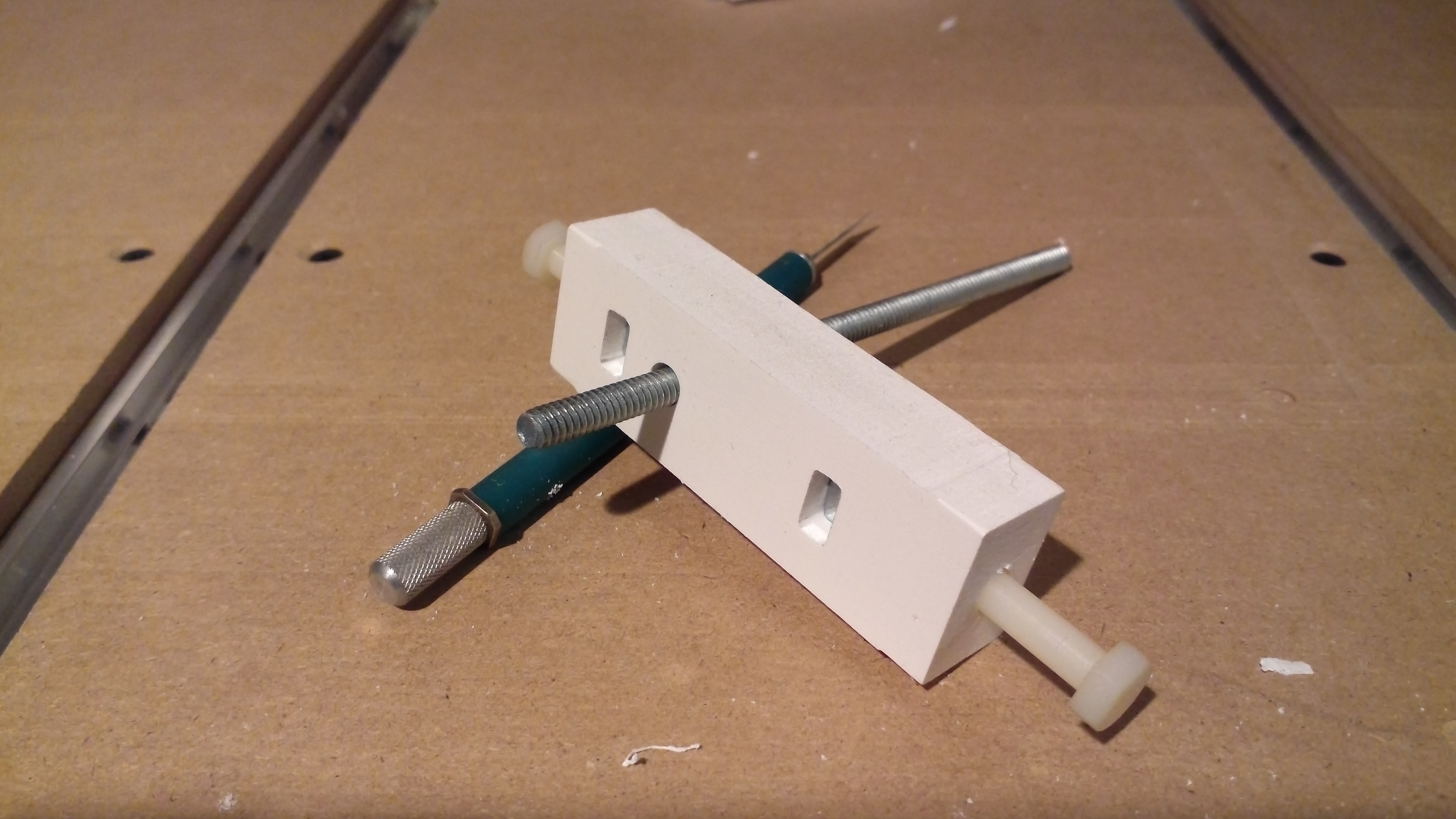
(The X-Acto knife has a razor saw blade which I’ve found very useful for cutting tabs)
Here’s a Carbide Create file to cut one, along with a fixture to hold a 1/4"-20 square nut to use to drill the holes in the ends for the nylon bolts (each mates up with a square nut, one holds the fixture in place on the threaded rod, the other allows one to adjust for placement of the boards.
cncfingerjointbox_fixture_3_sideclamp.c2d (15.2 KB)
Everything goes together to look something like:
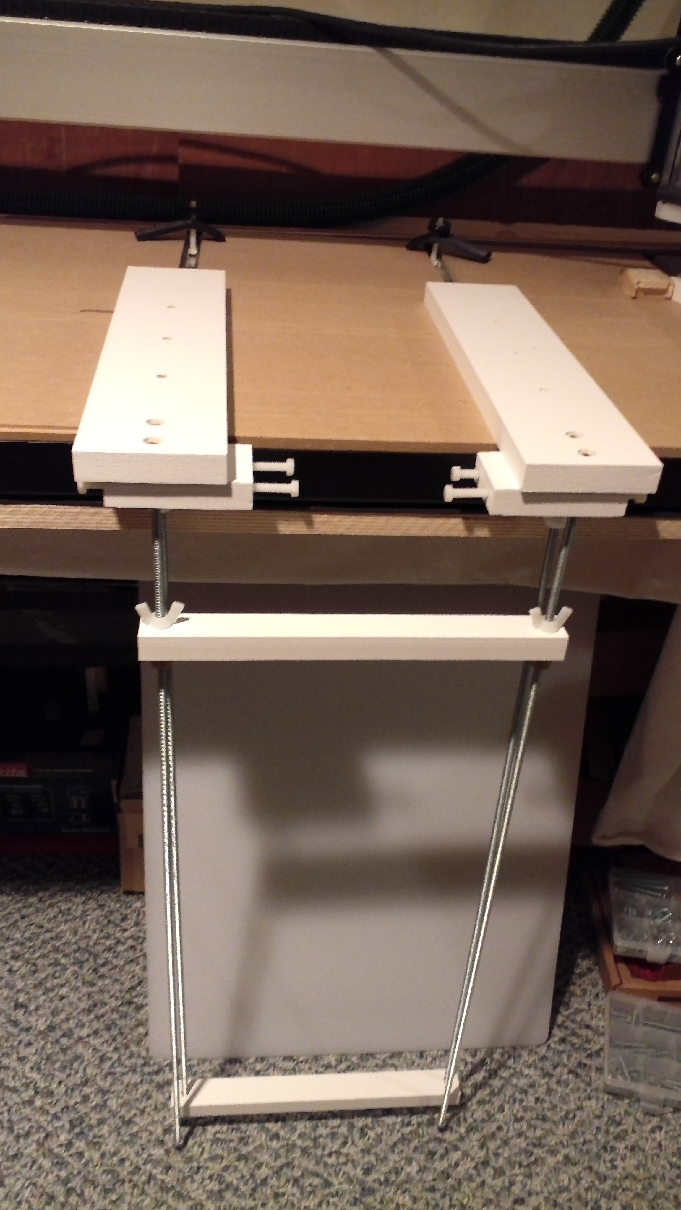
I will note that using wingnuts is very tedious, so placing an order for more speed nuts now.
Hopefully this weekend I can find time to cut some boards to length and then put the fixture to use.
Is the program done, ready to set up the cut files.
Jeff
Please download and try the OpenSCAD file above — set up a particular size / style of box and I’ll run out some files for it.
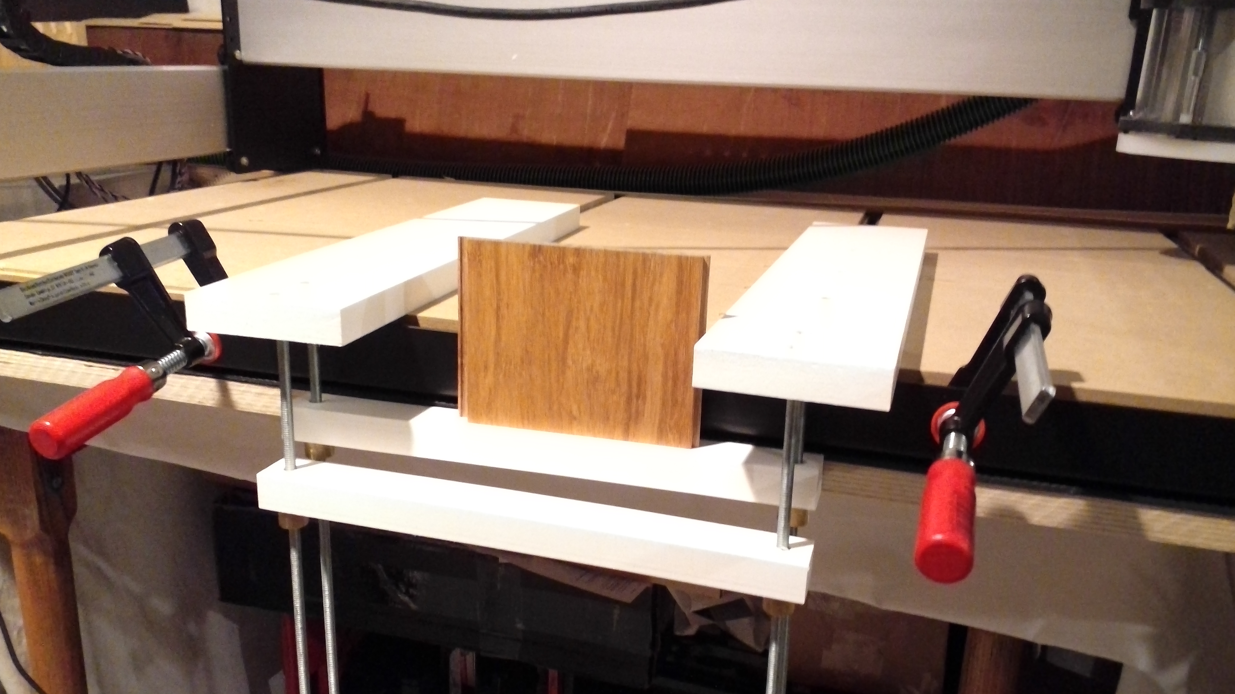
Neat thing about using flooring as lumber — you can clamp along the sides even when cutting almost up to the edge:

1 Like
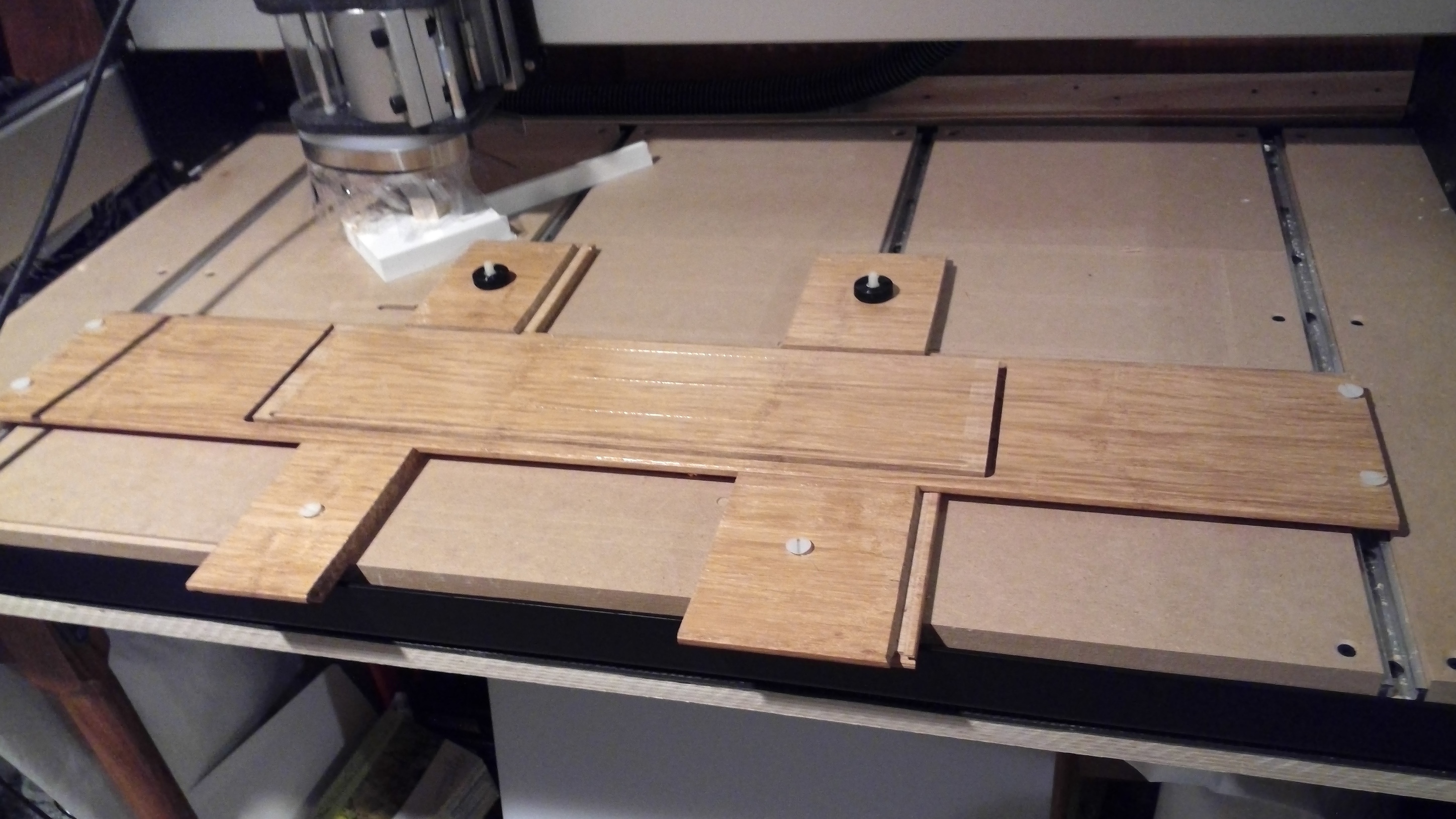
And two more have been cut, plus some scrap.
Made some notes on cutting bamboo at: https://wiki.shapeoko.com/index.php/Materials#Carbide_3D_.28Bamboo.29 — finding I’m needing more RPMs and slower feed than I’d expected — hoping that adjusting the paths a bit and leaving a roughing clearance and making a finishing pass to size will sort this out.
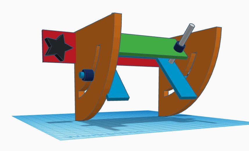
OK I have had this in my head for a few days now so I thought I would sketch it out. It could be milled out of aluminum right on our machines. You would have to carefully drill and tap a pair of holes on the front of the Shapeoko. It is adjustable so you could cut at angels other than 90*. I just did this in Tinkercad in about 45 minutes so it’s just a little rough right now.


1 Like
Very cool design! I actually considered something similar, but decided to forego the angular adjustment — my idea was to have grooves cut with a V bit as you’d see in a Hirth coupling to align it at 1 degree increments, so it needed a two-sided operation.
Arguably you’d only need 5 degree increments — 15 for Tailmaker, 45 for 4 sided boxes — but I suppose if folks want to do other style of boxes or bowl blanks you’d want to facilitate those.
Here’s a sobering post on the consequences of a 1 degree error compounded 16 times: https://www.reddit.com/r/woodworking/comments/9k1z2l/1_degree_error_compounded_16_times/

Can’t wait to see the parts after they are cut.
I meant no disrespect to what you are designing. I just got excited when watching this guy on YouTube doing crazy finger joints on a CNC.
1 Like
None taken, I’m mostly a very prosaic person, w/ a minimalist design aesthetic which was usually criticized as being too austere in college critiques.
It is really ingenious some of the joints folks have worked up — the really interesting thing is how old some of them are such as Knapp joints (which dates back to just after the American Civil War).
1 Like