Thanks! And right, the cutrocket upload!
I think I also missed the edit made by @Sherpa even though I put a like on the post. Maybe the admins can change that notification behavior?
Thanks! And right, the cutrocket upload!
I think I also missed the edit made by @Sherpa even though I put a like on the post. Maybe the admins can change that notification behavior?
True, but then I would have to add LED in the first place. Currently all the light comes from the luminescent color in the epoxy: no need for a power source.
Well, how’s that working with Mario? Just sayin’. ![]()
I can see that the edges of the acrylic are lit by the epoxy. Maybe sanding the Mario area pretty rough will make him catch some light?
Probably I’ll just try, but that will introduce some intensive re-sanding if it doesn’t work. 
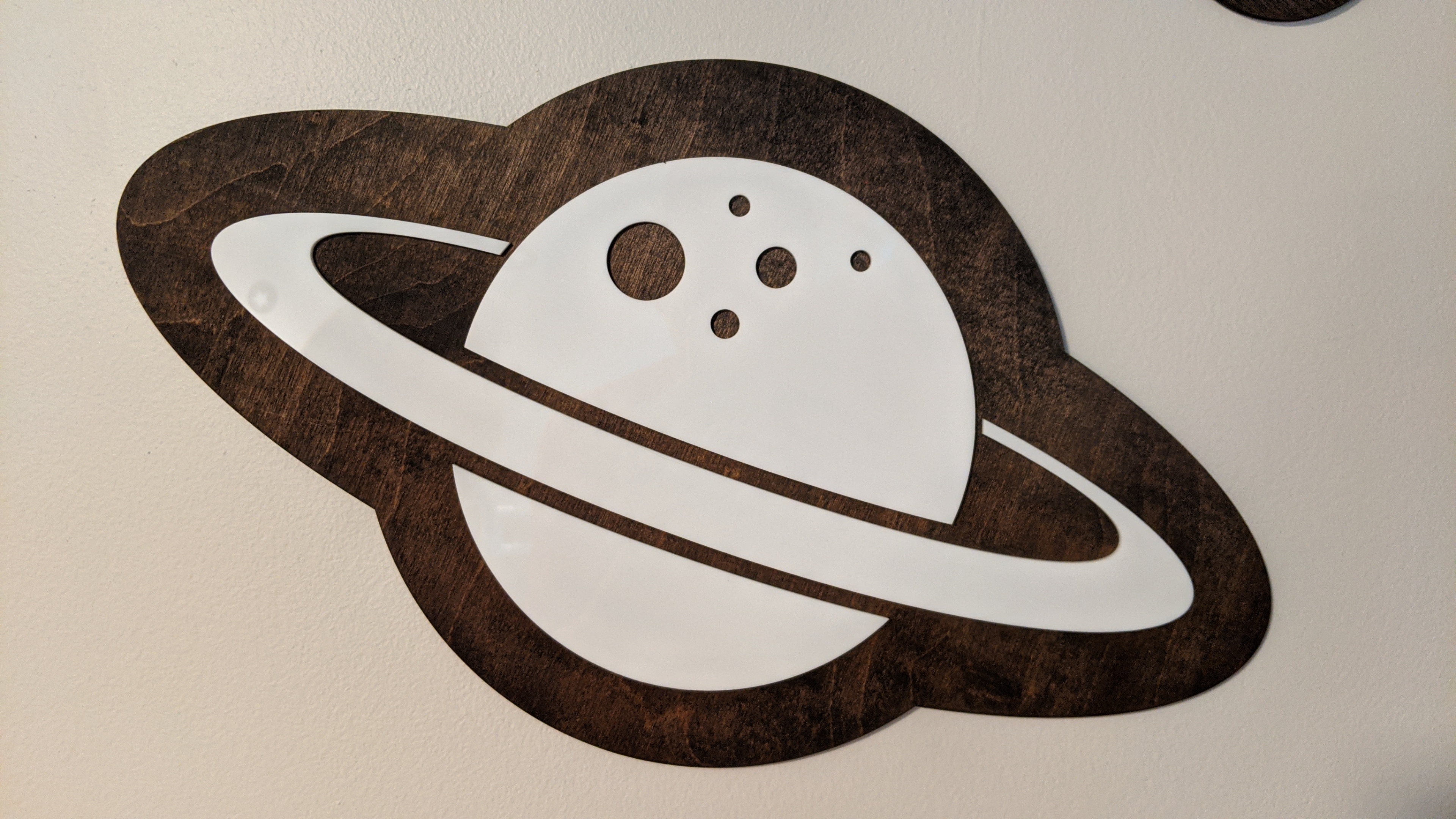
Entry #1 (Henry’s Space Room)
The plastics contest hit at the perfect time for me as I was planning and working on several pieces that utilize the cutting of plastic. Long story short(er), we had our 3rd child at the end of March (crazy time to bring a baby into the world), and probably like many parents of two preschoolers, we didn’t prepare as much as we should have. Then quarantine happened and my wife decided that we would empty our “office” and move the 3yr old in there, so the baby could eventually move into the “baby room”. He got to choose what kind of room he wanted and he said “I want a Space Room”. My thoughts immediately went toward making a “control panel”, but that will be for another day (if I get the permission). My wife wanted a “less flashy” style for the room…she likes Pottery Barn and Crate and Barrel type stuff. Anyway, enough of it…here’s what I came up with.
There’s a few more stars and a “shooting star” on the opposing wall. The white is all 3mm white (very slightly translucent) cast acrylic.
All designed in inkscape initially, and then moved to Fusion for the toolpaths. The wood is just ¼” birch ply from Lowe’s also cut on the SO3 (the H-E-N-R-Y letters had been done a couple years ago). Acrylic super glued to the wood.
After some testing, I settled on:
⅛” single flute upcut endmill (cheap one)
Feedrate: 3210 mm/min
Speed: DeWalt on 1
Plunge: 888 mm/min
DOC: 1mm
Screenshot of initial Inkscape design:
I had to change the Earth design later because it didn’t fit the simple theme (looked like a PITA to cut). And the rocket? Well…more to come on that.
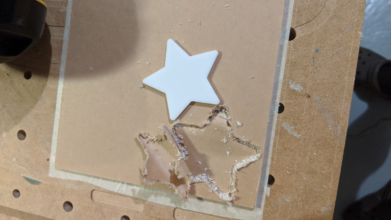
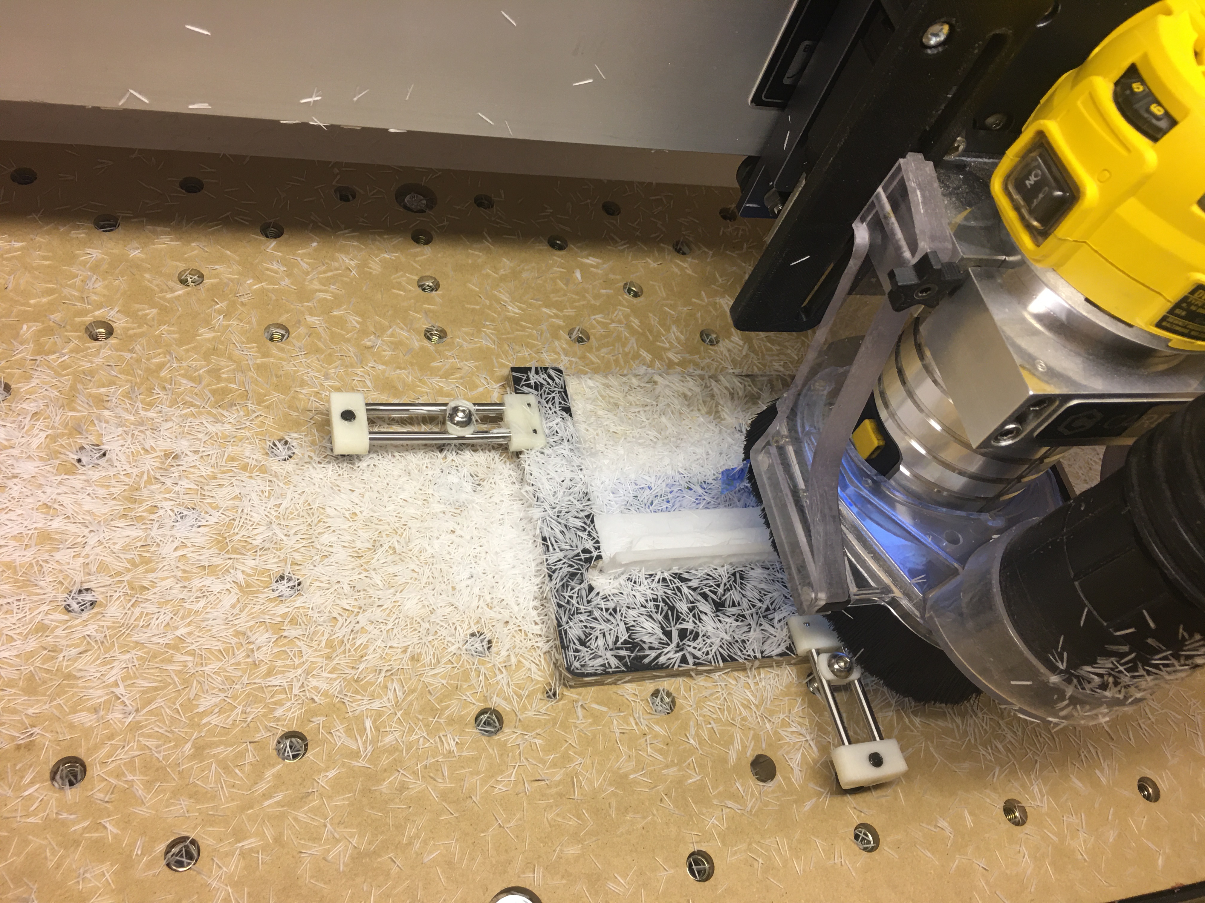
Anyone else measure success by whether or not you cut through the bottom layer of tape?
I really was surprised at how well the acrylic cut. I got to a “That’s a pretty good result” point almost right away, tried doubling the feed and got to a “That’s a faster way to get to a pretty good result” point. I didn’t need to do any post processing to the acrylic. I found that the key was to have it secured everywhere…I went through a LOT of tape and a LOT of Super glue. I’m assuming another key was that I was using cast acrylic. I had one break point that erased the Panama Canal, but it broke cleanly and now it’s part of my “simple design”.
Not knowing there would be a plastics contest, I just imported one SVG at a time into the same Fusion project. Basically used it as a template. I’ll share the Inkscape vector and the Fusion template (with toolpath). I just needed to change the sketch and update the toolpath. One could also use Carbide Create or any other CAM program.
HenryRocket.svg
SpaceRoom_Acrylic v2.zip (97.8 KB)
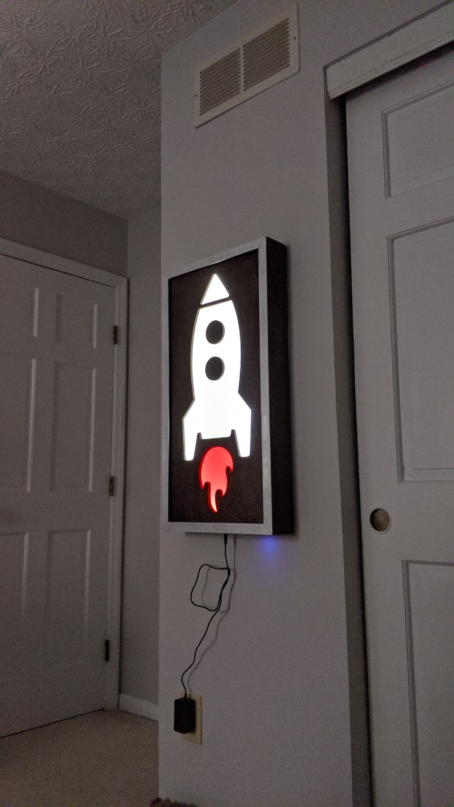
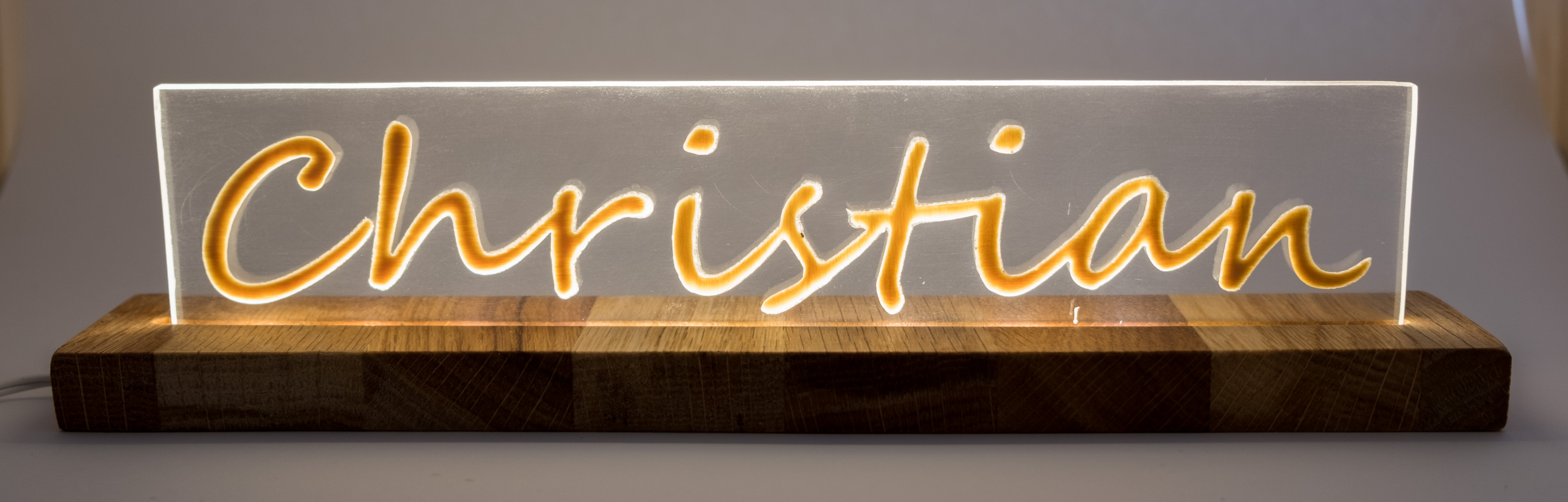
Entry #2 (Rocket Lamp)
I decided to submit this one separate because it definitely was a separate project. I wanted to make a light for the “Space Room”, and I wanted it to be the same theme with dark stained wood and white. Here we go.
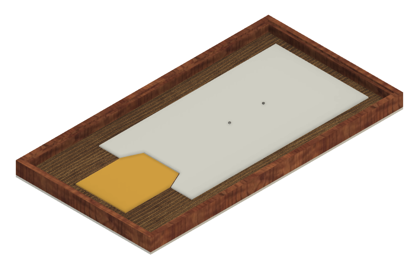
Fusion Model:
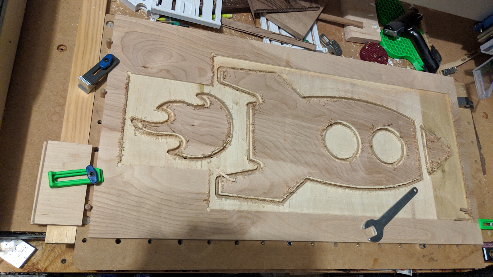
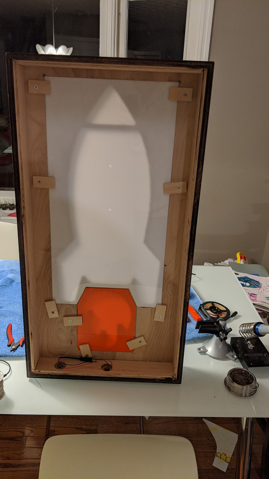
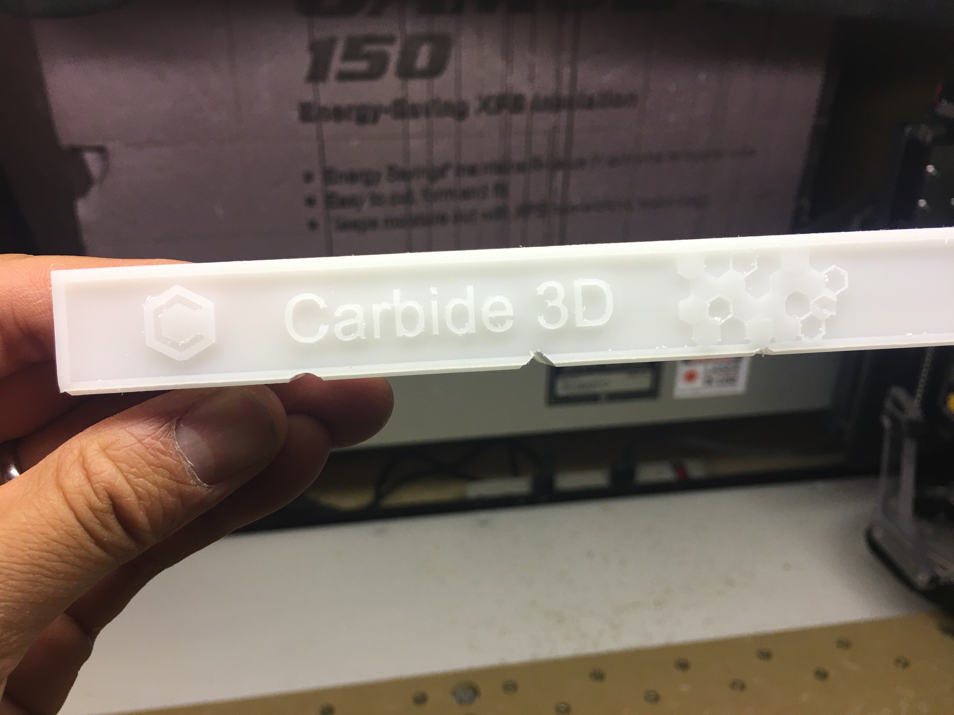
Real Deal:
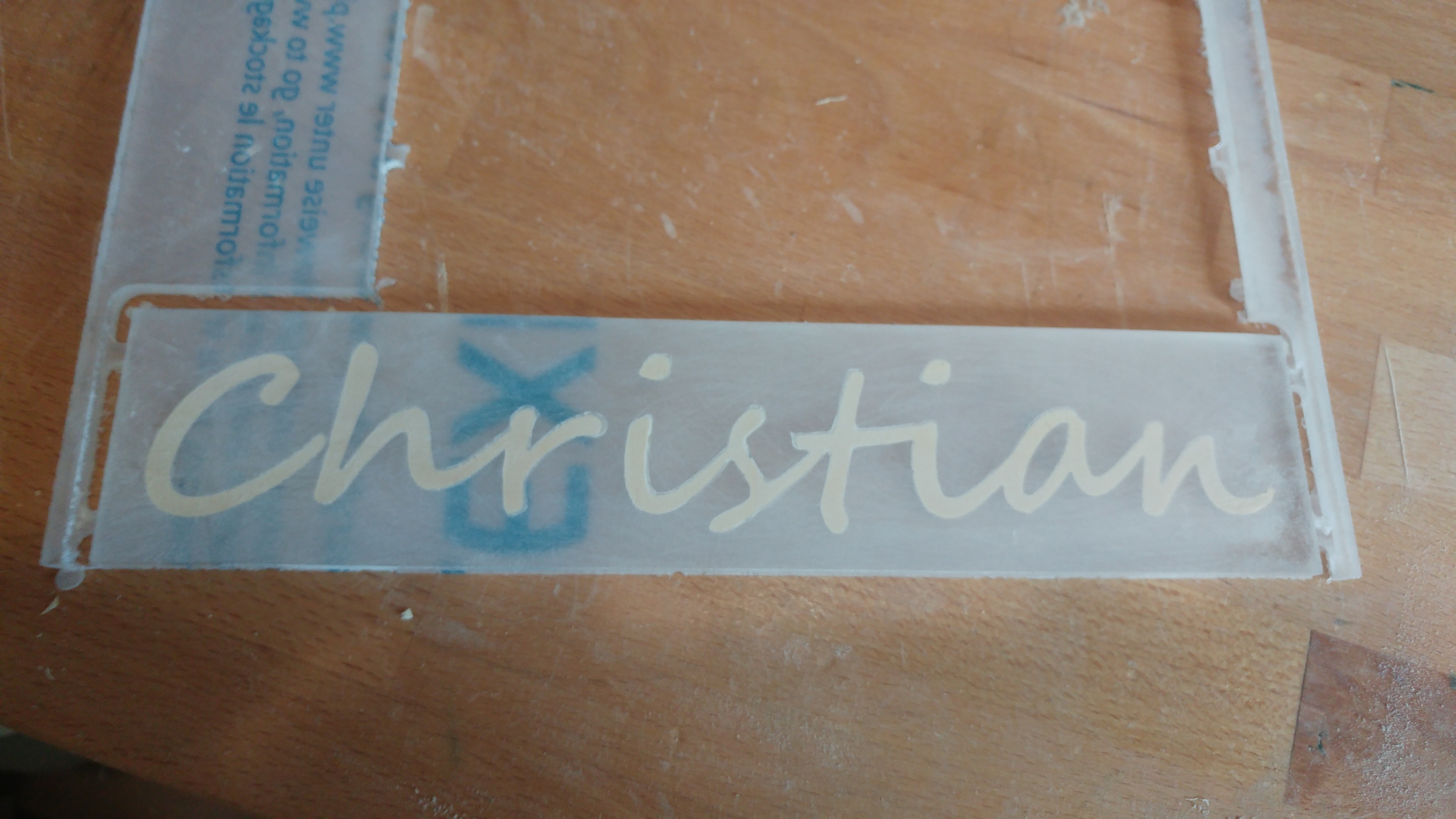
The acrylic (white and orange cast) was cut exactly as above:
⅛” single flute upcut endmill (cheap one)
Feedrate: 3210 mm/min
Speed: DeWalt on 1
Plunge: 888 mm/min
DOC: 1mm
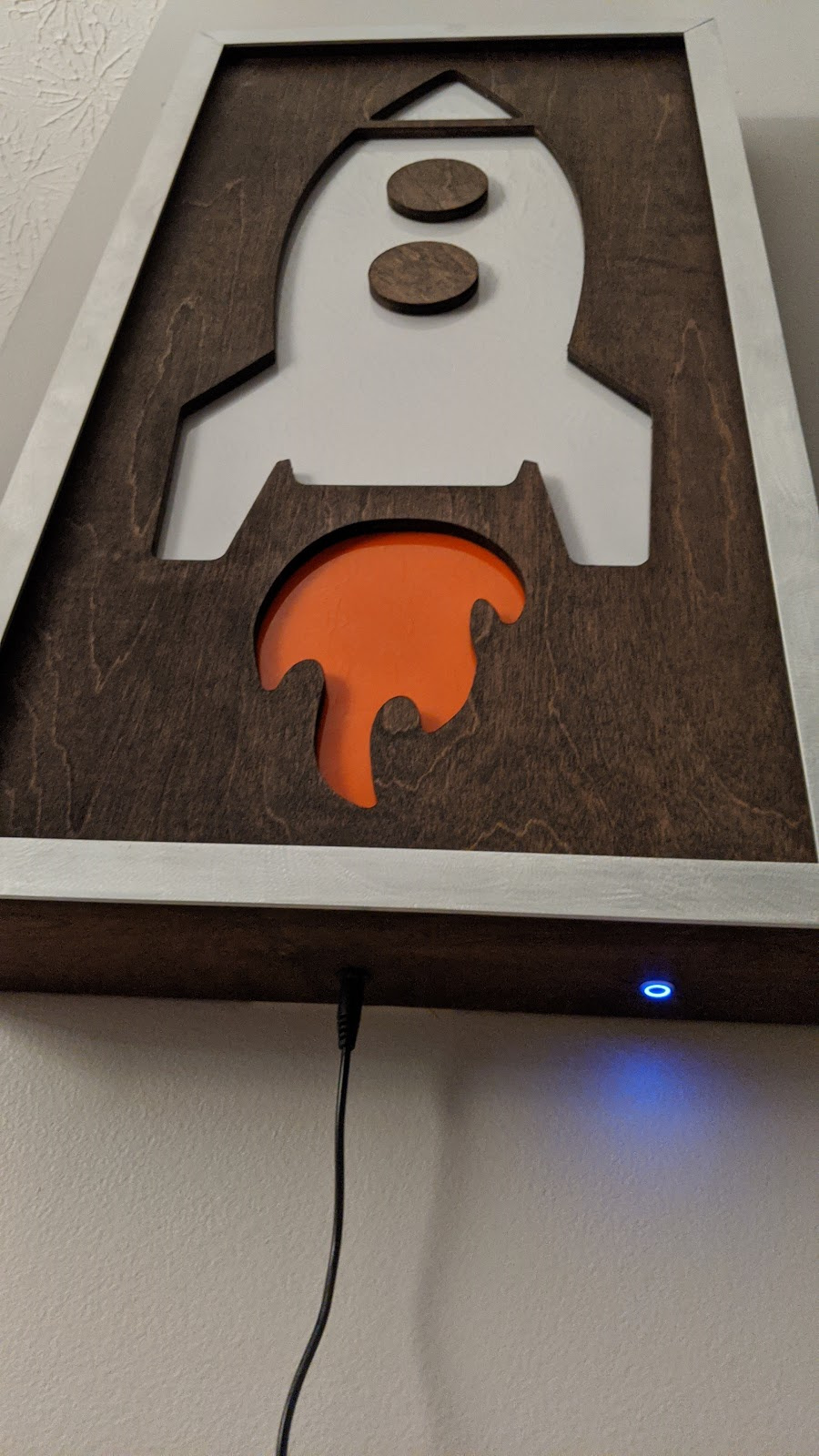
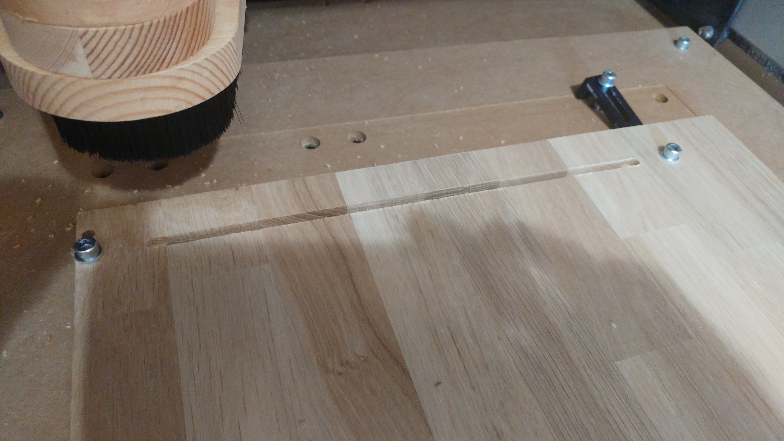
Frame was made from ¾” ply. Mitered corners with a dado groove to hold face
Face is ½” ply.
Back is ¼” ply.
Trim with mitered aluminum strips. (Sanded, but I thought HARD about trying some “engine turning”).
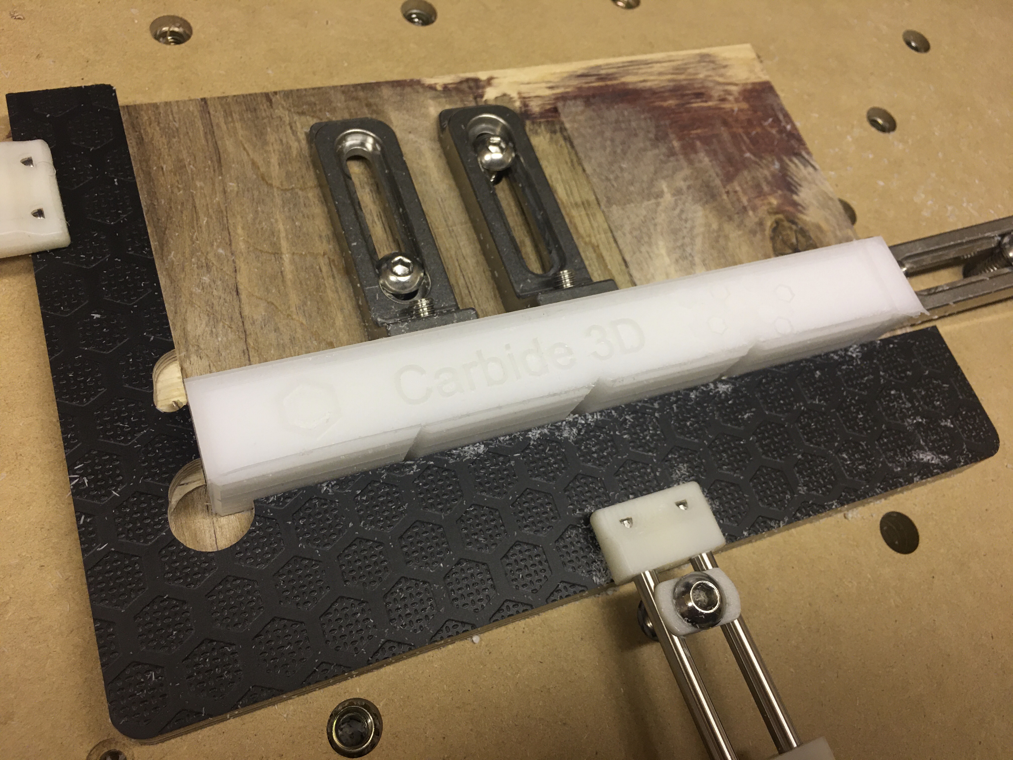
The back of the face was cut with a pocket for acrylic.
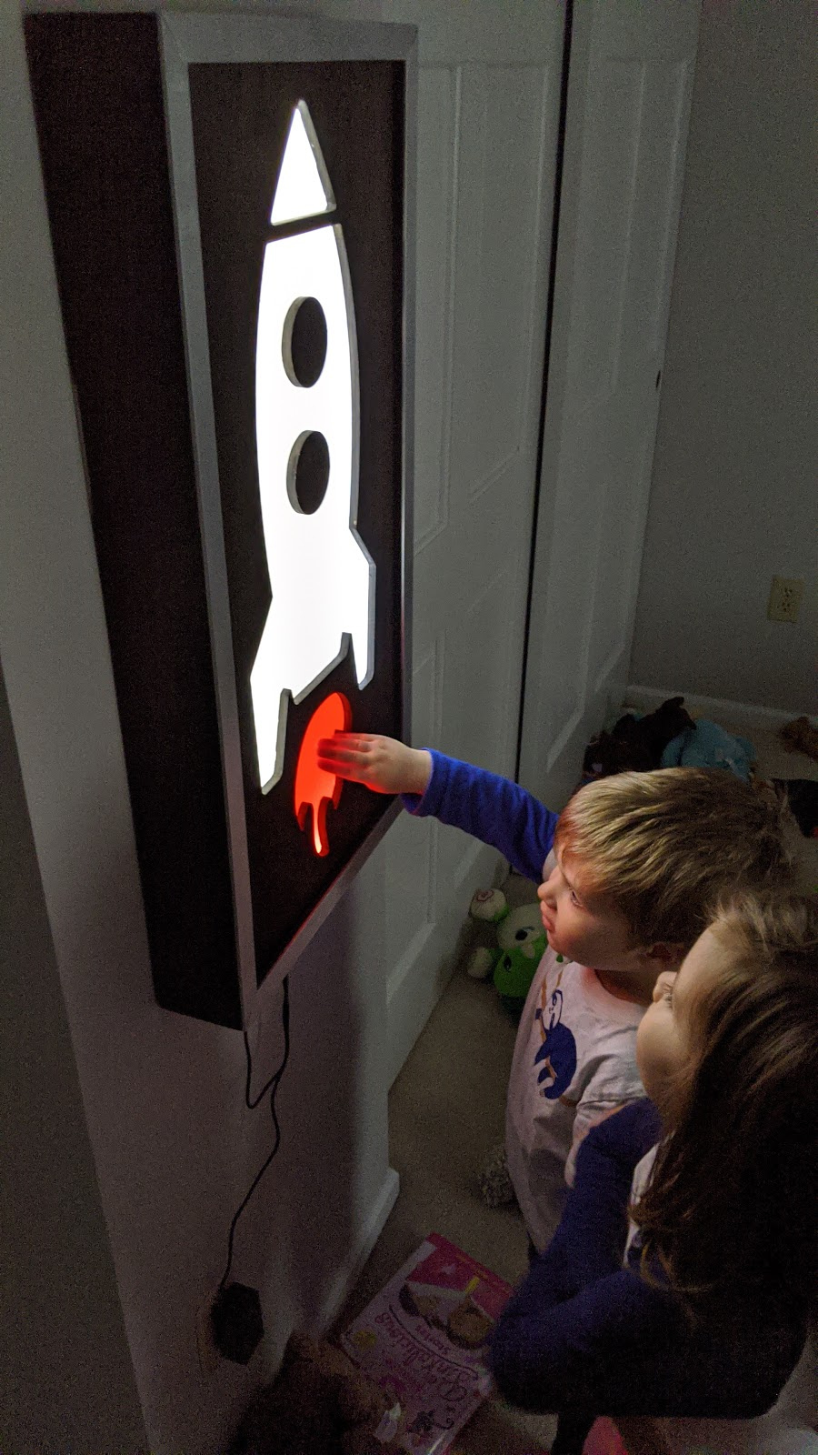
These were lightly glued and held in place with embarrassingly simple holders. The two holes in the white acrylic are for screws to hold the “windows” on the front of the rocket.
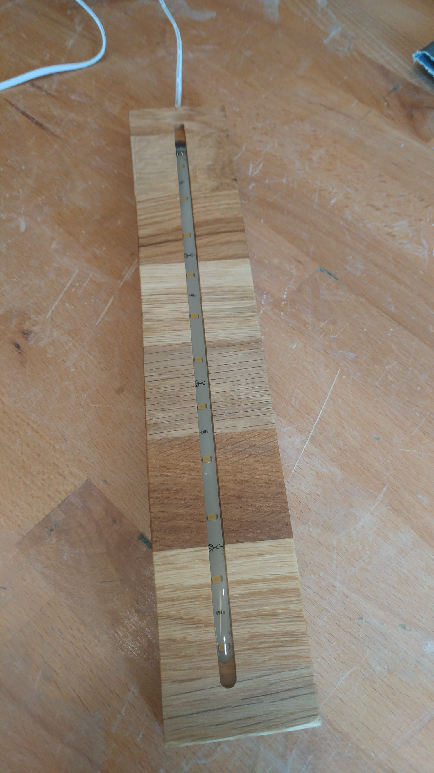
I added a barrel jack connector for power and routed that through a tiny led ring switch to another power connector to make adding the LEDs really easy. I wired the switch led to be always on.
After that, a bright white LED strip was wrapped around the inside.
Closed up the back with those little points to hold frame glass (the name is eluding me). Edit: glazing points.
Aluminum face frame was glued on with E6000 adhesive.
Fusion Design: RocketLight v4.zip (940.2 KB)
CutRocket Rocket: Rocket Lamp by neilferreri
@neilferreri: lucky kid(s)! For extra cool dad points, remake some of those stars in glow-in-the-dark material like @nlichtenberg did
Also, that rocket you cut should go on cutrocket.
My wife and I cut some stencils with her Cricut and she’s doing some glow in the dark painting on the dark wall. Of course that will somehow create a month of no sleep for any of us!
Will do… Still have another plastic entry coming. Like I told you, I’ve been cutting a lot of plastic recently. My 5yr old daughter couldn’t be left out…
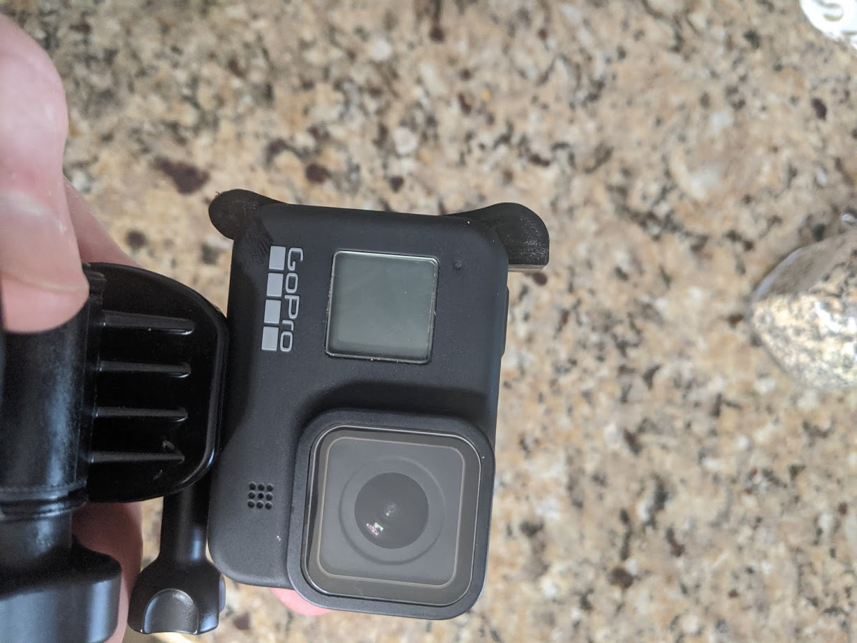
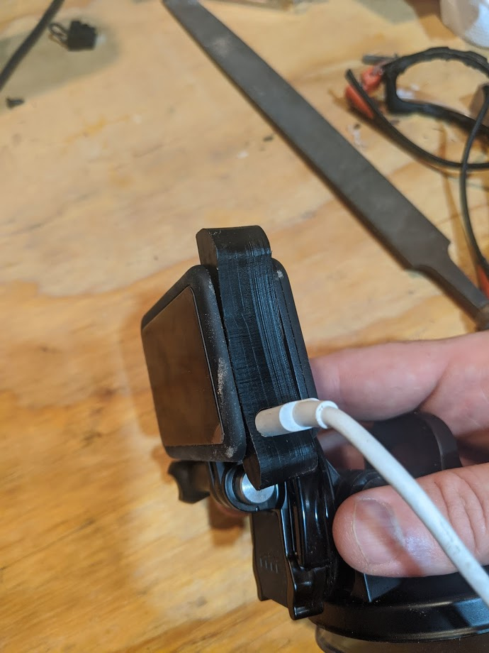
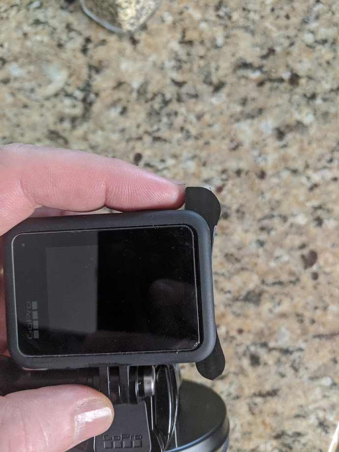
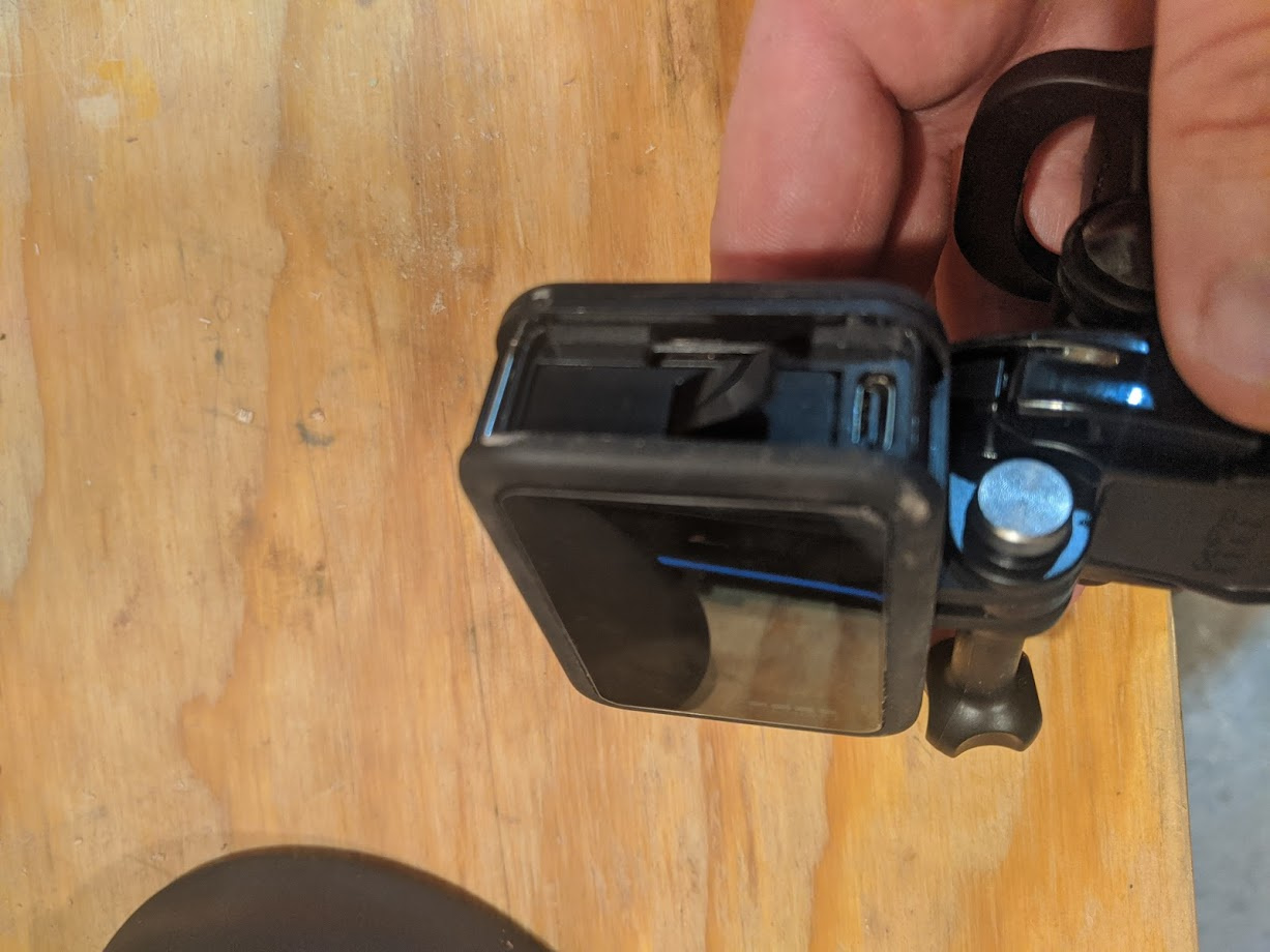
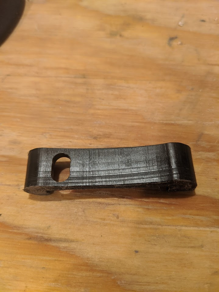
My wifes parents stopped by over the weekend. They were on a 4000 mile motorcycle trip. My father in law just got a new GoPro so he could take videos on there trip. The first day he used it he lost the batter holder so i figured it would be fun to make one. I cut it out of delrin and it ended up working really well. I also added a nob so it was easier for him to located the camera button easier.
Fusion360 link: https://a360.co/3dXS4JO
CutRocket link: https://cutrocket.com/p/5efd372f3832f/
Battery_Holder.nc (58.2 KB)
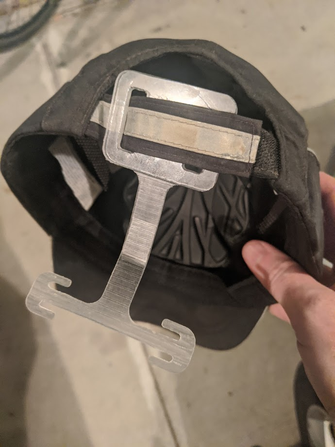
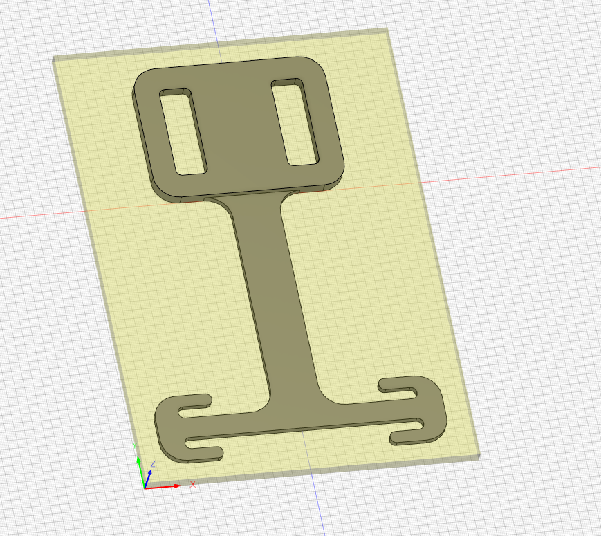
At work i wear a mask all day and it hurts my ears. So i started using a 3d printed ear saver that hold my masks off my ears. This worked but i kept loosing it and braking them. So i decided to make one that attached to my bump cap that i have to wear. I have been using it for the past 2 weeks and i have not lost it and my ears do not hurt
Material: Polycarbonate 0.125 thick
fusion 360 link: https://a360.co/2NJl4tU
Cut Rocket link: https://cutrocket.com/p/5efd3d15ac4c6/
Delrin Bushings and Associated DIY Fixture Vises and DIY Lapping Tool
For this challenge, I would like to submit a seemingly simple project that I’ve been working on for the past 2 weeks: bushings made from 1.250" Delrin. I said seemingly simple because there were plenty of hurdles to overcome throughout this process.
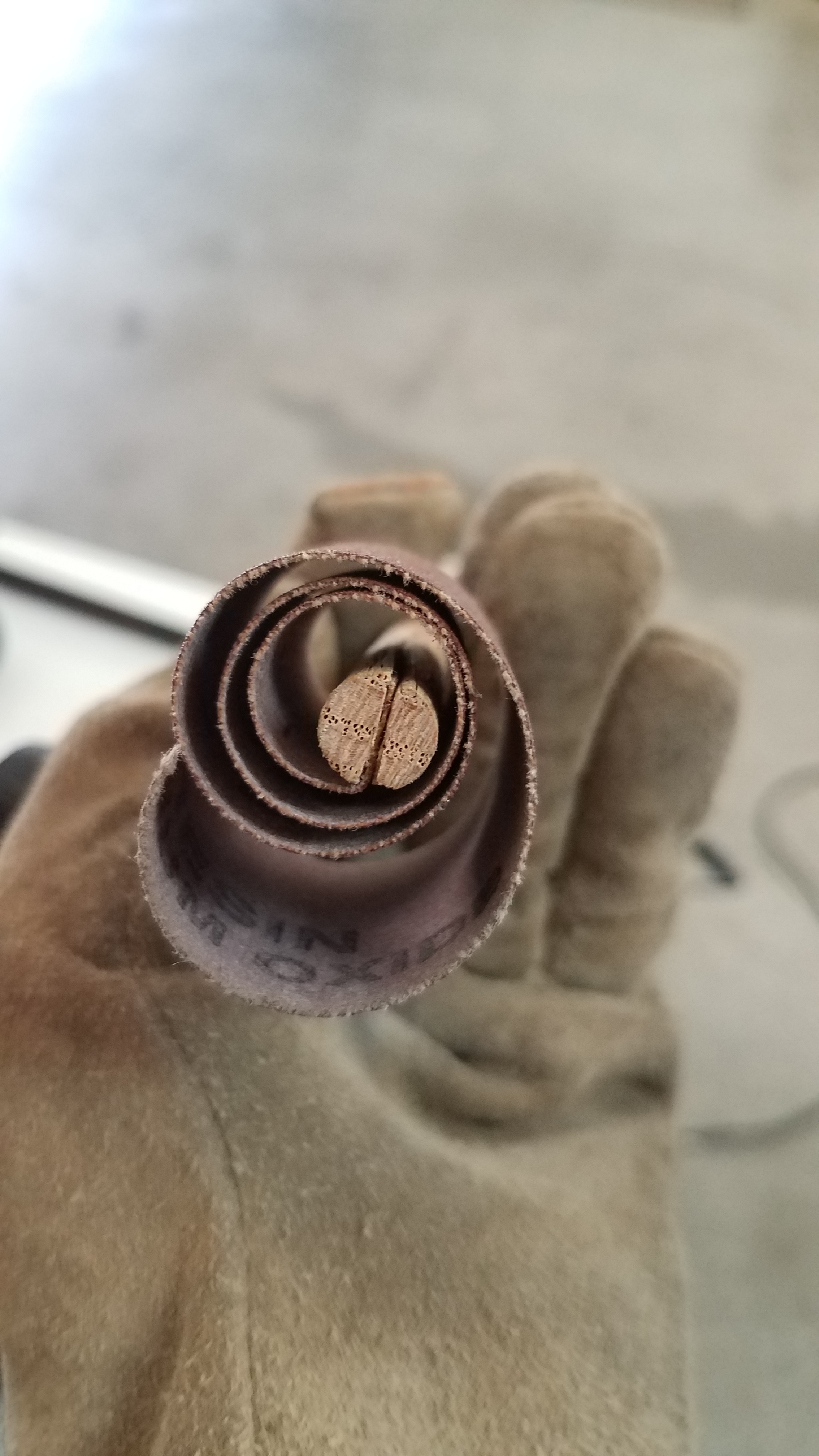
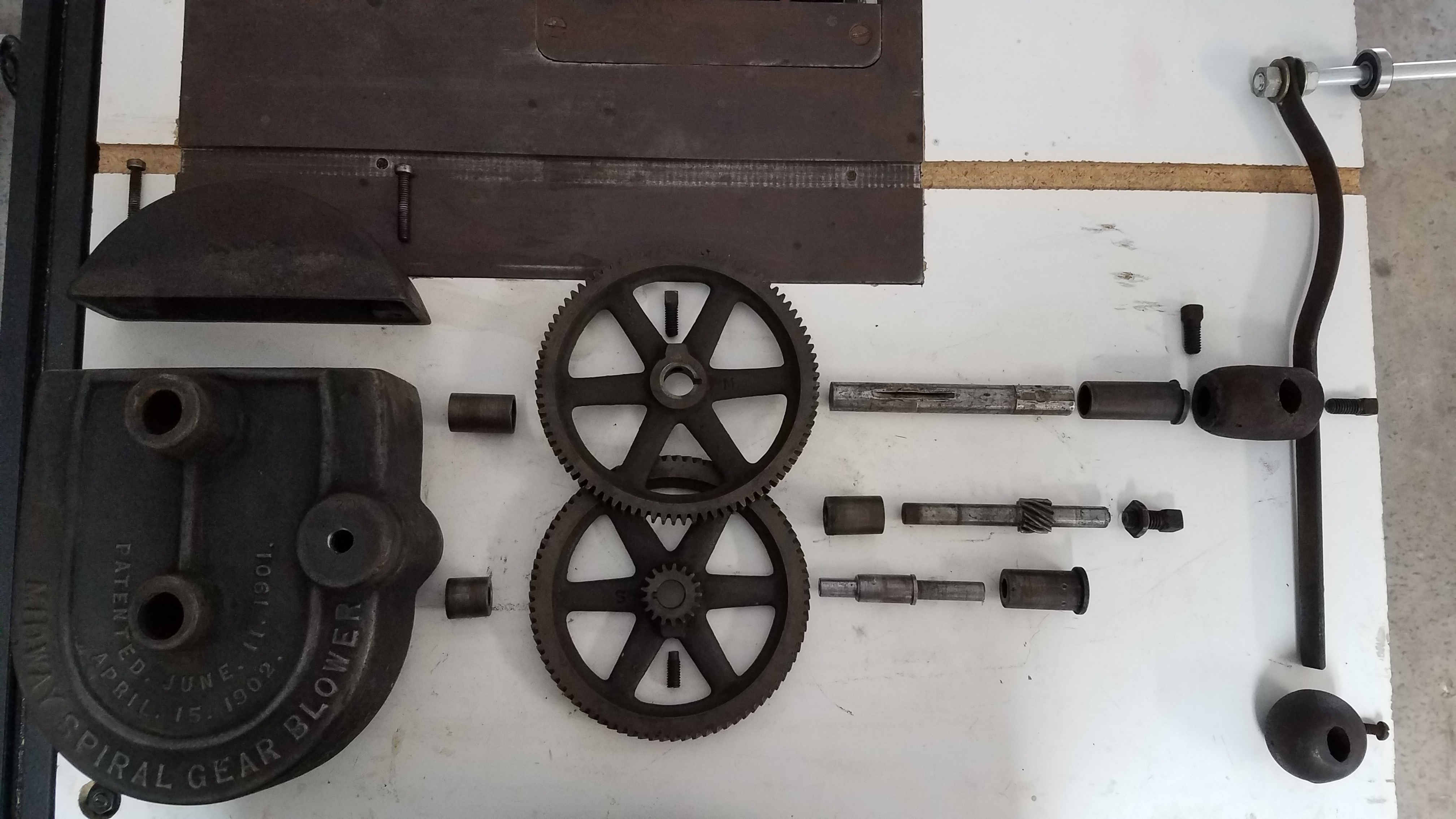
Before I cover the problems I encountered, let me first explain what these bushings are for. I have a blower from an early 1900s metal forge which has worn out bushings.
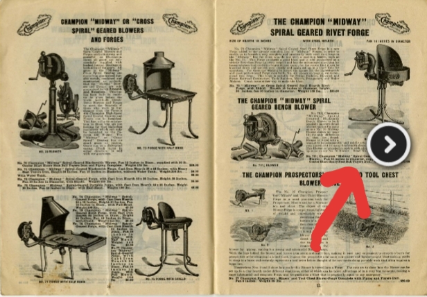
I spent a great deal of time taking this whole assembly apart and realized the original bushings were made of steel. I wanted to make the new bushings out of something softer as to not wear out the shafts of this blower any worse than they already were. At first, I was going to use brass but I realized Delrin was it a lot cheaper, easier to machine, and is also used to make bushings. Let the fun begin😏
Problems
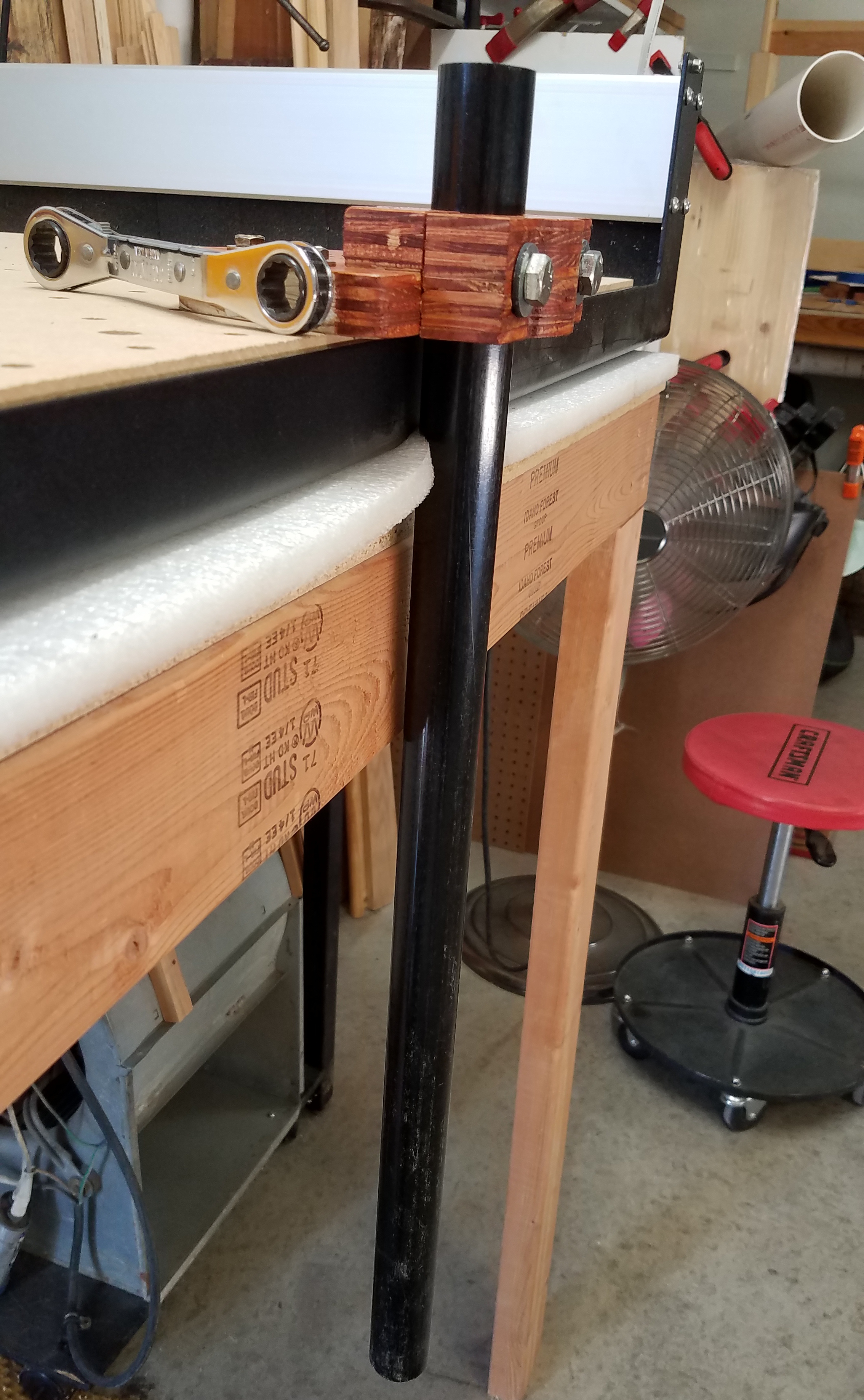
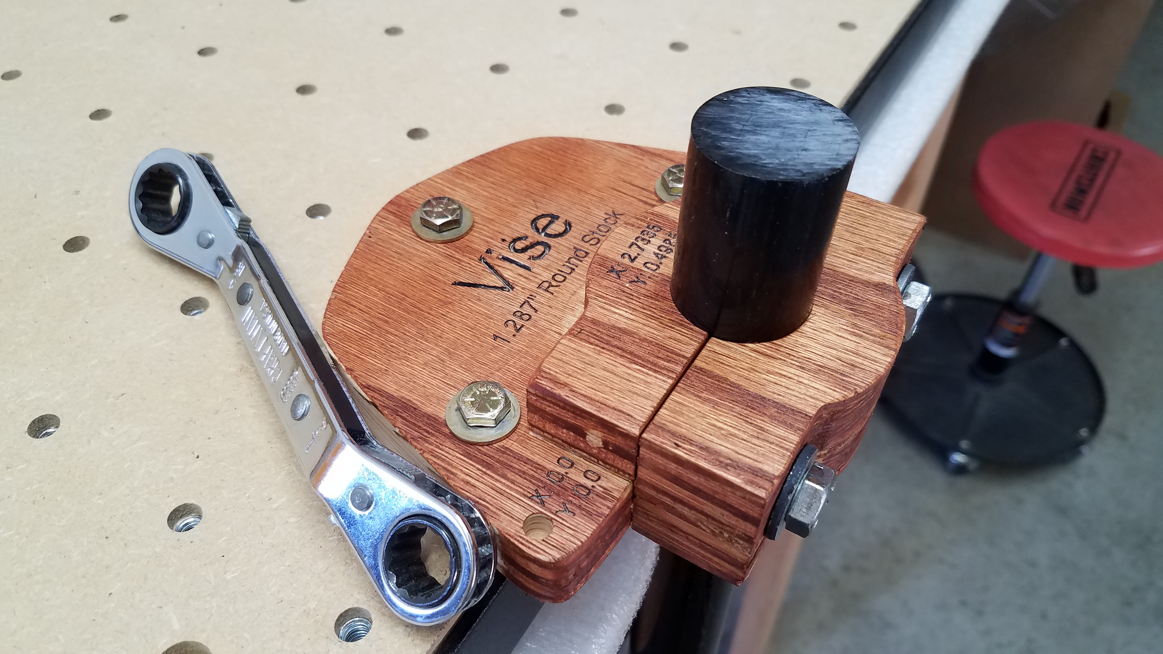
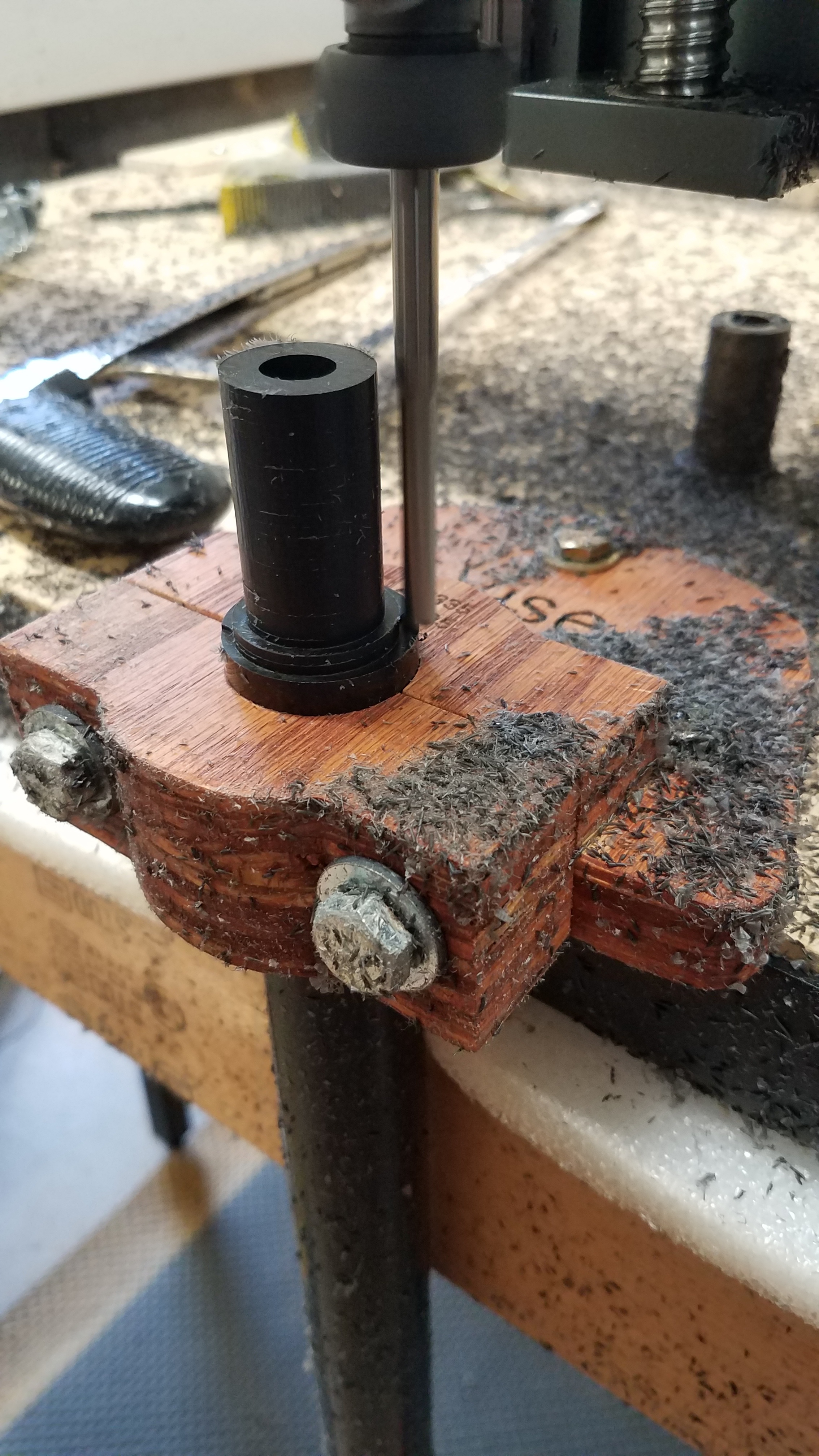
To overcome the work holding problem, I created a wooden vise that overhangs the front of the Shapeoko. This vise utilizes a quick zeroing locator hole which corresponds with the machine’s front center rapid travel location. This allows me to slide a 1/4 inch dowel rod from its position in a loose collet and into the hole before tightening the 3 securing bolts. Then I run an indicator across the front of the vise (with the front jaw removed) to verify alignment along the x-axis. This indicator hole allows me to quickly resume work after switching zeros for other programs. Now with this vise, I can quickly hold the piece of Delrin at any height needed for my different length bushings.
To overcome my cutter selection problem I purchased a 1/4 inch 3 flute End Mill with an overall length of 4 inches. Before machining the longest bushing of 2.2 in I realized I was significantly close to maxing out the Z travel of my machine. I had already programmed my clearance height to 0.010 inches. However, the G53 code at the beginning of my program commanded the machine to make a Z movement -0.197 inches before moving to the x and y plunge point. If uncorrected this would cause a gouge across the top of my part within the first few seconds of the program. Additionally, the M02 command at the end of the program again caused the Z-axis to move (-0.197 inches I suspect) before traveling to the back of my machine. If uncorrected this would also cause a second gouge across the top of my part. A quick call tech support helped me understand the expected G-Code movements; thanks, Brandon. Next, I did a series of test runs away from my part as I removed the G53 line of code and the M02 line of code. After I was confident in the expected outcome I changed my zeros back to my part and proceeded to cut the bushing.
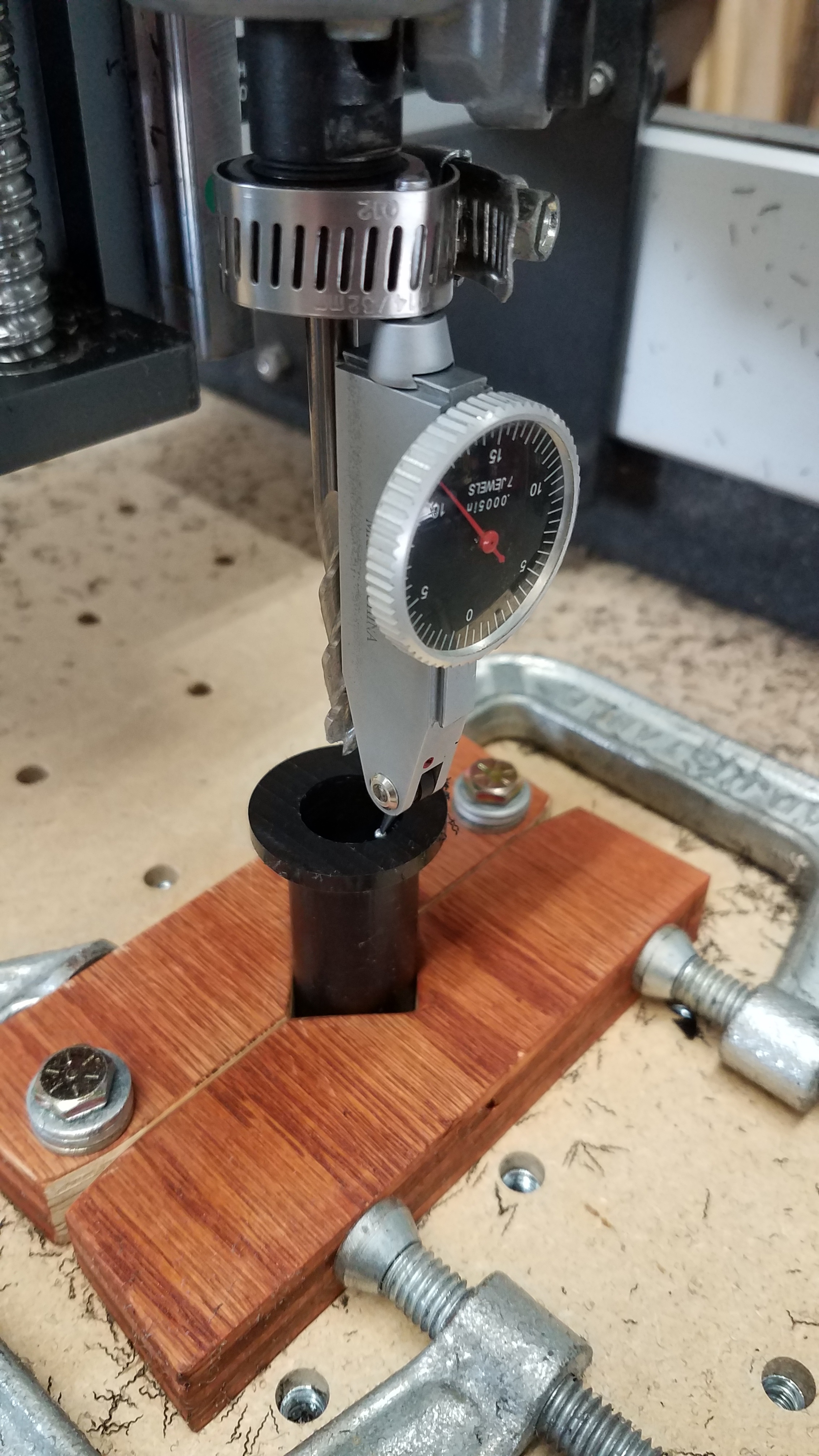
After operation one finished for each bushing I cut the bushing free of the material with a hacksaw. This brings me to the third major problem; how do I hold a small round object so that I may face the end? My vise only holds the larger round stock. I designed a simple V block vise which I could mount anywhere on the table.Note: a hose clamp can make a quick job of mounting a dial indicator 
And now on to the fourth problem: holding tight tolerances. I started with running my spindle speed at 18000 and a feed rate of around 60 inches per minute. However, I quickly realized things were not rigid enough to hit tight tolerances and go that speed. The major drawback that I faced was cutter run-out. I’m sure the collet was partially to blame, but I noticed that I can wiggle the spindle nut on my Carbide 3D router forward and backward as well as side to side when tightened. This leads me to believe that the spindle bearing in my router is going bad (I’m not sure how tight this was when new). If anyone has any suggestions on fixing this please let me know. As for my project I wanted to continue so I slowed my feeds and speeds extremely.
Contour Operations for both ID and OD
Feed rate: 15 inches per minute
Step Down per Pass: 0.034 inches
Plunge rate: 4 inches per minute
RPM: 10,000.
I was still able to get chips from the Delrin and no melting. The surface finish was okay but not like you would see on the lathe.
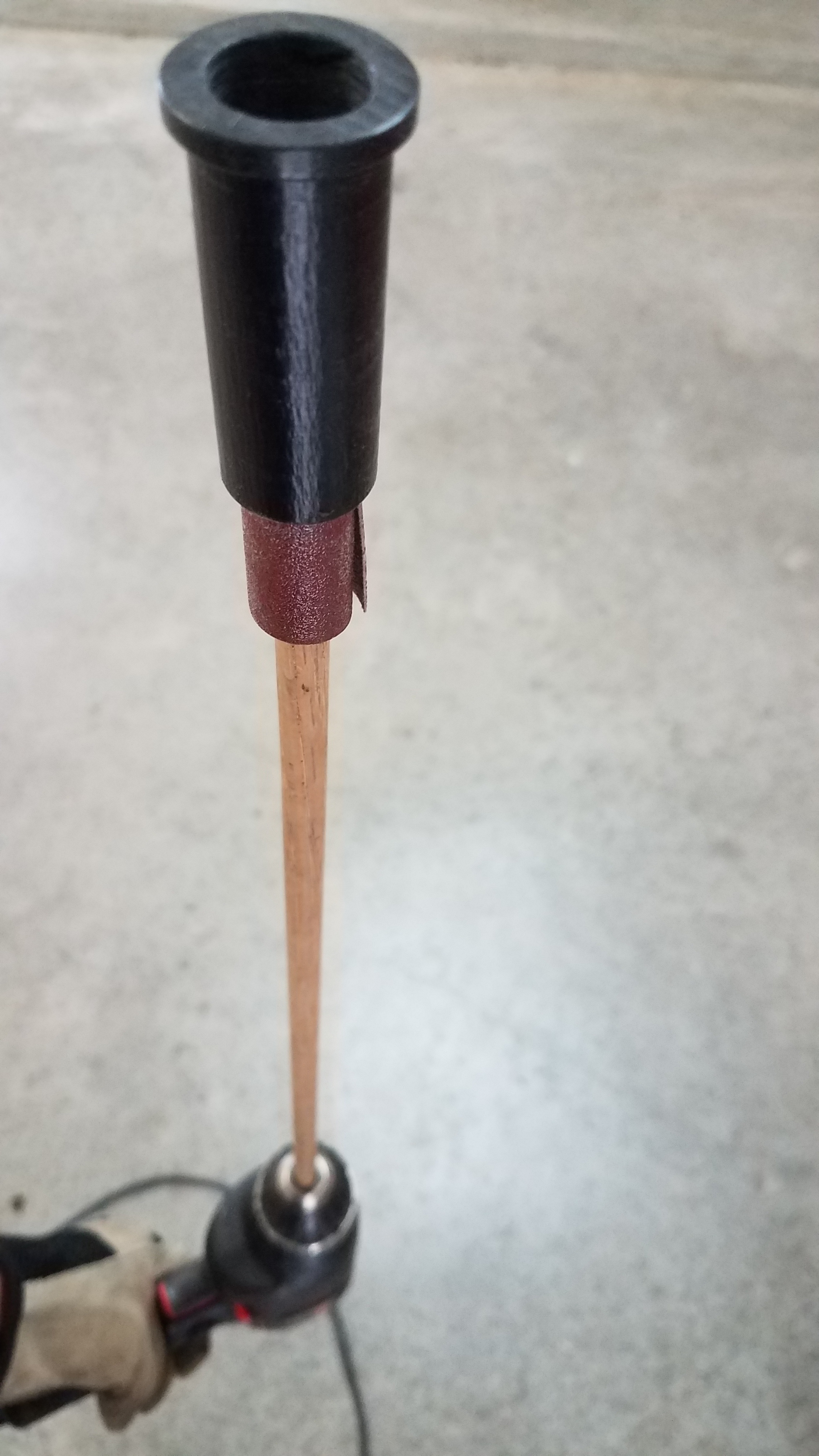
I would like to fix the spindle bearing and try this project again to see what improvements can be expected in surface finish and how much faster I could push the feeds and speeds. To compensate for the run-out and spindle wobble I created oversized and undersized geometry for the OD and ID respectively. For each additional bushing (each one varies in size), I copied the previous program and saved it under a different file name so that I could make adjustments as needed without deleting or altering a proven program for the previous bushing (in case I ever need to remake these).The final problem I’ve had to overcome was the tolerance between each shaft and bushing. I created a makeshift lapping tool from a wooden dowel rod and a piece of a broken belt sander belt. This process slightly expanded the ID of each bushing until it would freely spend on the associated shaft.
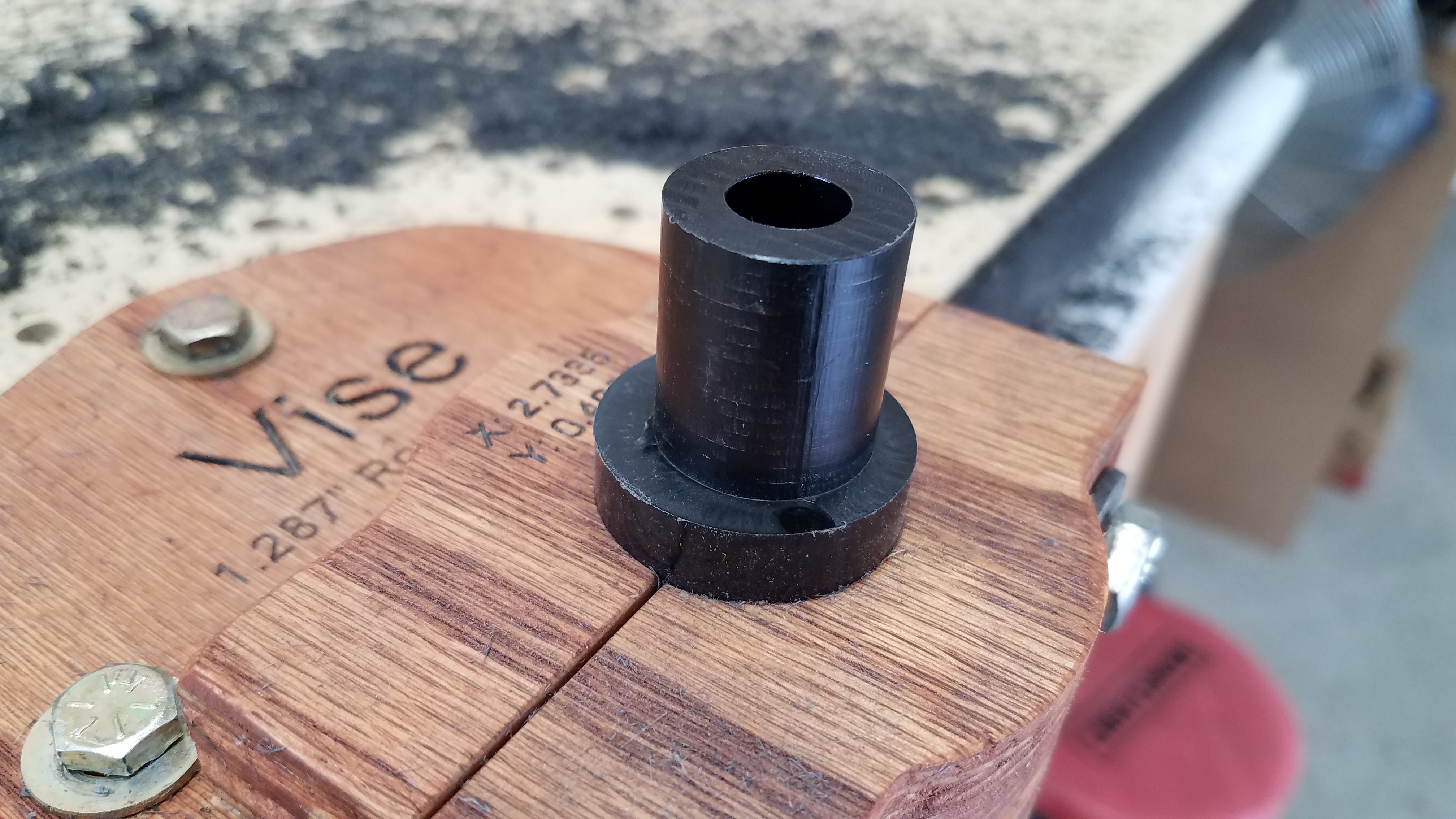
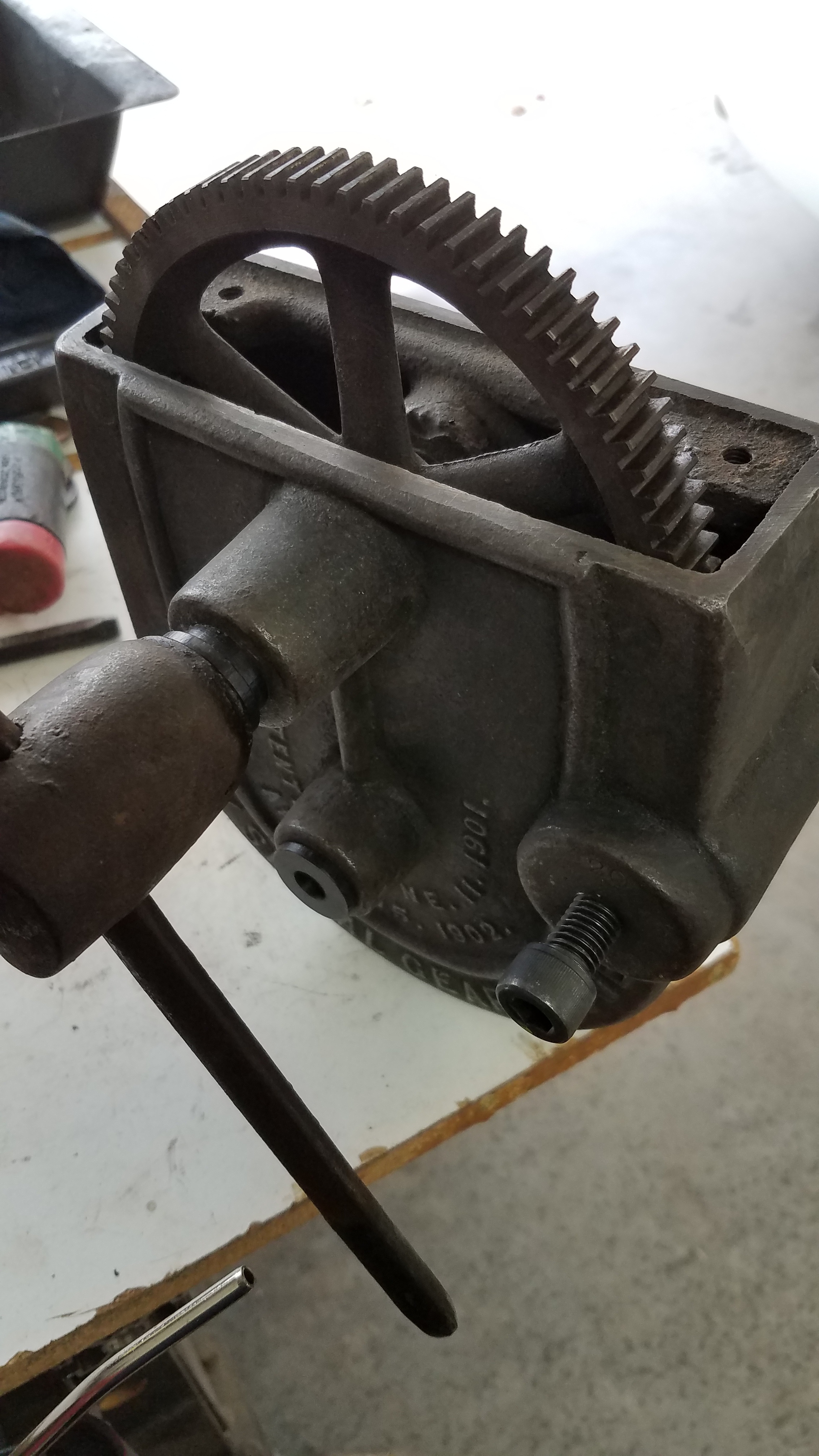
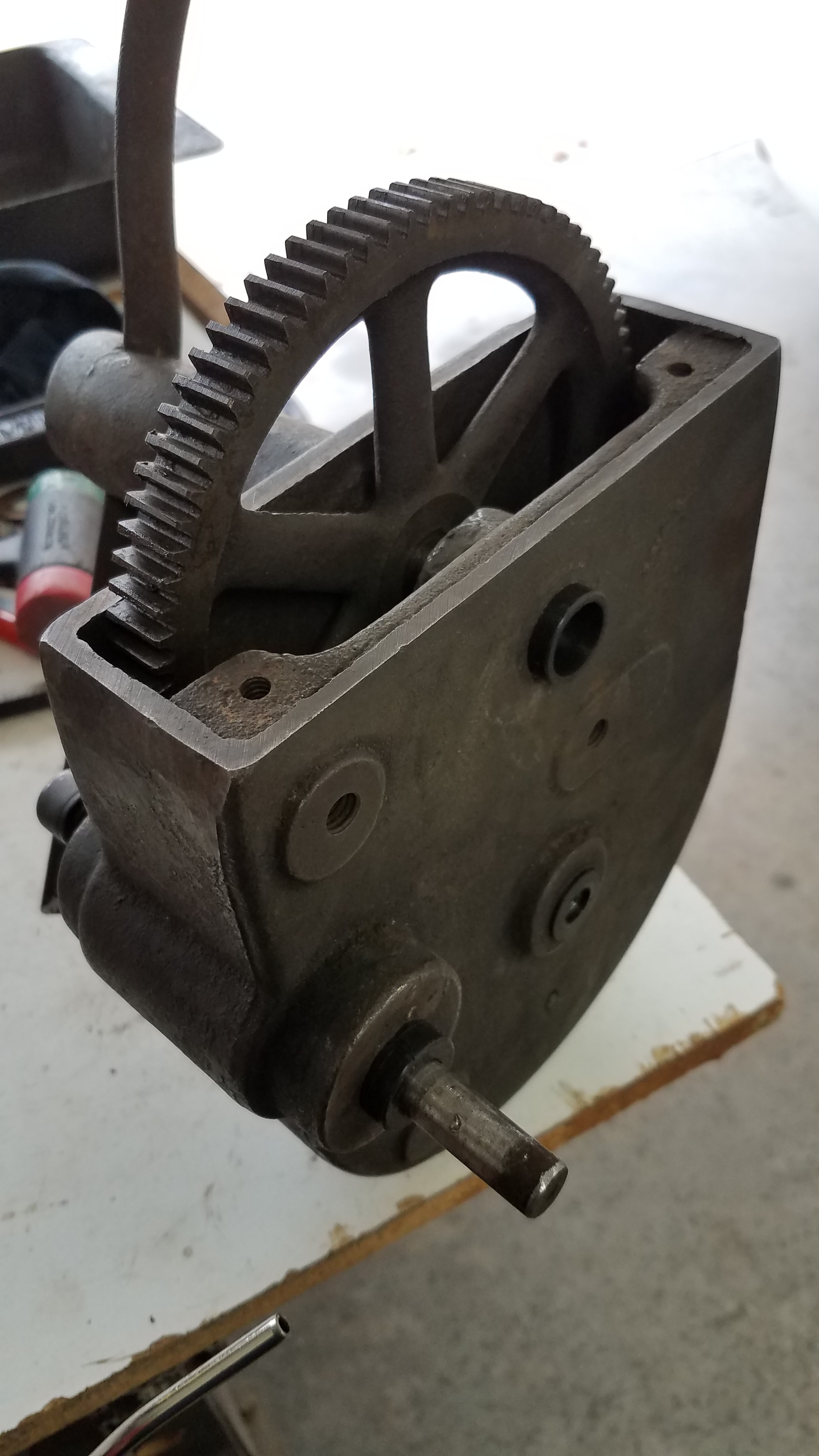
And as @Griff would say: where’s the pic, or it didn’t happen (pretty sure I’m quoting the correct person, if not, my apologies). Here is the disassembled puzzle with old bushings, followed by the finished project’s installed Delrin bushings that were fully designed in Carbide Create and machined with my Shapeoko.
Carbide Create CAD/CAM files: 0.880 OD Bushing Vise.c2d (49.6 KB) 1.287 OD Delrin Vise v2.c2d (2.3 MB) Middle shaft - hat bushing oversize.c2d (1.1 MB) Middle shaft - sleeve bushing oversize.c2d (2.2 MB) Outer shaft - sleeve bushing (started with oversize comp).c2d (2.6 MB) Upper shaft - hat bushing (2nd operation_hat OD).c2d (1.9 MB) Upper shaft - hat bushing (started with oversize comp).c2d (2.7 MB) Upper shaft - sleeve bushing (started with oversize comp).c2d (2.7 MB)
CutRocket Link: https://cutrocket.com/p/5efdedf60f0f4/
-James All
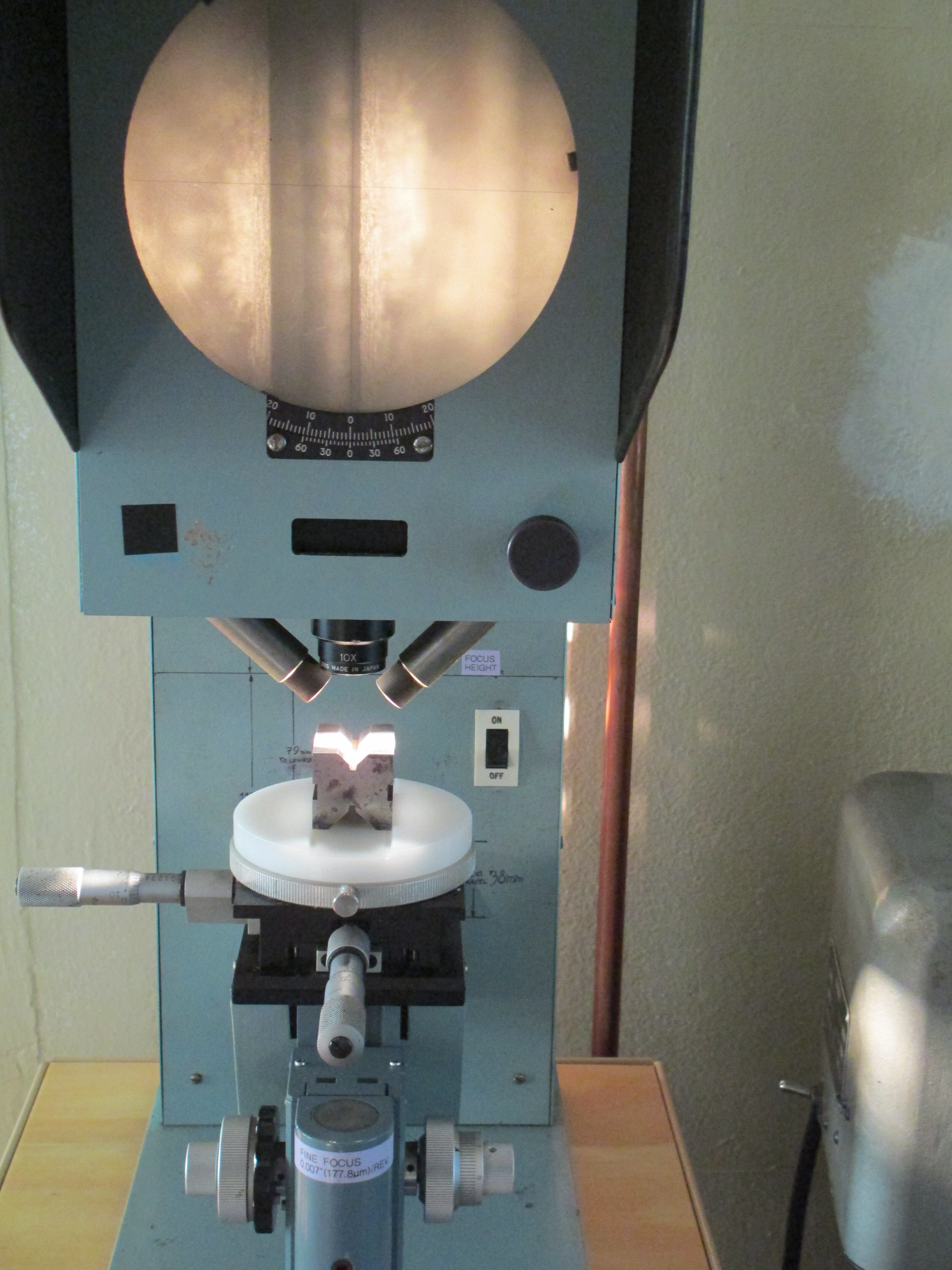
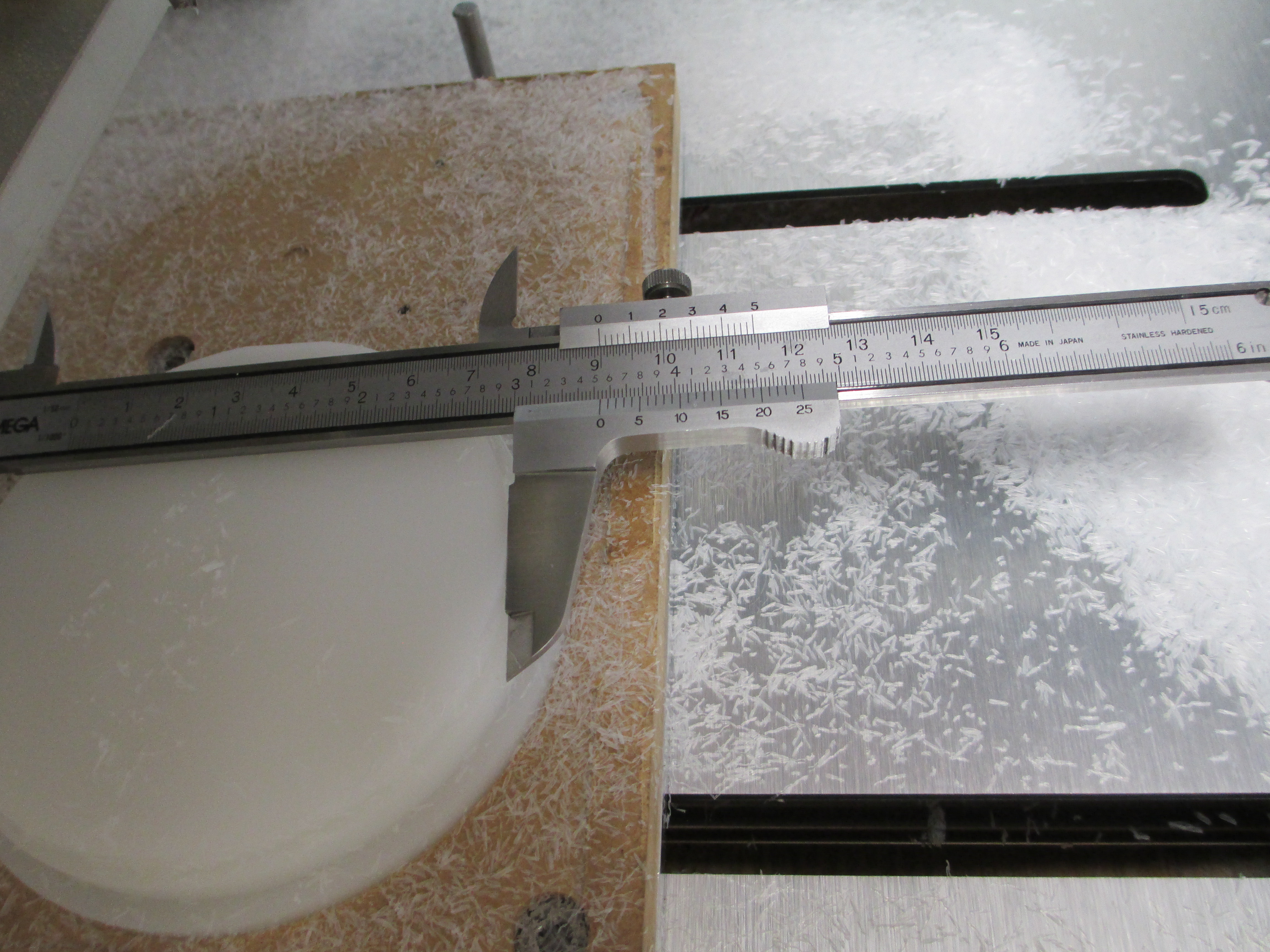
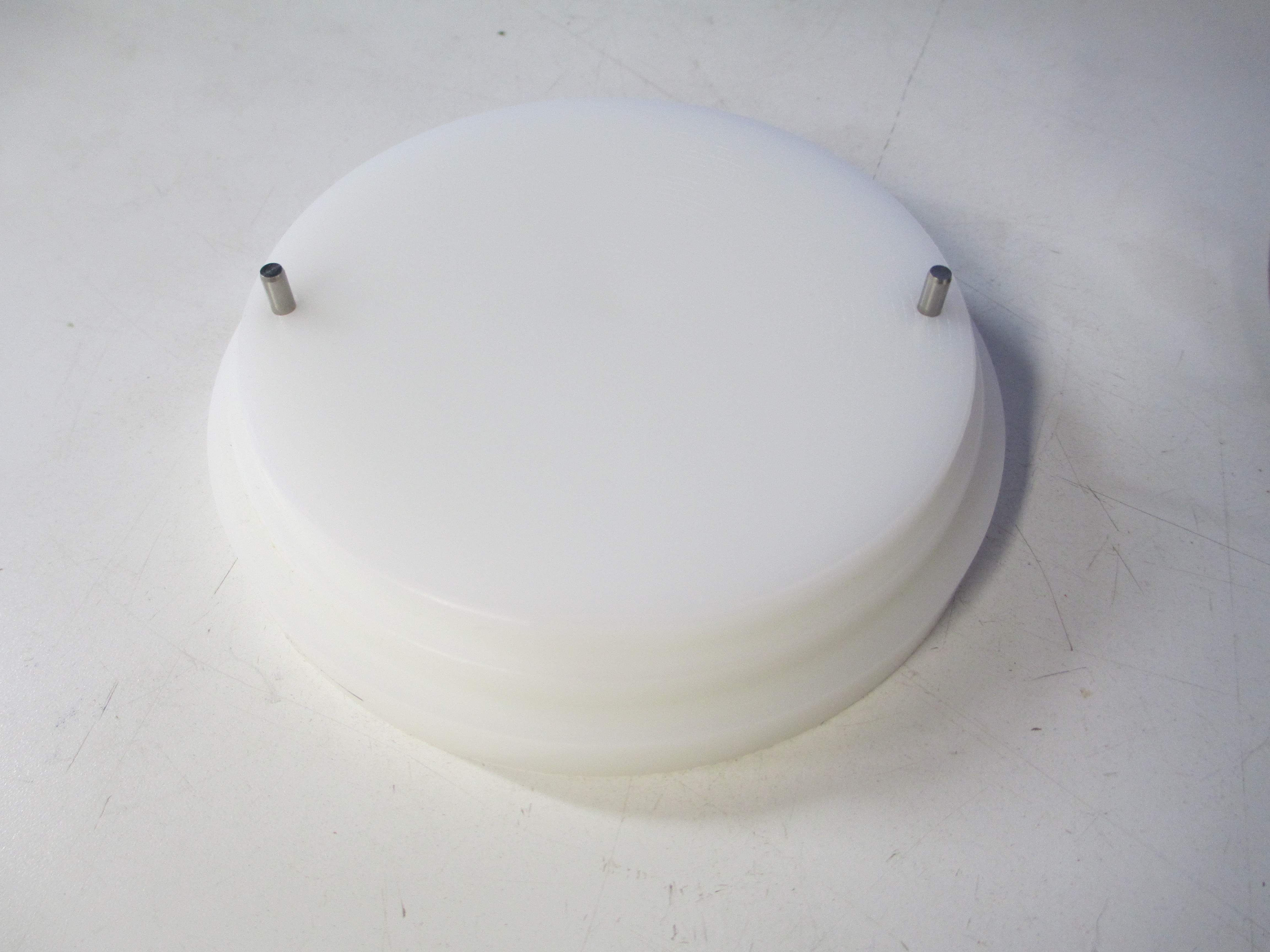
I finally got the material in that I was waiting for, so here is a new project. This is a riser/fixture for a vee block on one of my optical comparators. The finished product looks like this:
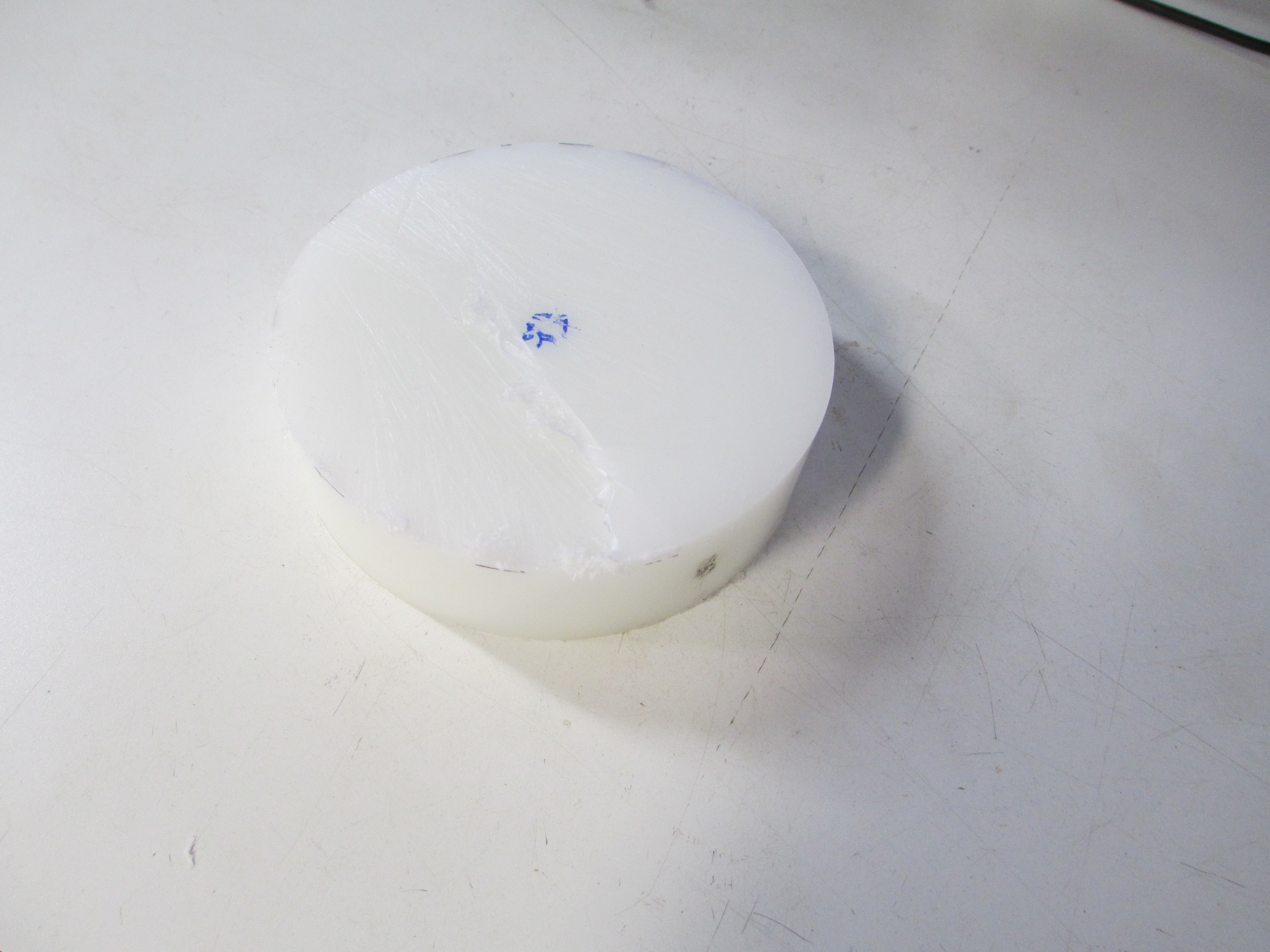
The stock is HDPE, as it is easy to machine, holds dimensions well, is moderately priced, and has a reasonable ‘feel’ for the application. Delrin is too pricey, but Oh so sexy. 4"nominal round bar (101.6mm, -0, +0.5mm is the spec) was used to minimize waste.
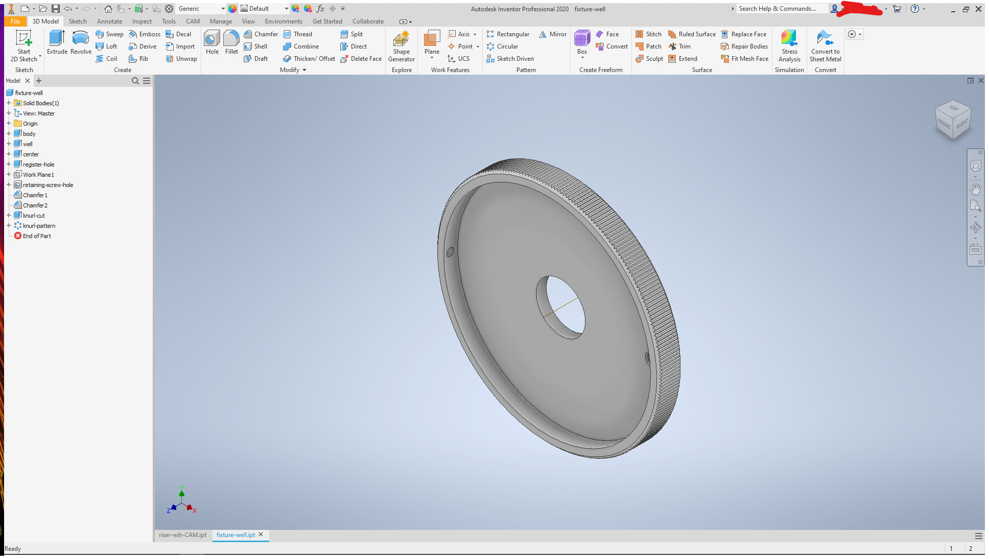
Lots of pics here, because I am that kind of nuts. The part was modeled in Inventor, but Fusion360 is real close.
For this kind of work, where the fit needs to be pretty close-- better than 0.1mm-- it is easiest to model what you fit to, then use offset parameters as needed for clearances. So, the aluminum well on the stage was modeled
and used as the basis to derive a solid for the riser
by using the well as a cutting tool
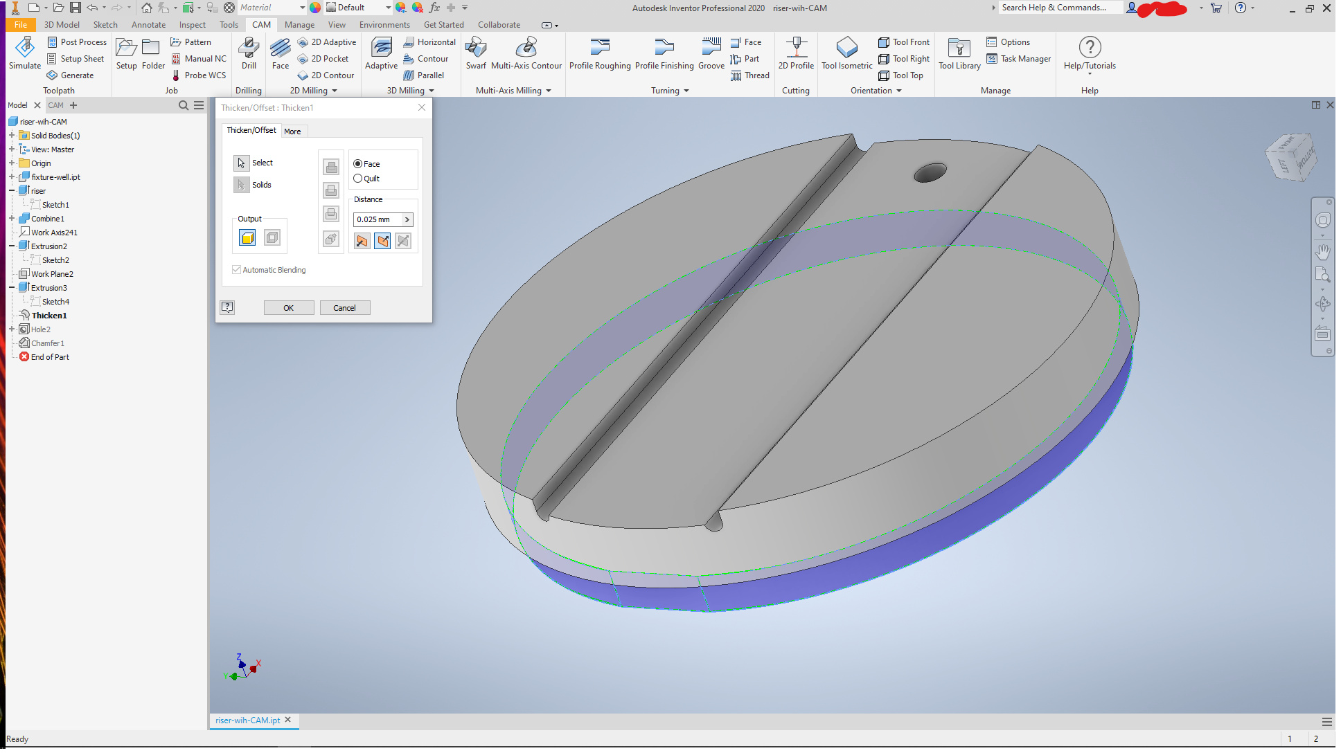
A flat was placed for the holding screw to seat to
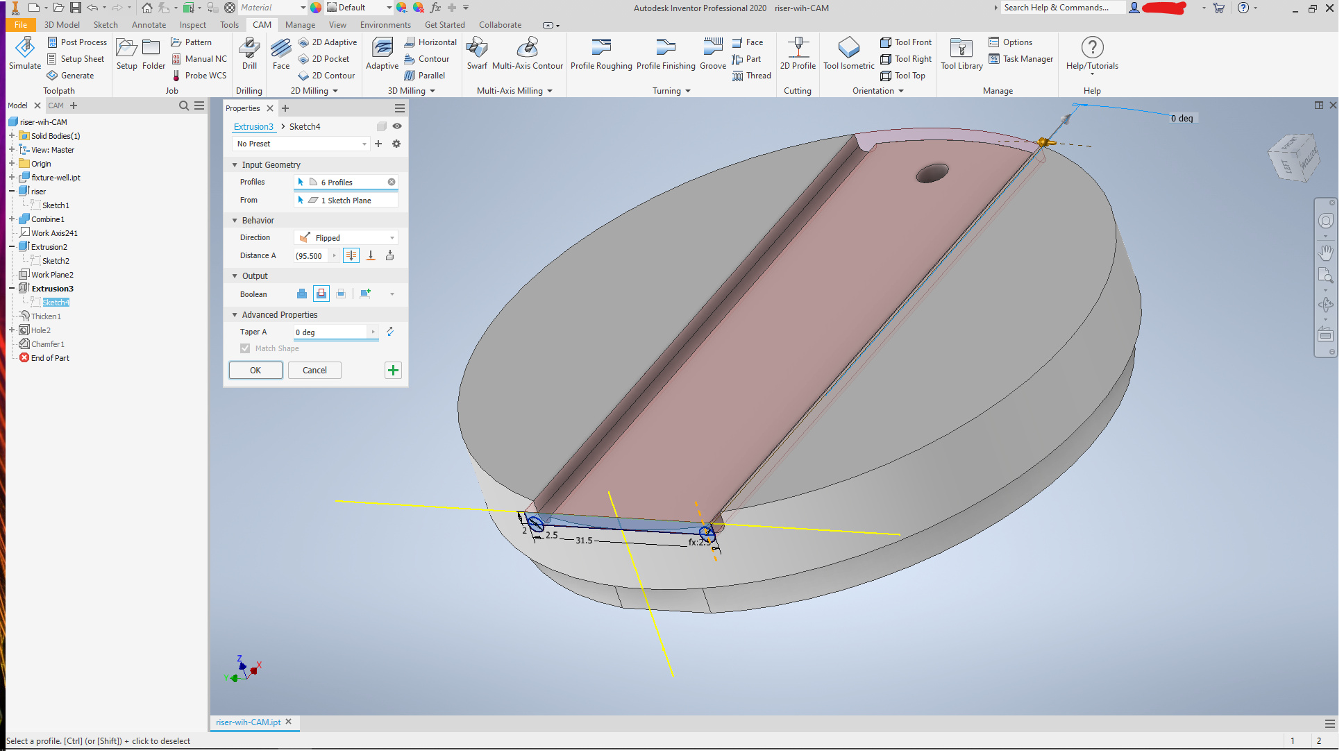
and a seat cut for the vee block, with reliefs at the corners to keep crud from binding it up
and clearance was added for inserting into the plate by offsetting the OD at the bottom
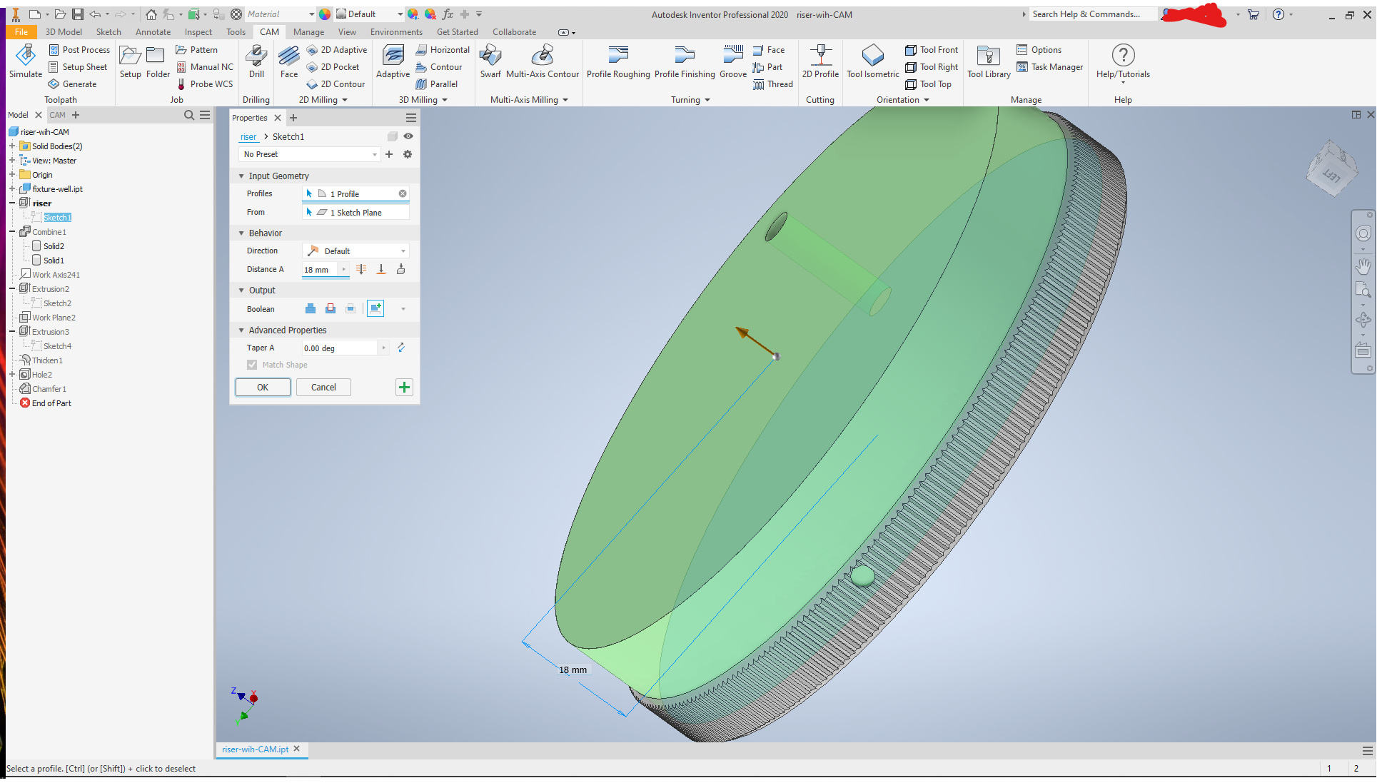
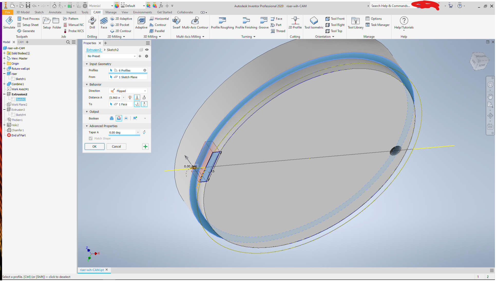
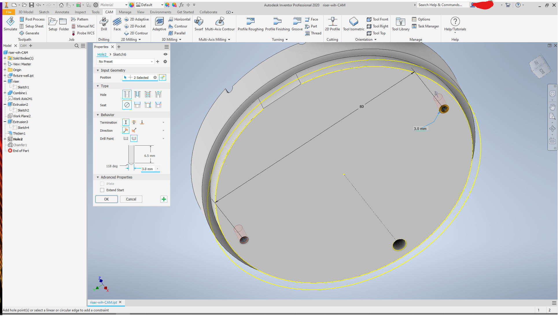
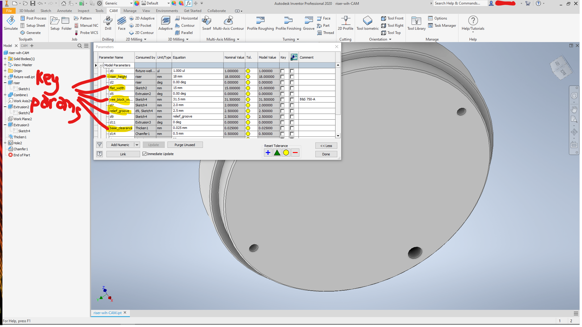
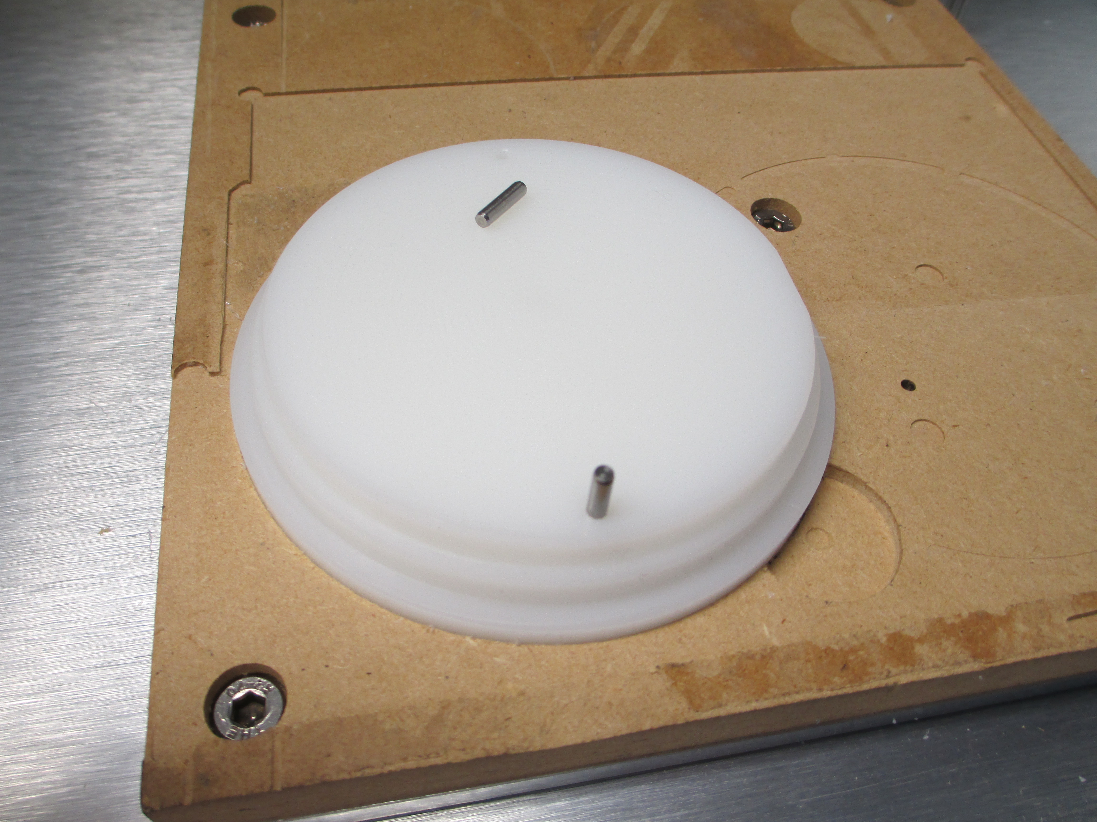
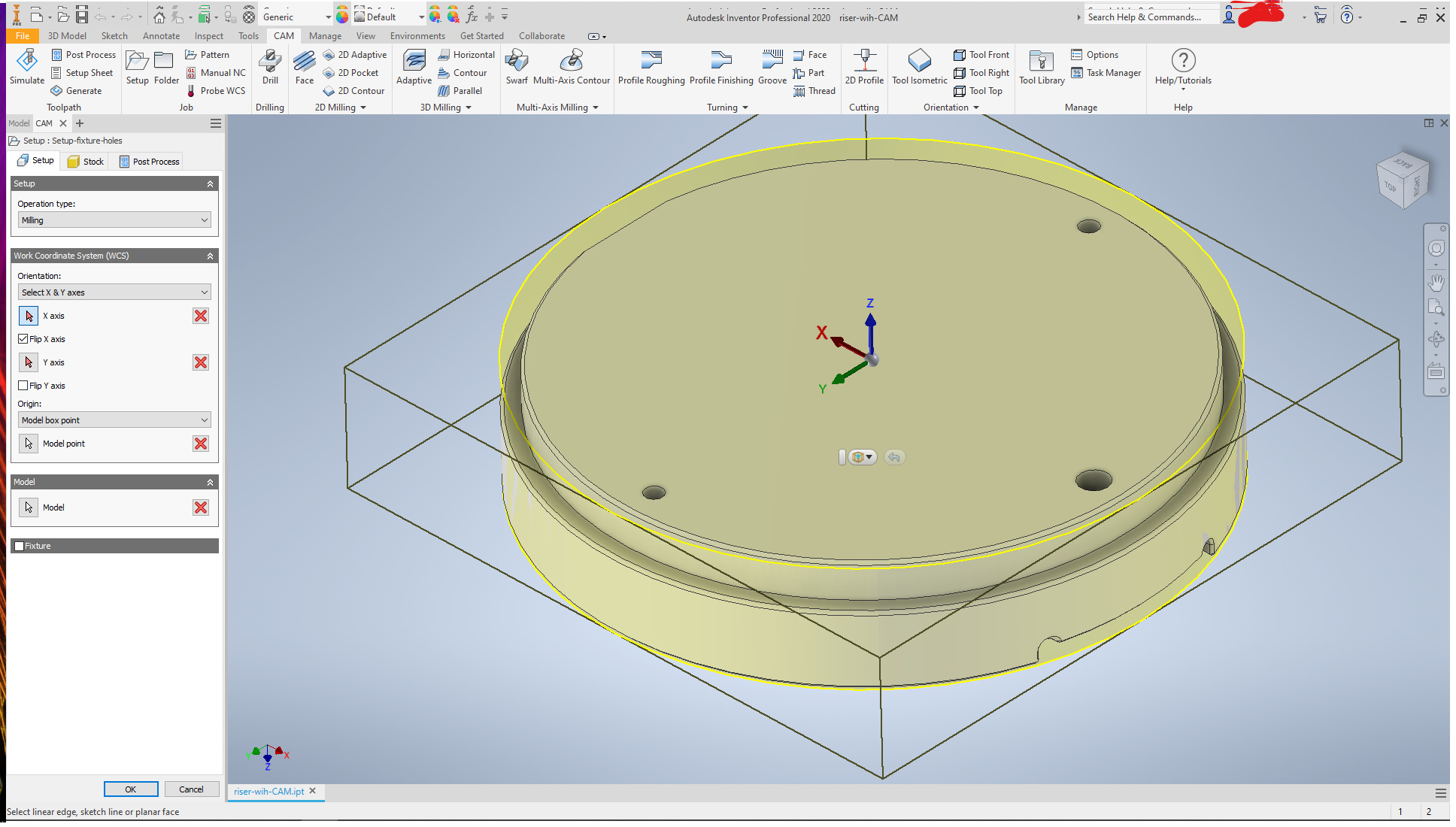
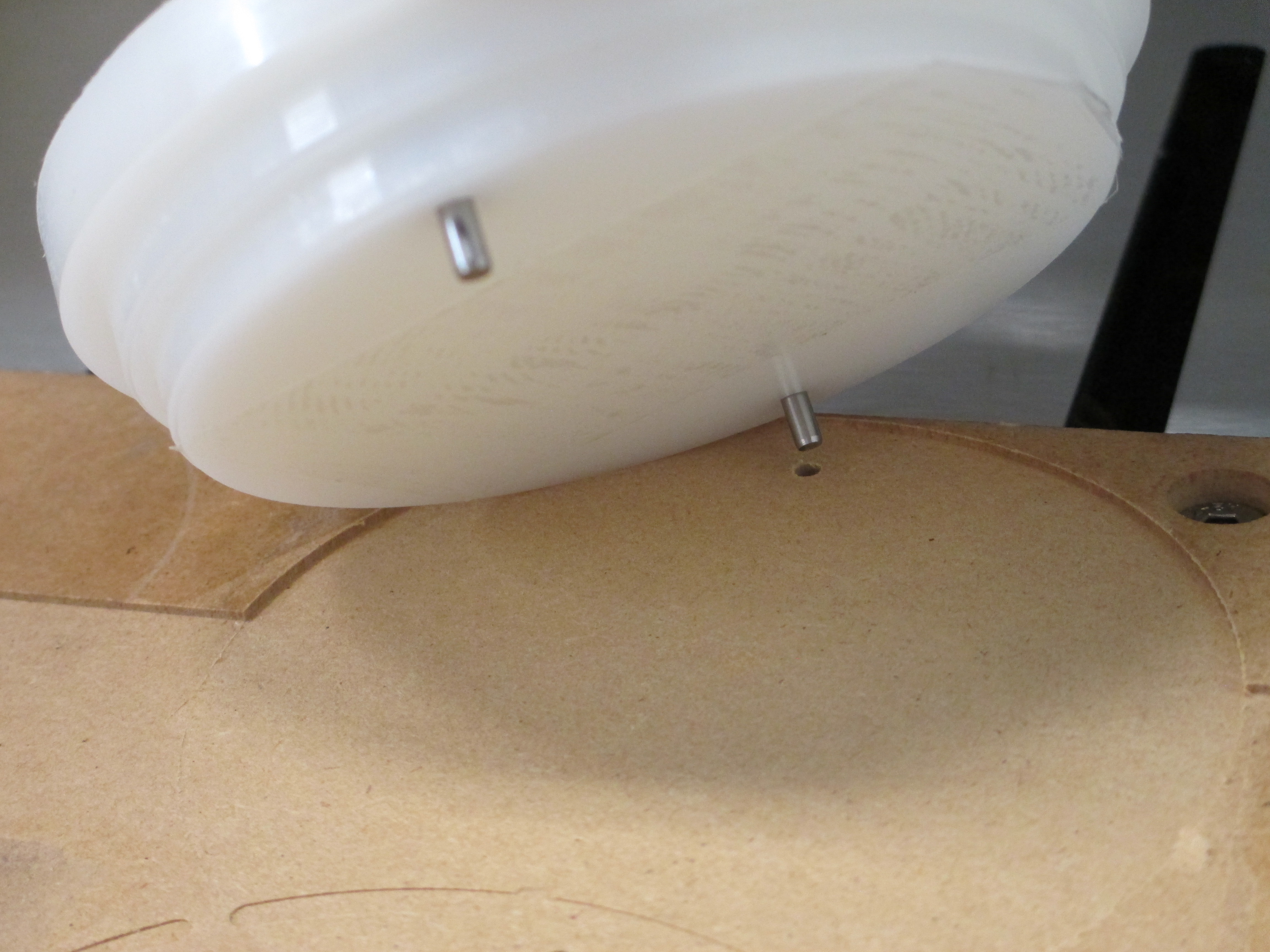
And, as part of the setup for machining (this isn’t the base model— this is a working copy for doing the CAM) holes set for 3mm diameter dowel pins. This allows the two sided machining to be done with proper alignment.
You can see that many of the key features were defined as named parameters to make them easy to work with. There were only a few things where the named parameters were used to derive other features (the clearance grooves coming to mind)
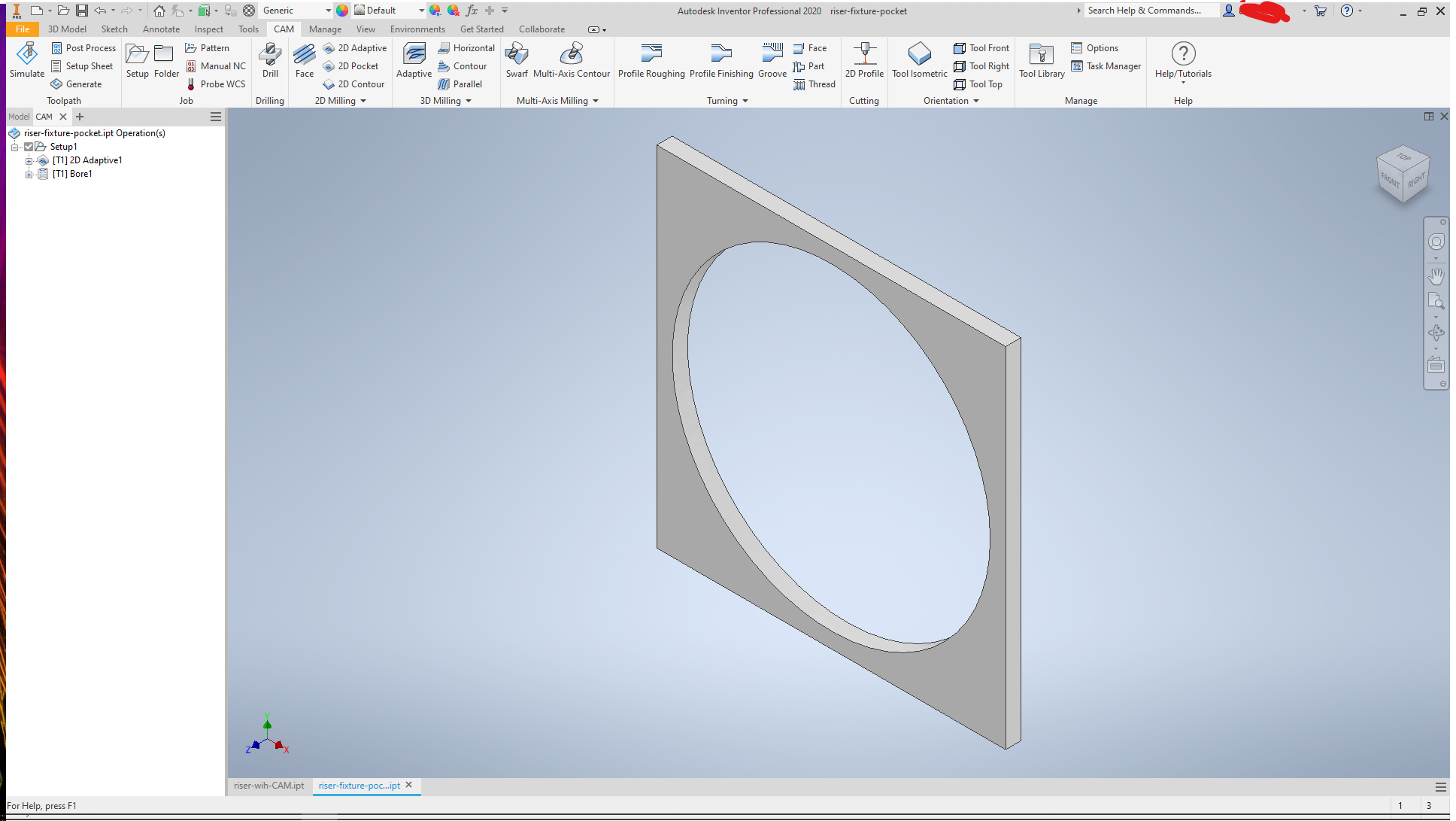
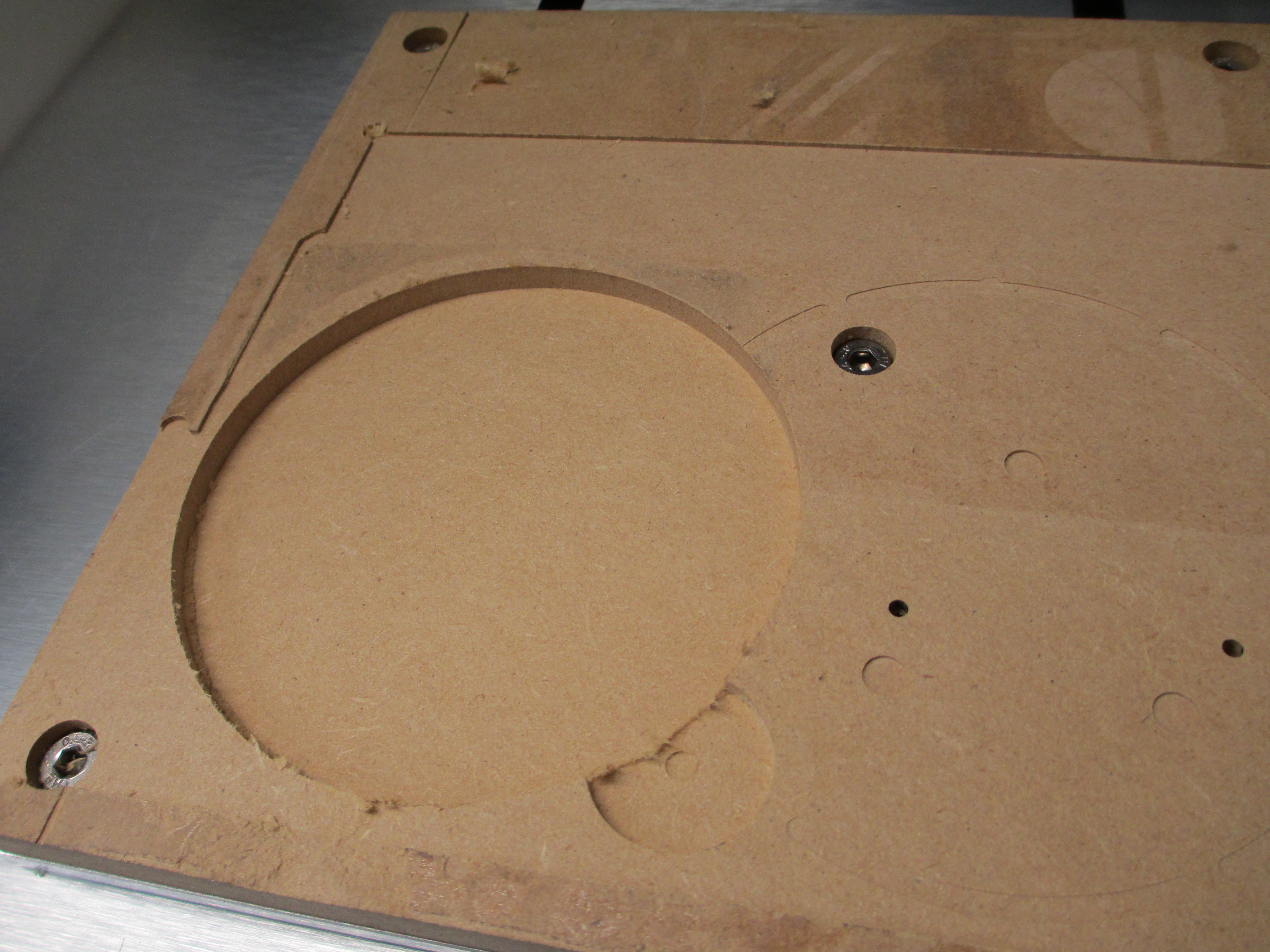
Another simple model was made to machine a pocket to hold the base stock. It was used several times, as after the initial cut (intentionally too small) the size was offset to bring the pocket up to the correct size.
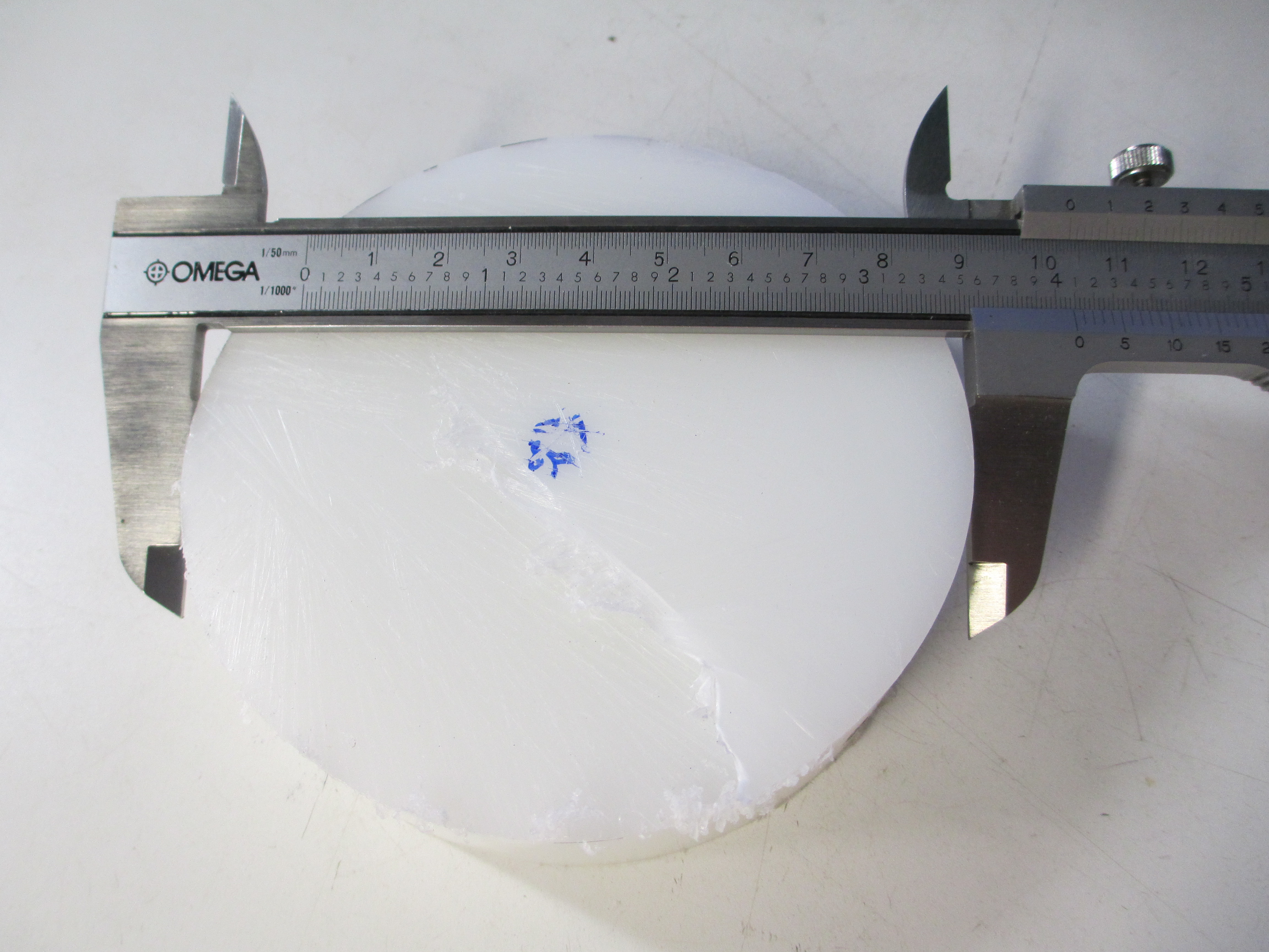
I think it took three iterations, as the base stock is a bit less round than I would have liked (out of spec, actually-- 101.6mm nominal, -0, +0.5. Actual was 103.7mm one way and a whopping 104.9 max.)
The stock was a snug press fit and no other holding was used.
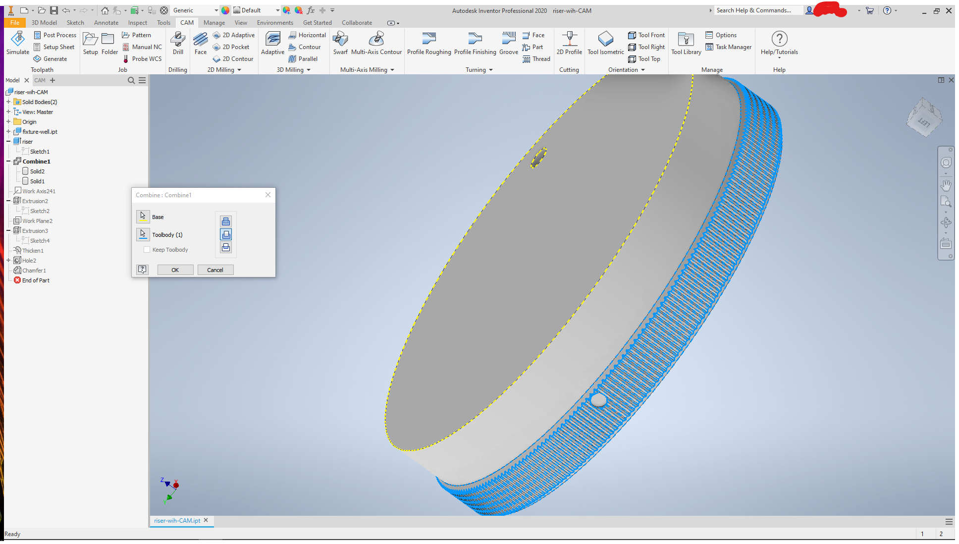
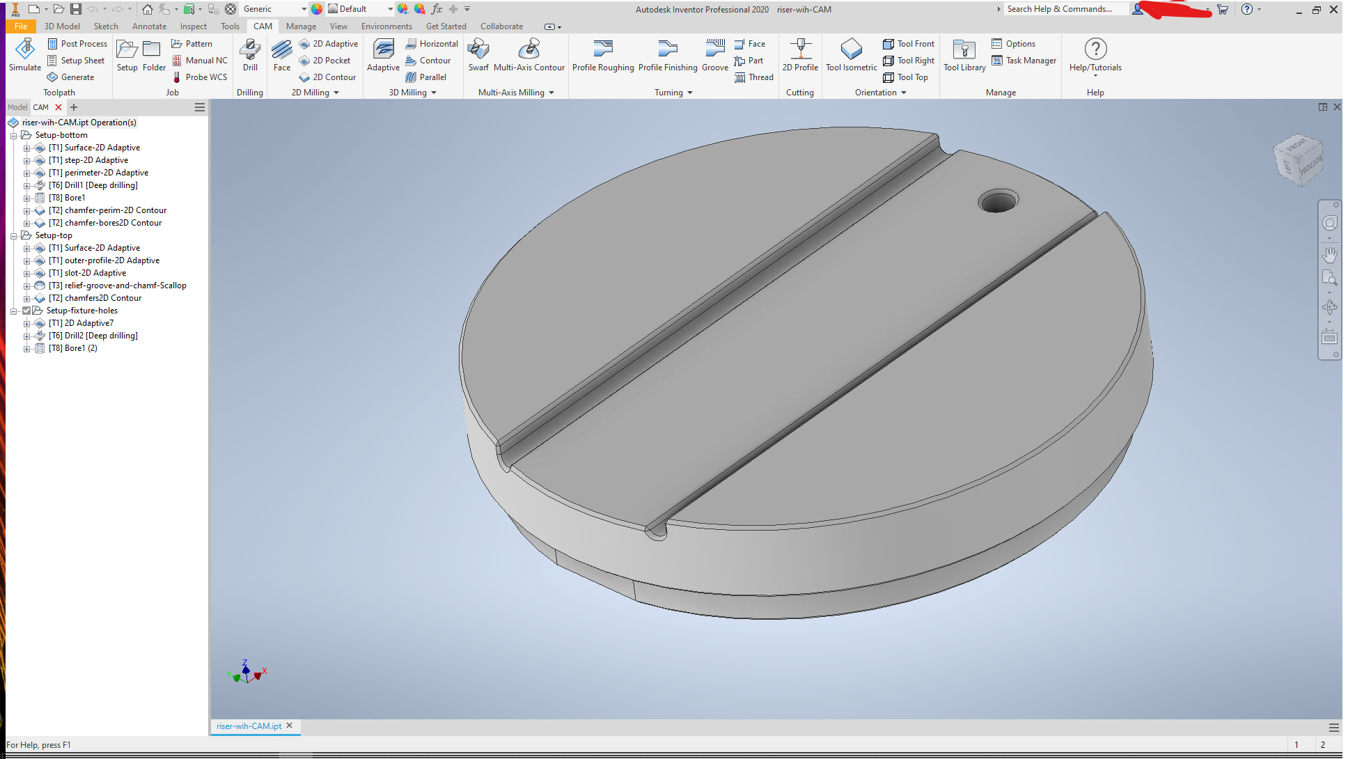
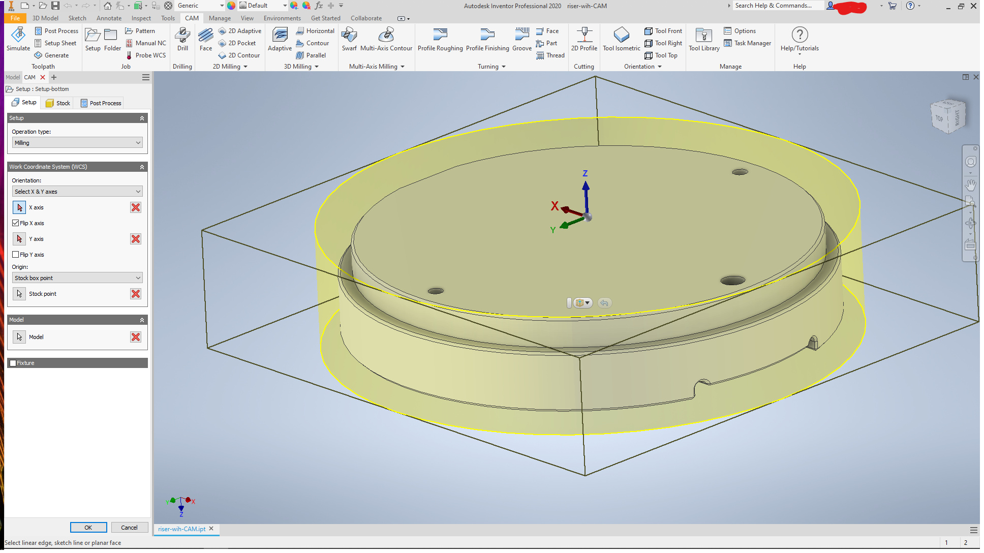
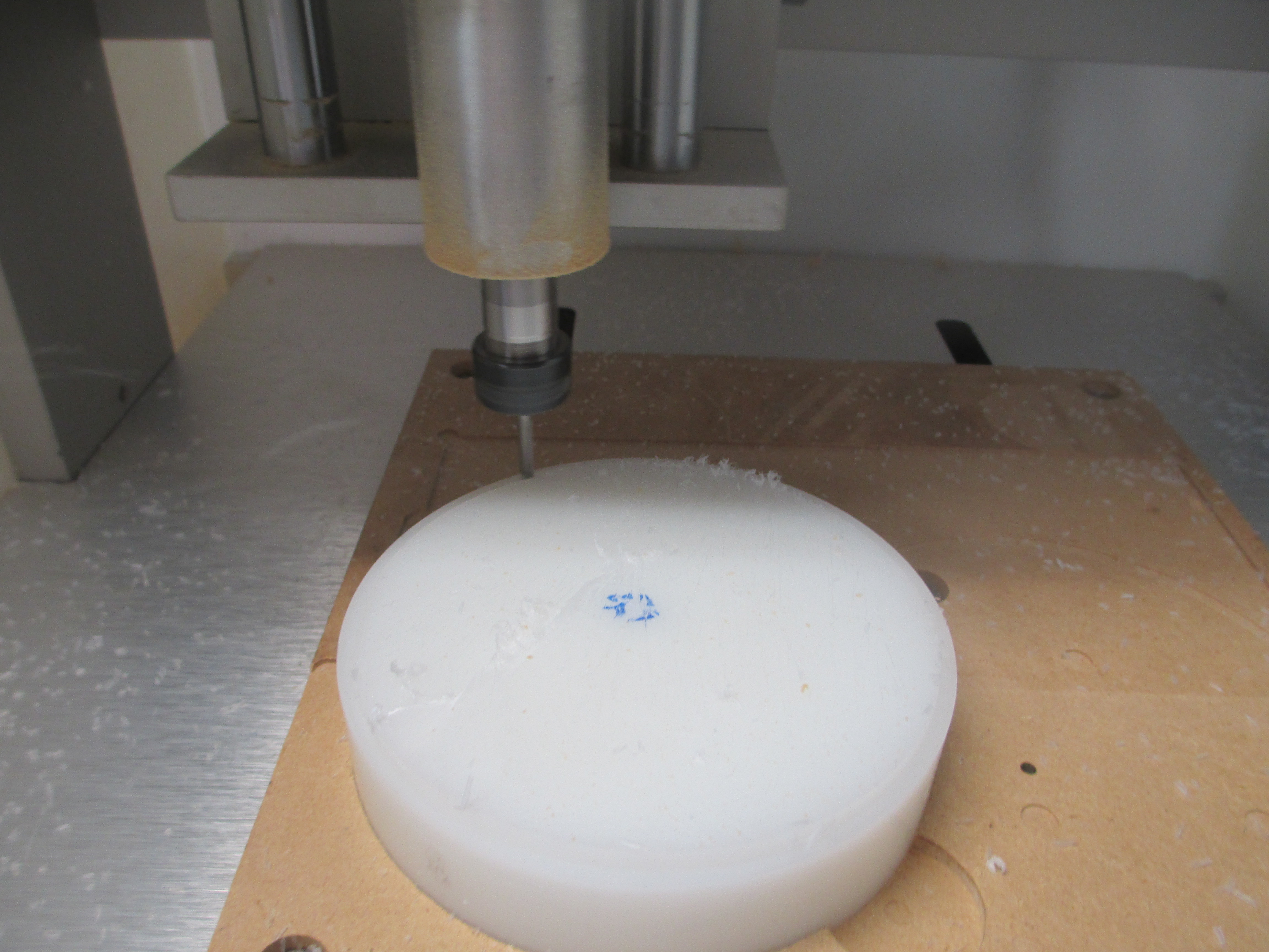
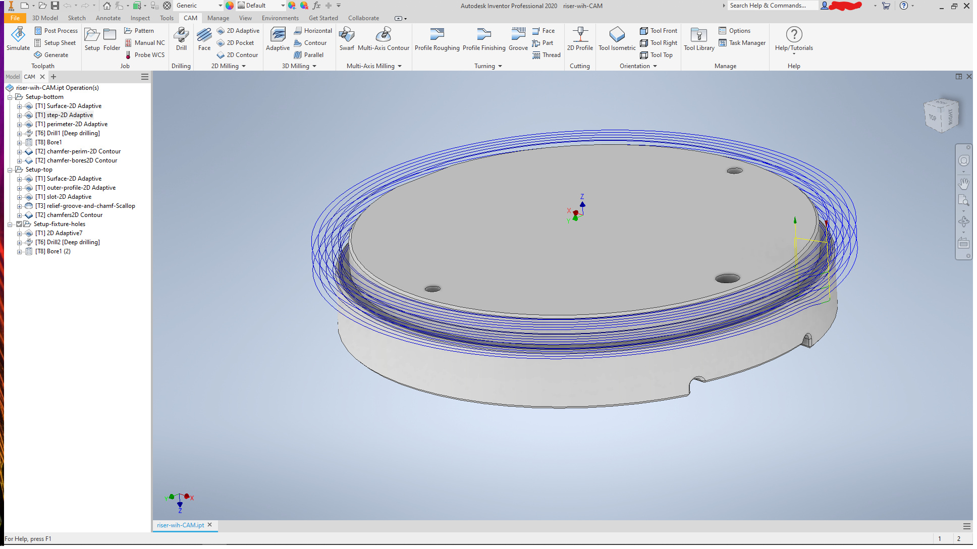
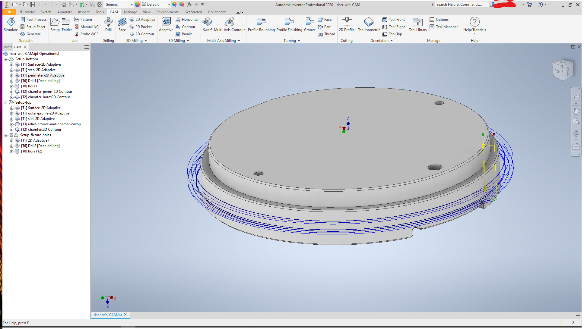
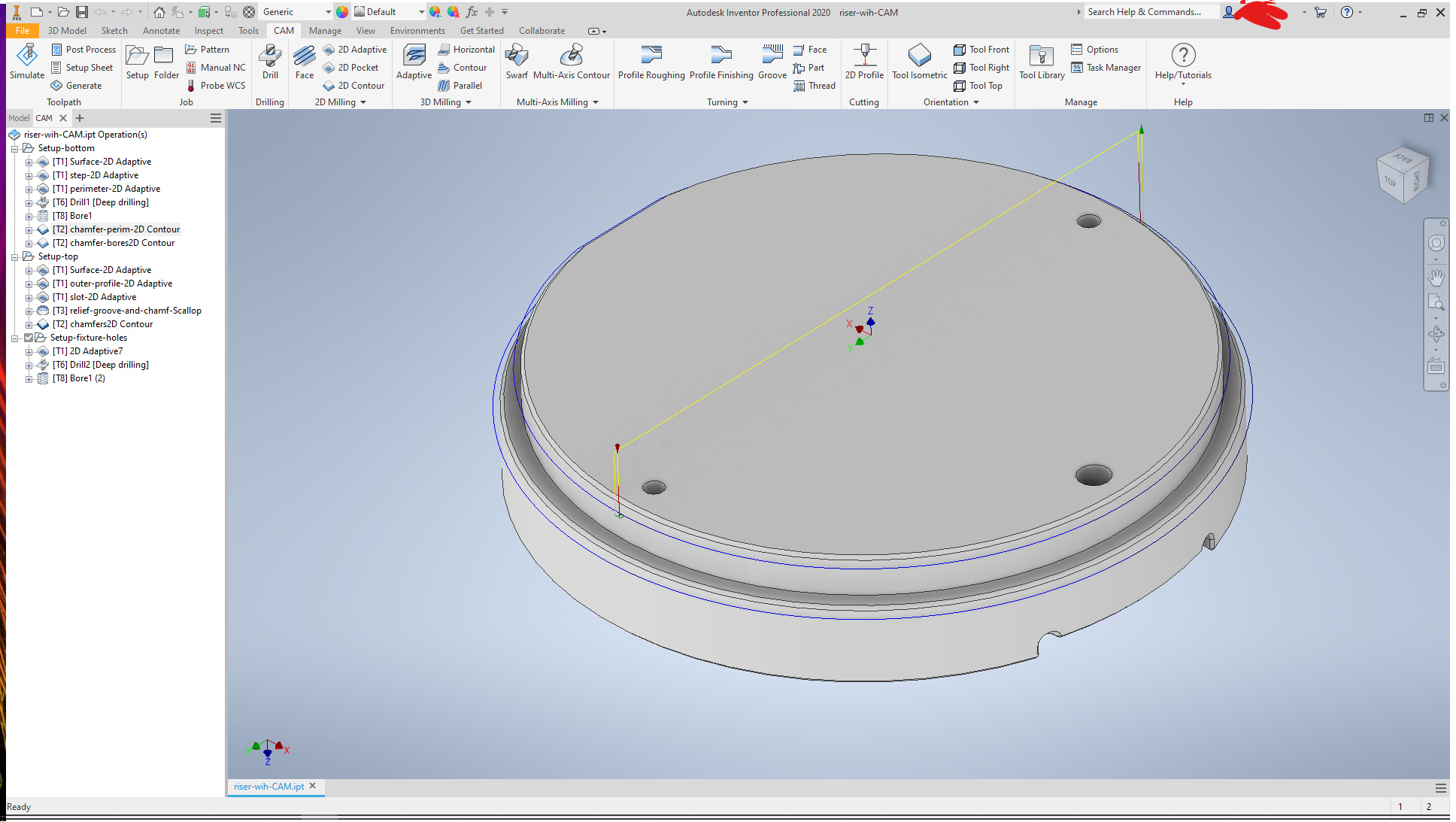
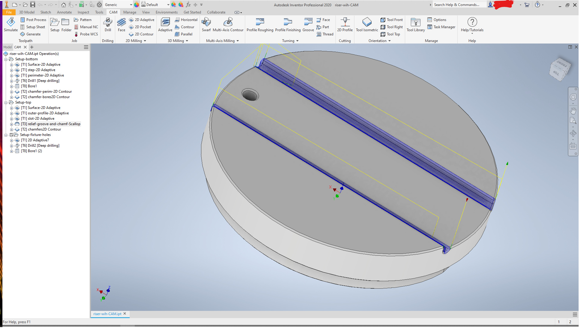
These are the CAM operations for the main model.
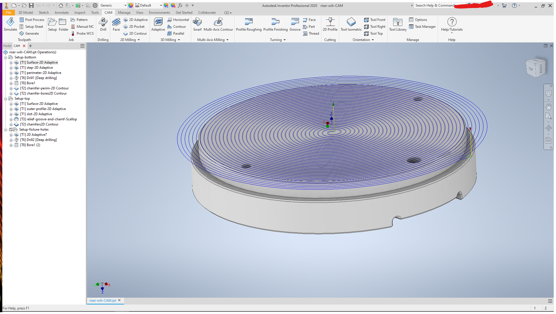
The bottom first:
The boss to fit the well plate:
Check the size
Then the lower portion of the OD
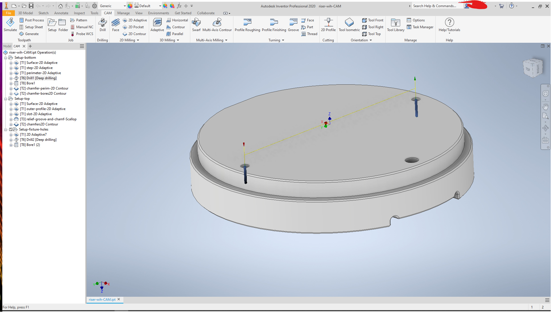
and dowel holes
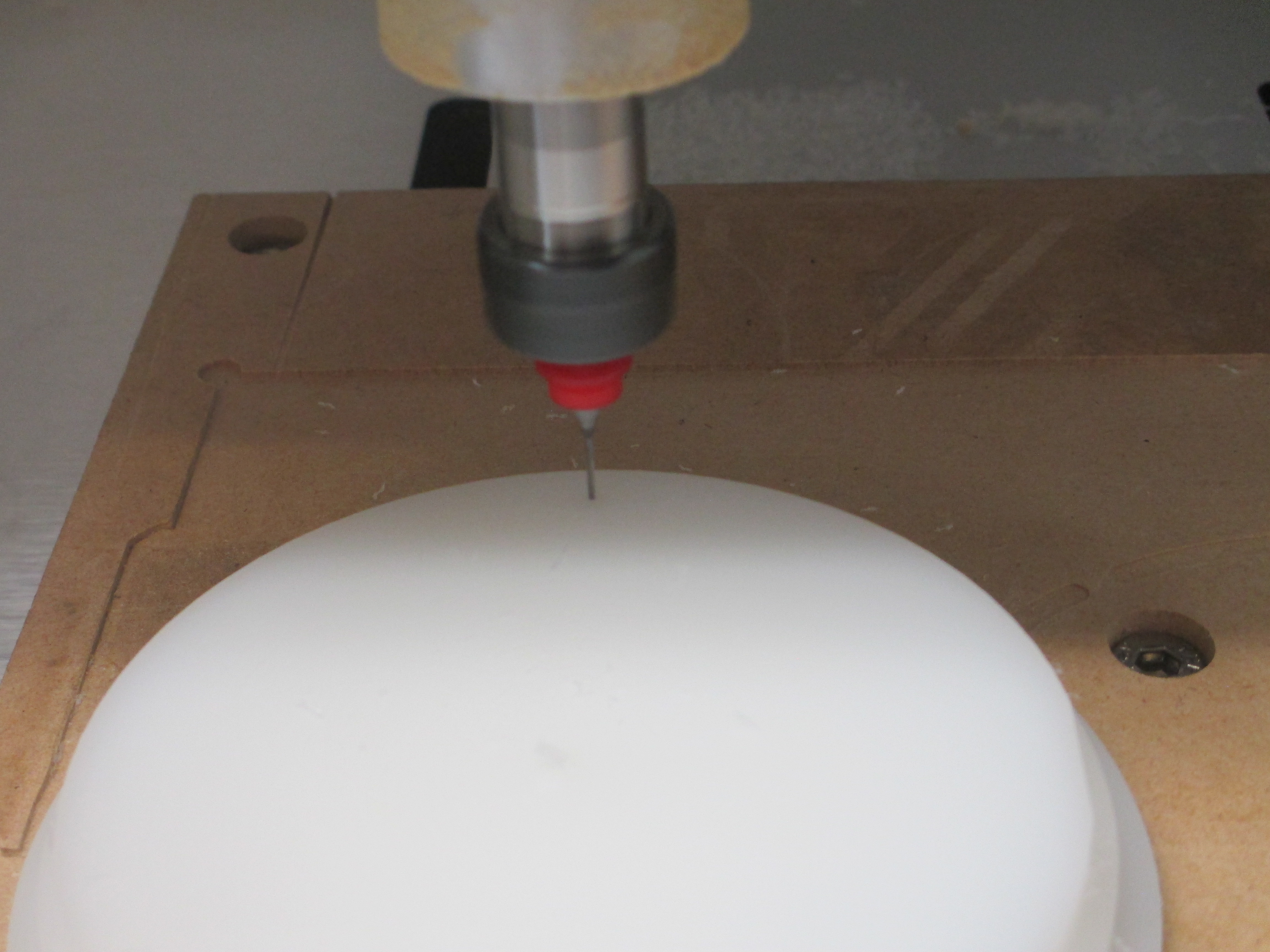
The dowel holes were piolted with a small drill to provide clearance for the endmill to cylindrical bore. Technically not needed since the bore is less than about 1.8 times the endmill size and it will essentially be a helical entry, but the bore is so small relative to the endmill that the center may not clear properly, so a pilot reduced tool lossage and work lossage. The time for all of this is seconds.
And then chamfers
Do the dowels fit?
Yup.
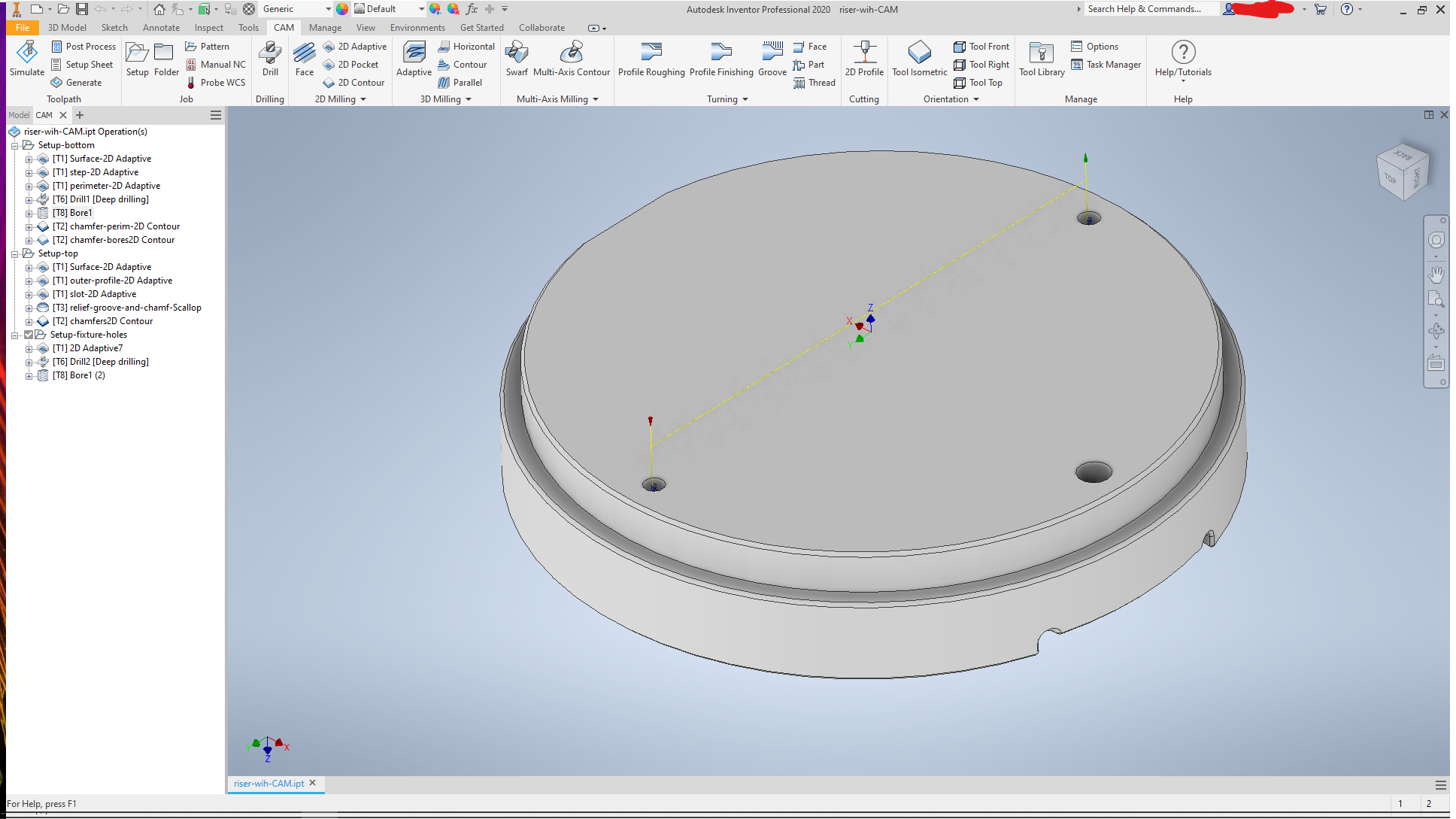
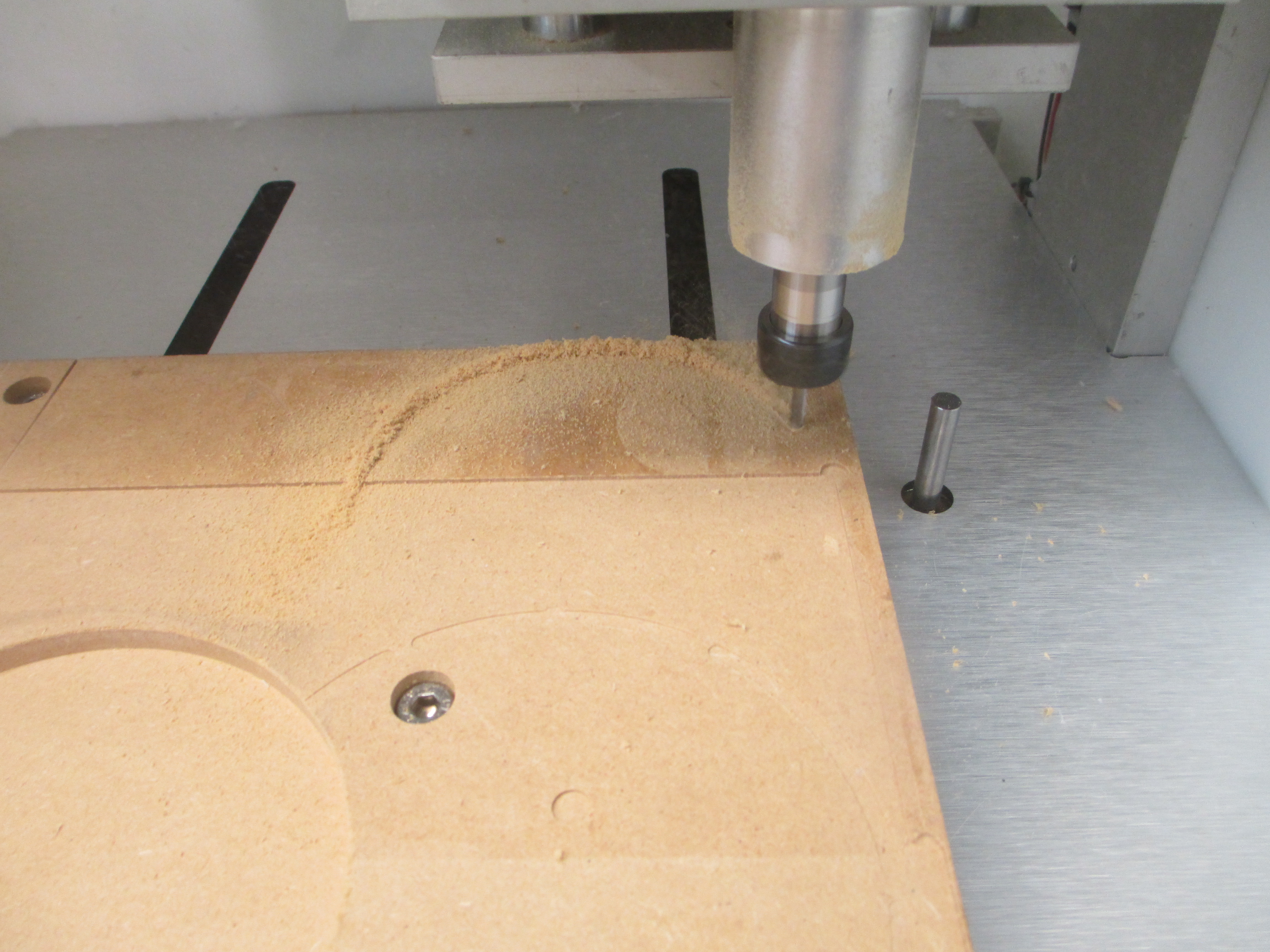
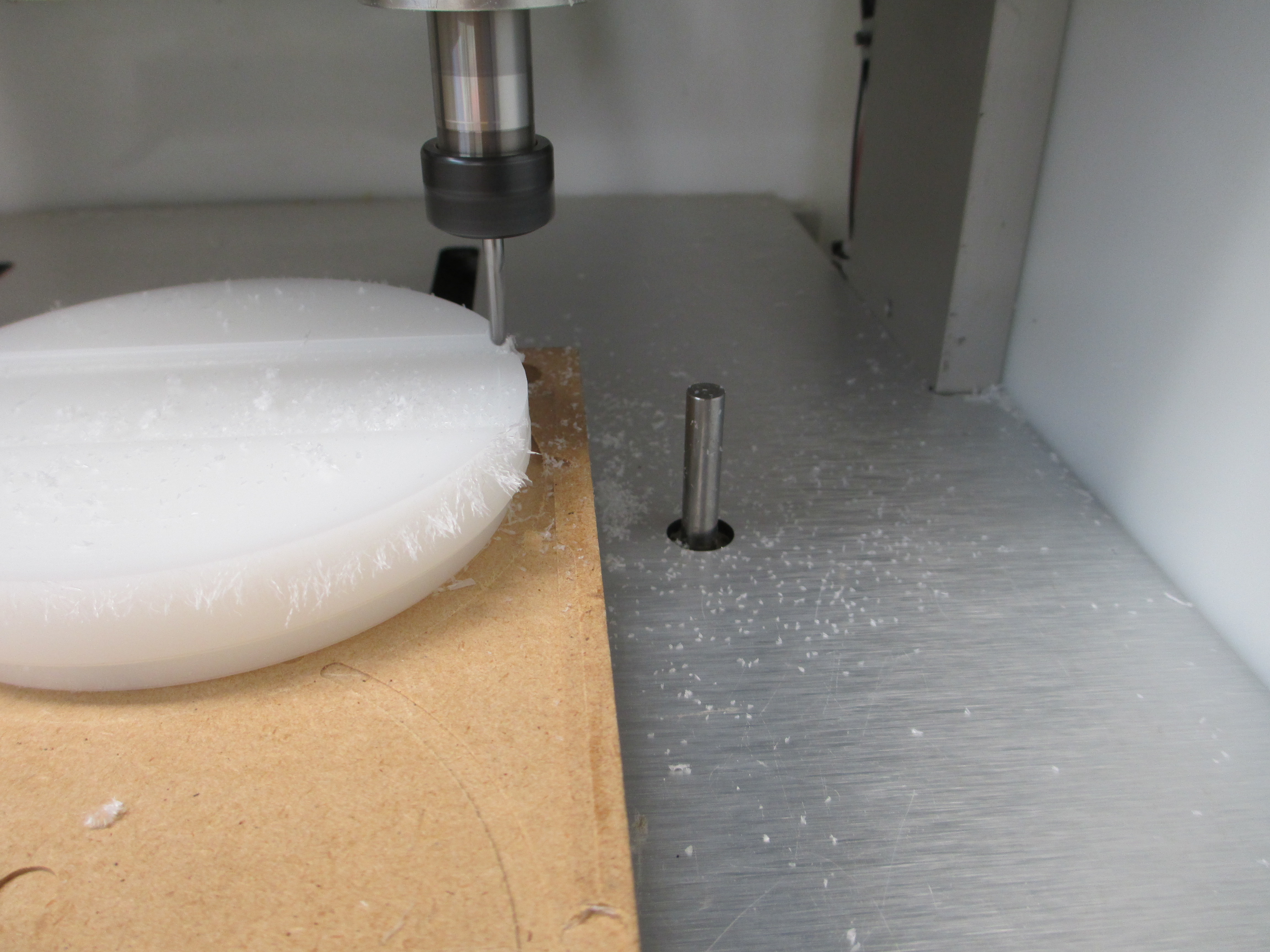
Now machine fixture points for the second setup
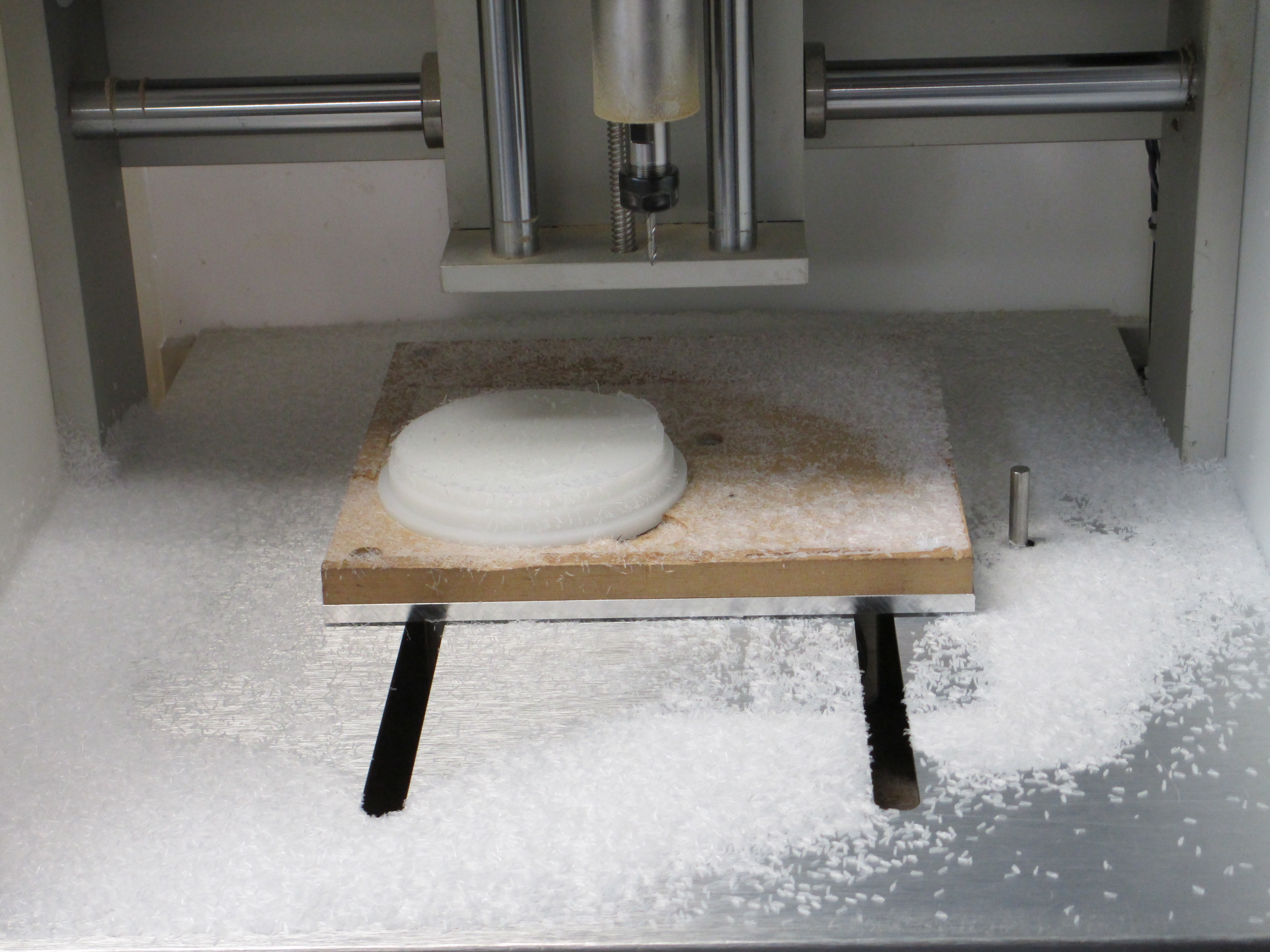
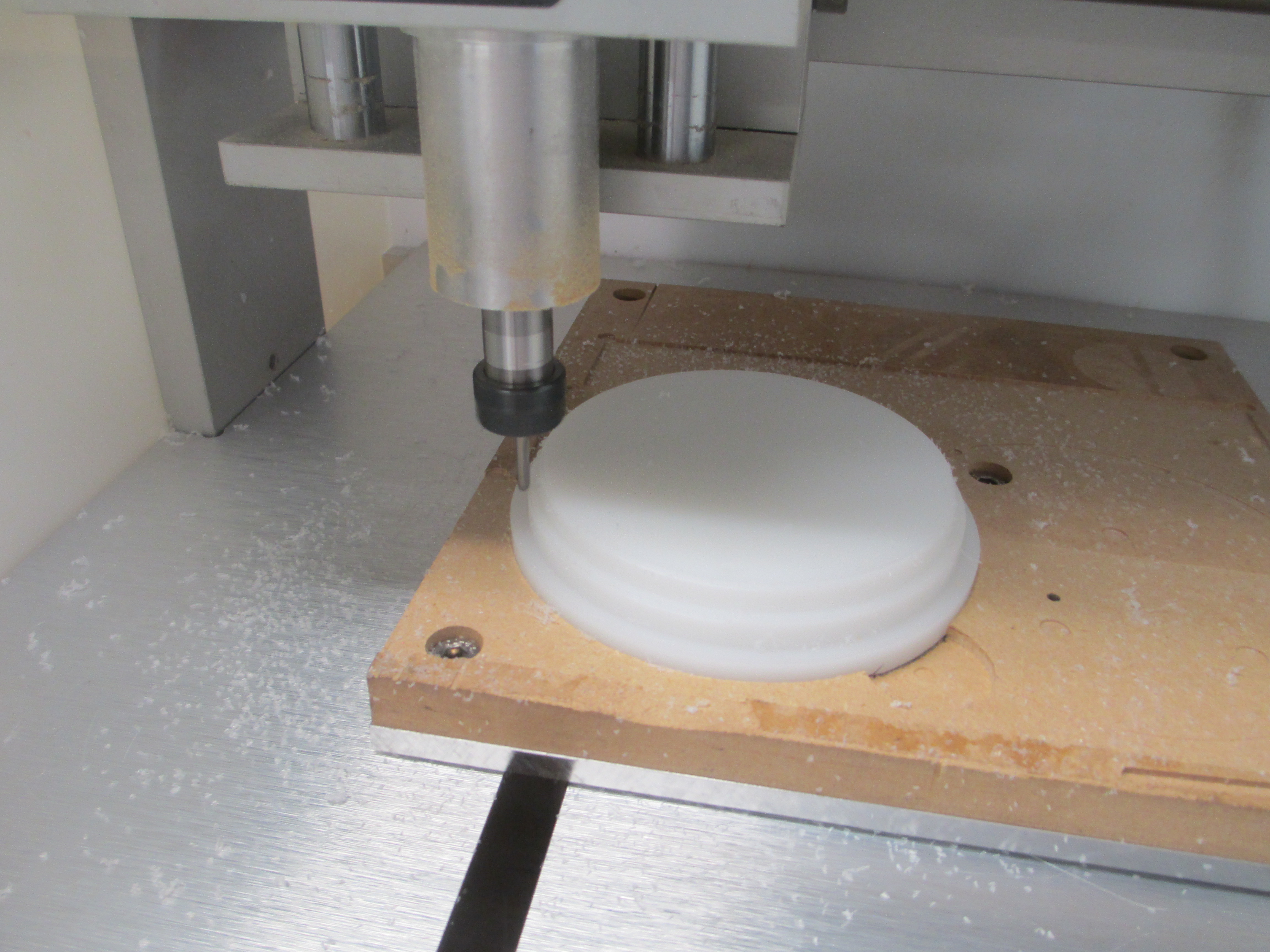
and mount it
using a strip of 3M 467MP. The dowels are tight, but there isn’t sufficient surface area to prevent the part from lifting.
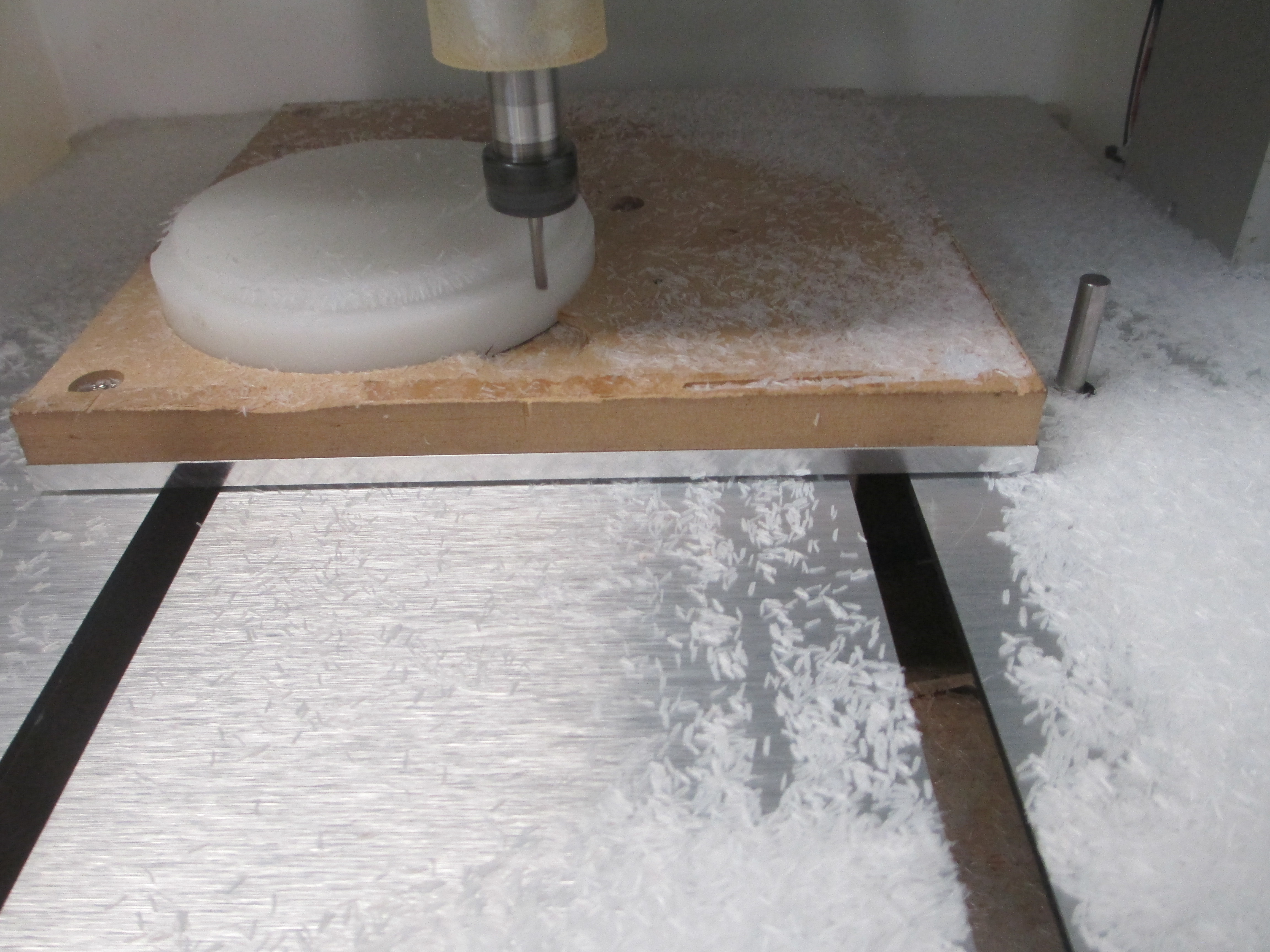
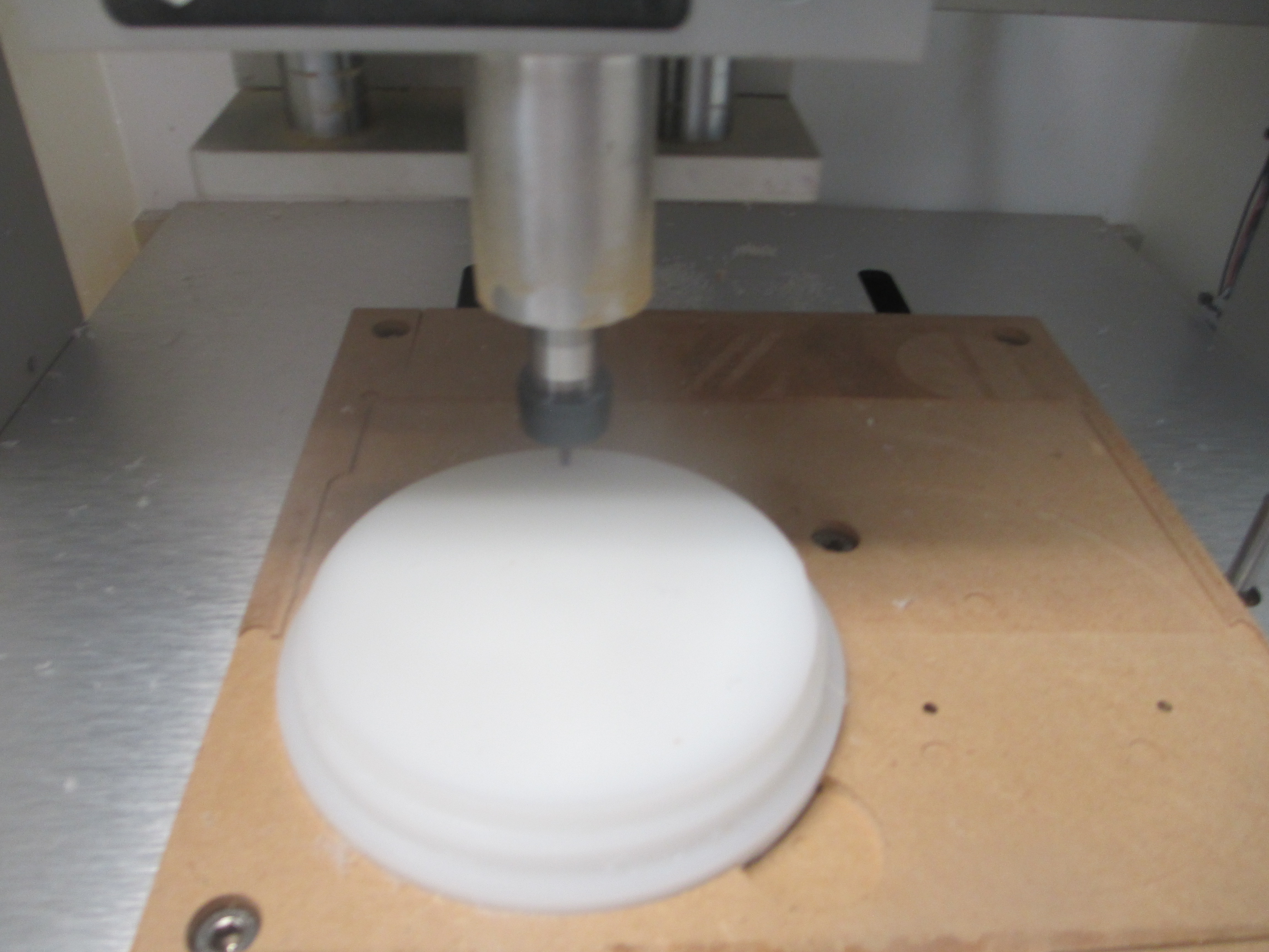
Machine the top (nothing to say here. Much the same, except for the relief grooves)
Final chamfer being put on
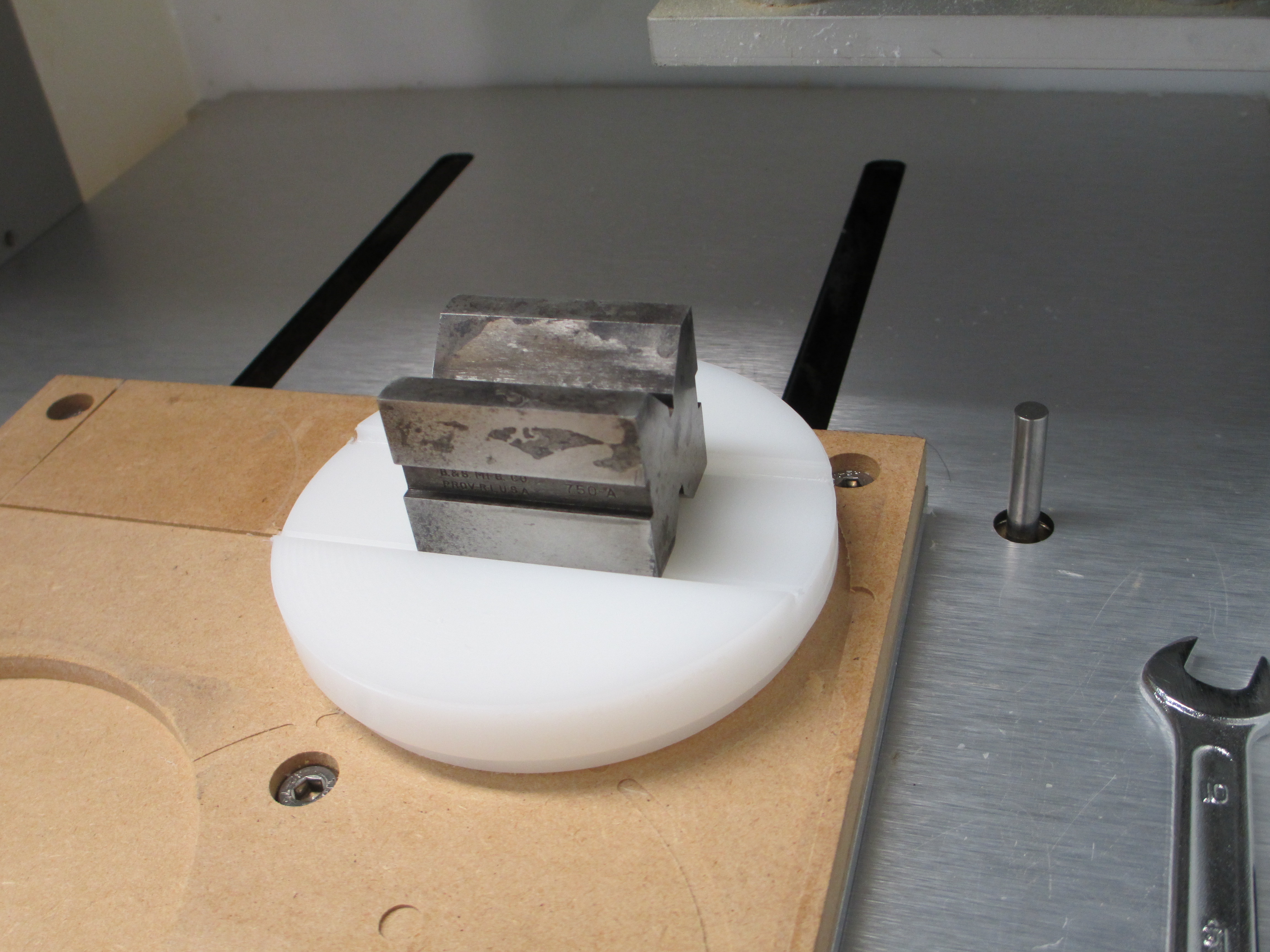
And test fit the vee block after a stiff toothbrush cleanup
As I had already run a test part, the side play is <0.05mm, which is what I wanted. The block is free to slide endwise, but has a little drag. The first test piece took two or three shots to get it sized right.
The model is attached. [riser-with-CAM-inventor.zip|attachment] should anyone want it. (upload://q2TYe0P4NEAyRR5jMWMxSTUMCj7.zip) (1.9 MB) The tools used were 3.18mm flat end, 3.18mm ball end, 1.59dia ball ens, 2.38 flat end for the dowel bores, and a 1mm dia drill for piloting for the bores.
The most time consuming part was the initial pocket fit for the rough stock. The supplier cut was cocked and rough, and my cut for the blank wasn’t any better using a handheld power hacksaw. I’ll shut up and top revising now. My shop manager just jumped in my lap (a 9YO black cat) and wants fusses.
Ok we now have acrylic/polycarbonate, HDPE, and Delrin covered.
Final day before the deadline!
Hi all,
As mentioned in another thread, I tried a wooden v-inlay in acrylic. Didn’t think I would finish today, but here’s my second entry:
Settings for the acrylic were like in my other project:
Then the male part of the inlay with plywood attached with wood glue, sawed and sanded off.
The base was cut from two sides to fit the LED strip and the acrylic sheet.
 But parallel lines are boring, anyway.
The files:
christian_plug.c2d (739.4 KB) LED_base.c2d (83.7 KB) christian.c2d (1.1 MB)
Whew - sliding in at the last moment. Did not start this project with the competition in mind, but the milling plastics competition has brought out some really interesting “make things work” entries so I figured I would throw mine in as well.
So I have an application for remote sensing and data collection in a marine environment. The intention is to capture forces, acceleration, and angles for human powered watercraft aka rowing shells, sprint canoes, surfskis, outrigger canoes.
Requirements are:
(1) needs to adapt to multiple environments (on hull, on oar, on paddle)
(2) needs to be waterproof! Somewhere around IP-68+
(3) needs to float - just in case
(4) needs to have a viewport to see LED status
(5) needs to be easily (but not too easily!) removable! for data download and recharge
(6) housing needs to pass bluetooth - no aluminum shell!
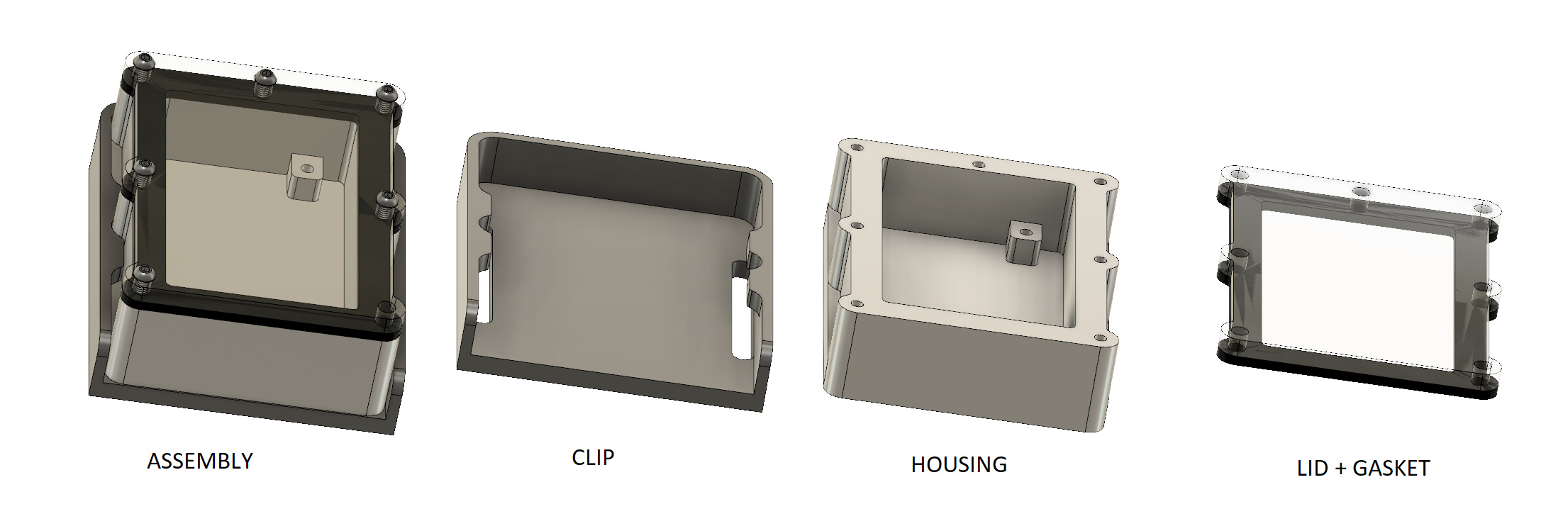
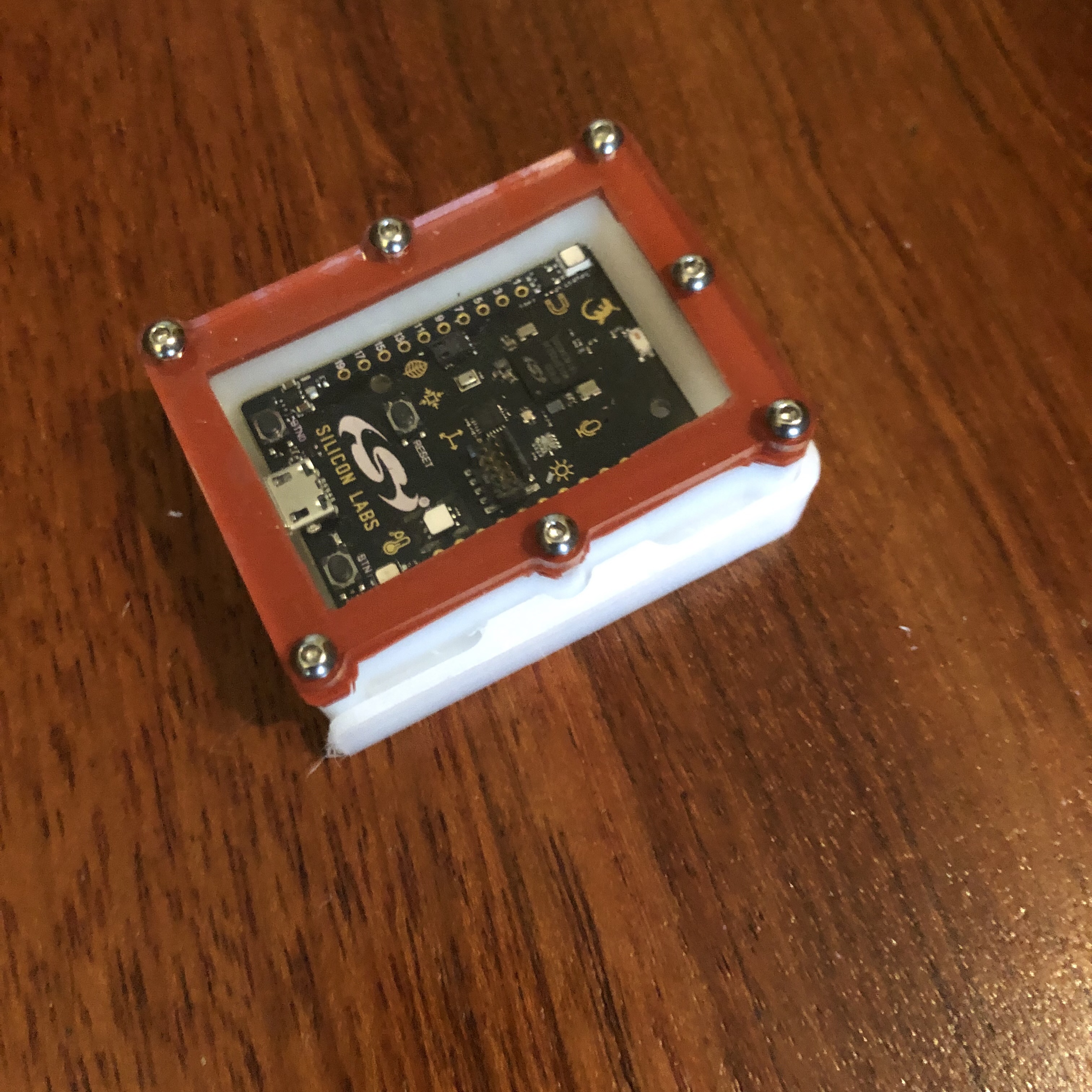
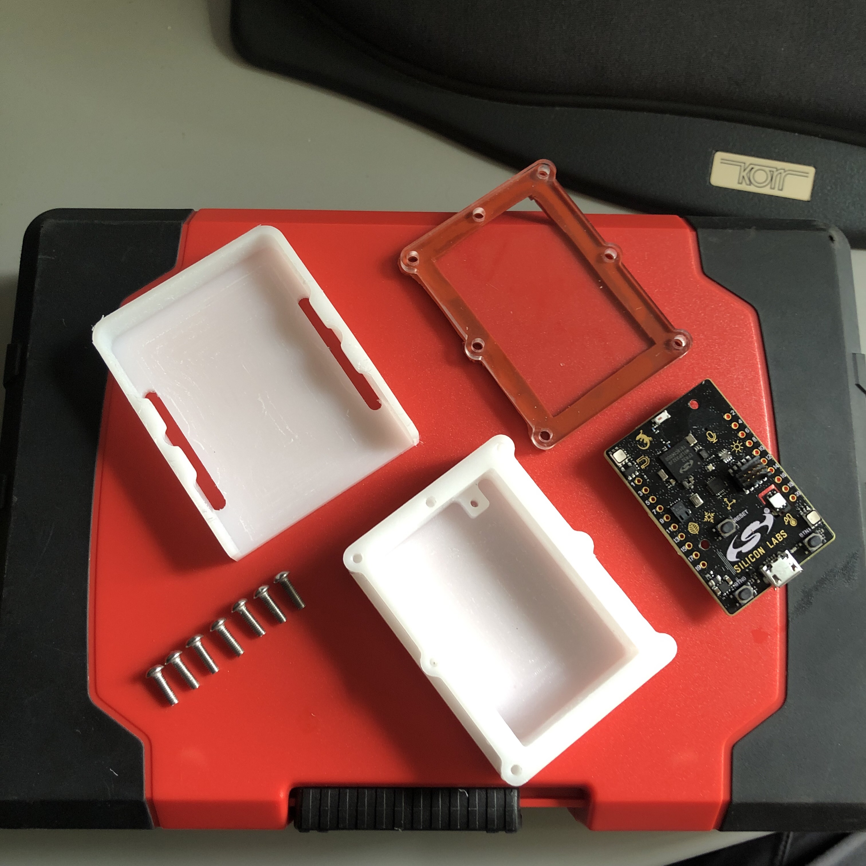
I had a Thunderboard Sense 2 development kit lying about to use for proof of concept so off to Fusion 360 we go for a housing to protect it.
a HDPE housing, a silicone gasket, a cast acrylic lid, and a UHMW mounting clip.
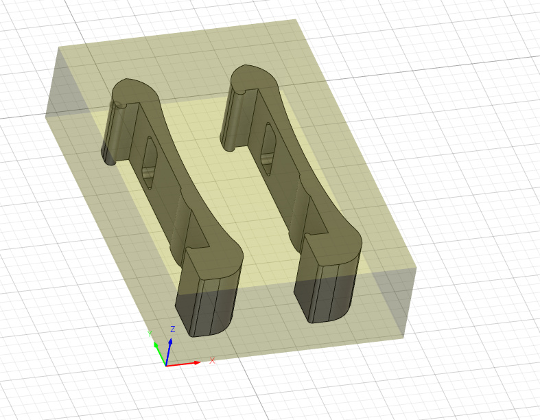
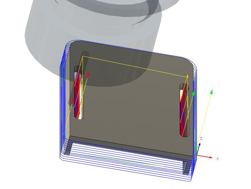
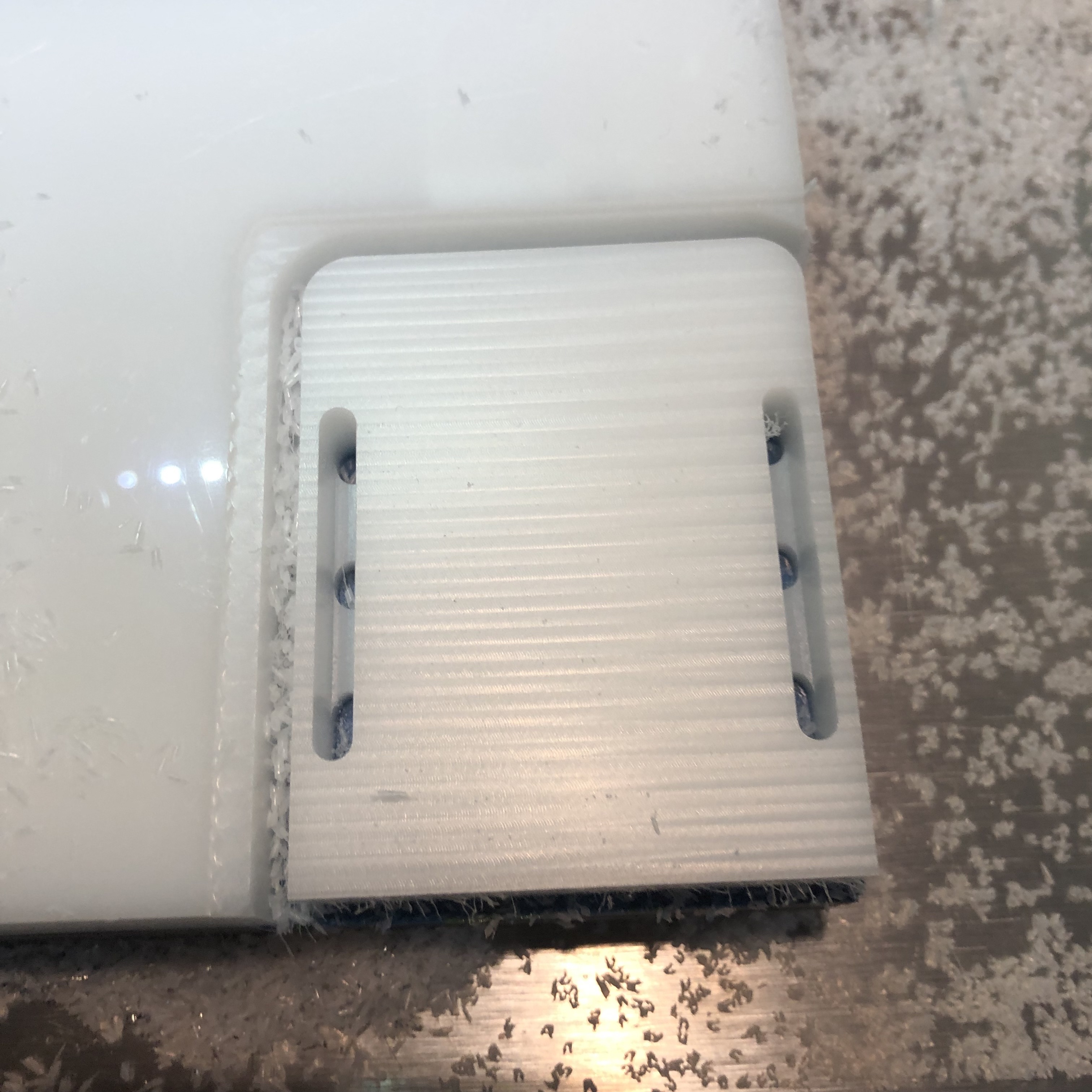
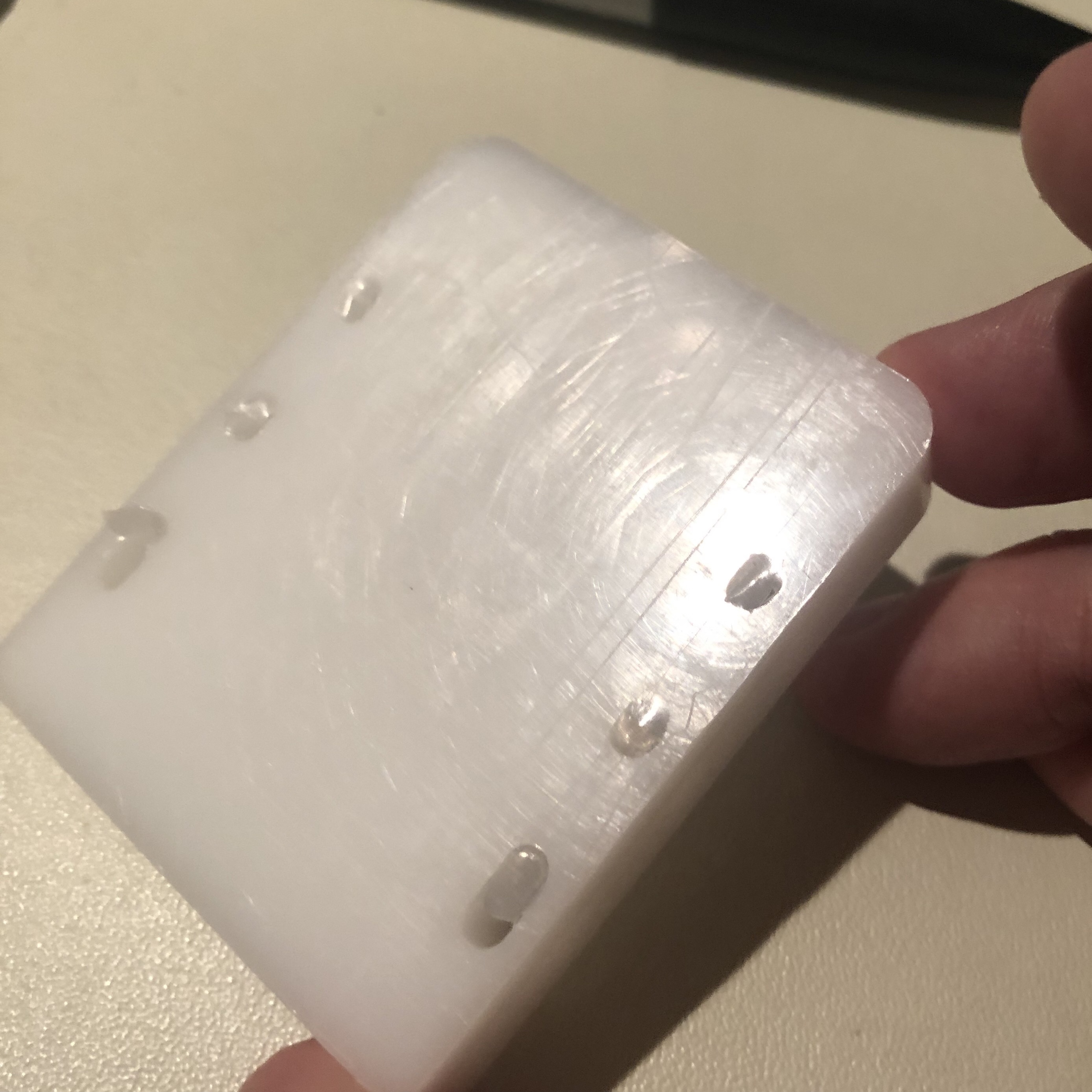
Designing the housing was quite straightforward other than some deep small holes for the M1.5 screws but designing a clip that would retain the housing that could release AND be machinable took a bit of pondering and fooling around. The clip will remain attached to the boat/oar/paddle and the housing would be removable. Eventually I settled on a slide-in style clip that would have a flexture to allow the retaining tabs to hold the housing in place. Machining could be done from the bottom of the clip to create the overhang and the flexture at the same time.
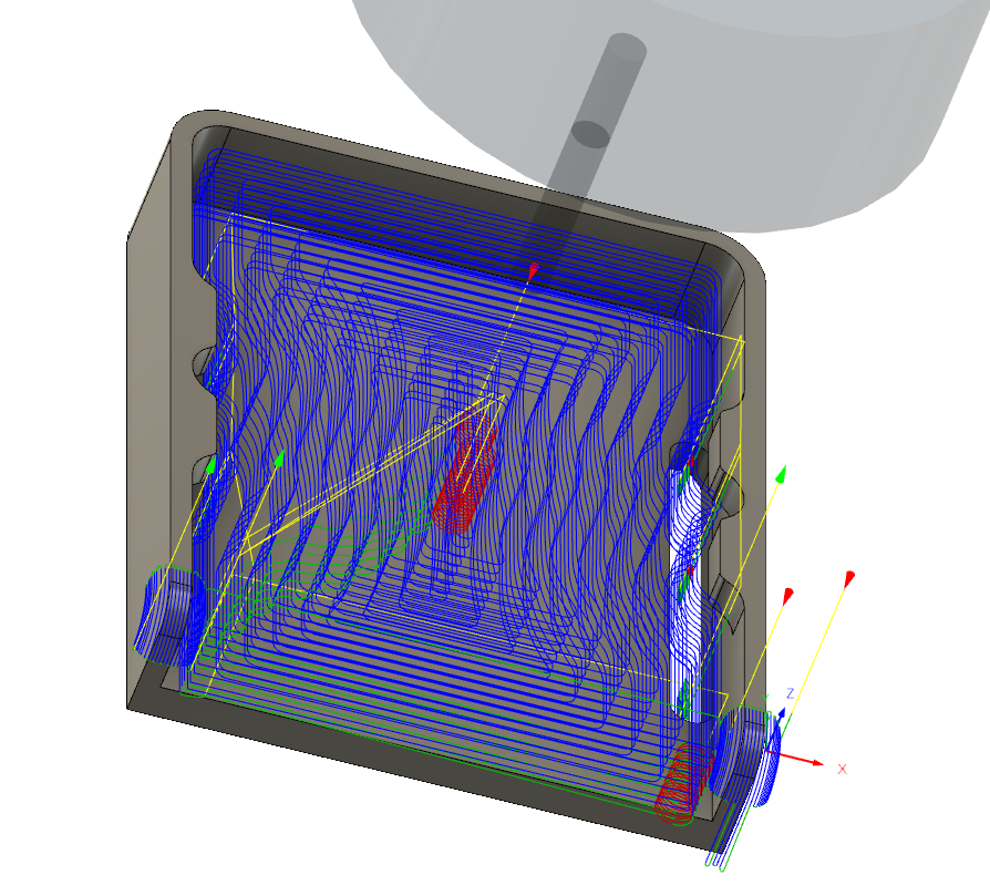
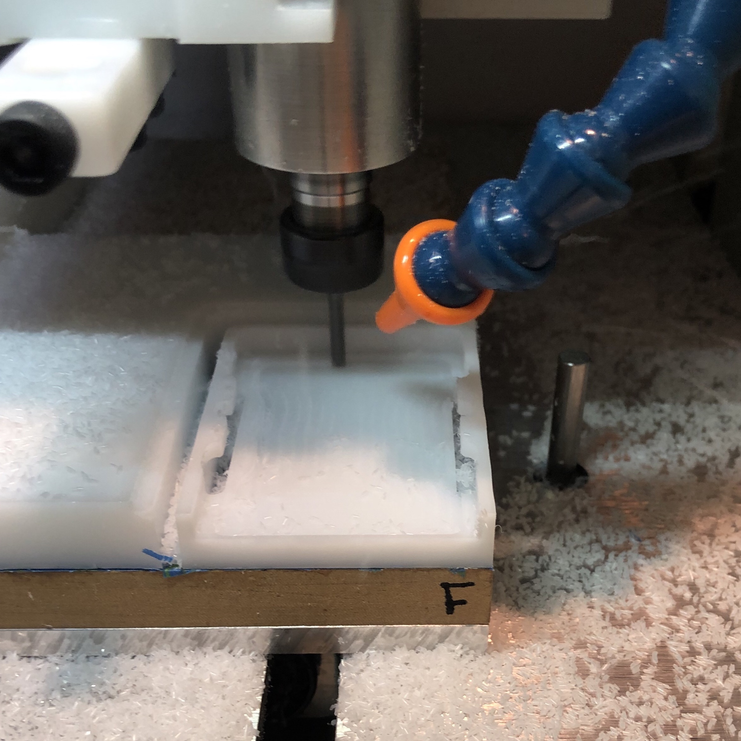
Once that was done it could be flipped and the inside of the clip could be pocketed out.
CAD done, off to machining. Again housing and lid pretty straight forward operations. I looked into machining the silicone gasket but it looked like I would have to freeze it with liquid nitrogen or some such equivalent so back to the craft knife and punches it was.
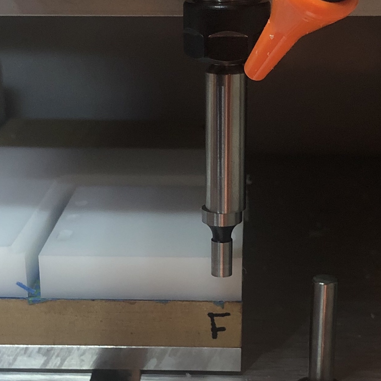
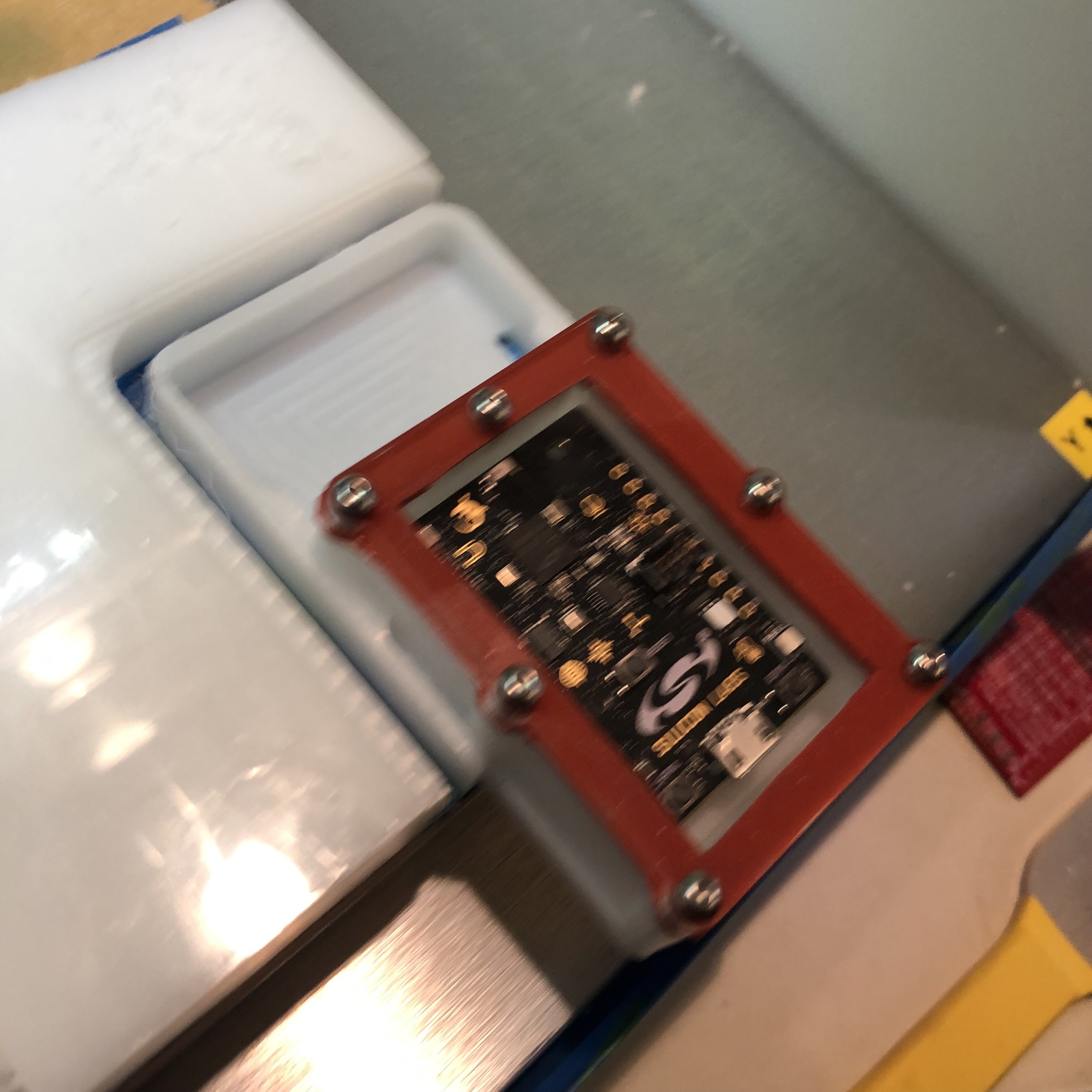
Machining the clip was the interesting bit (and also overlapped the competition) so I took photos.
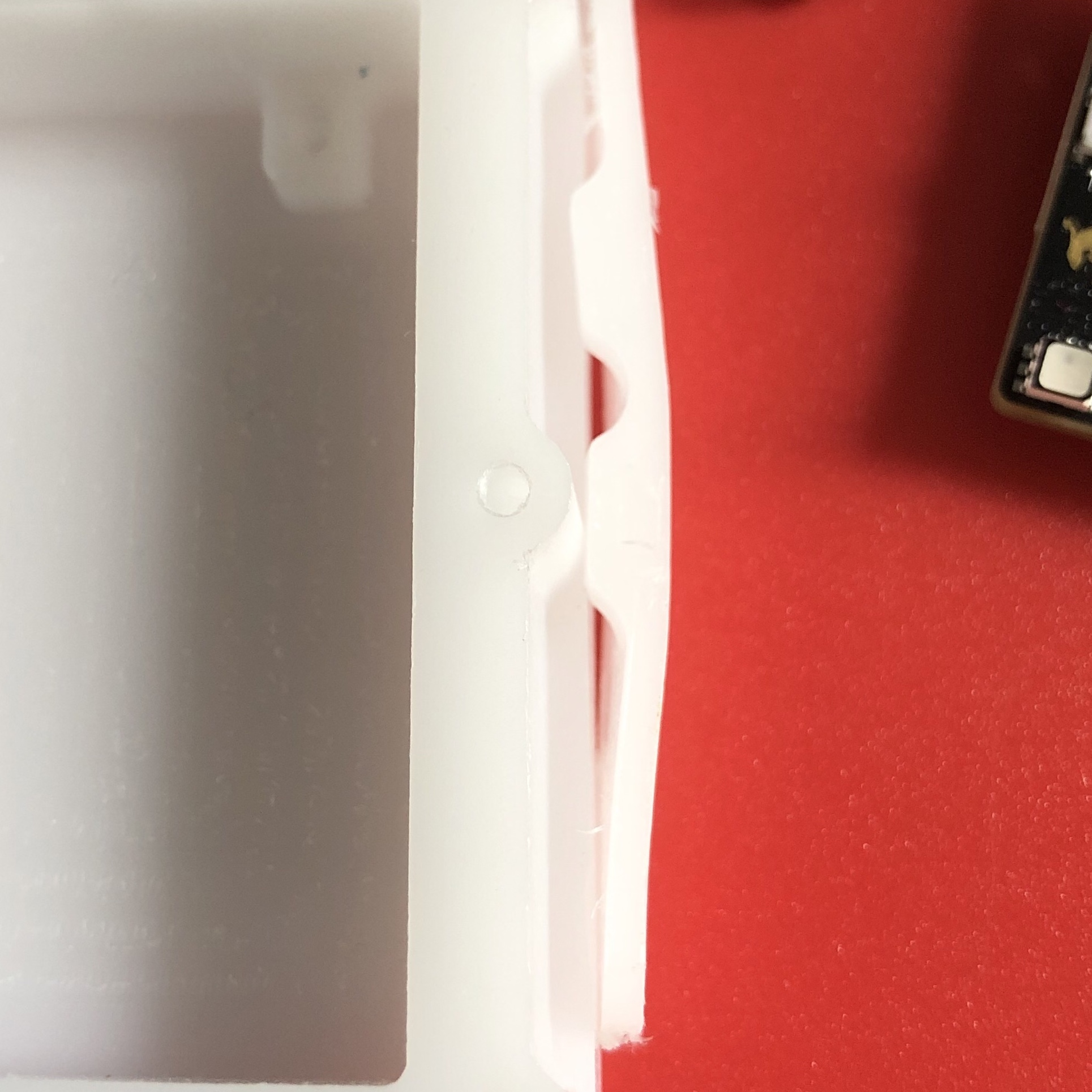
Clip bottom complete
A little onion skin
Flipped, taped down, and edge finding the X and Y edges
Tabs looking OK!
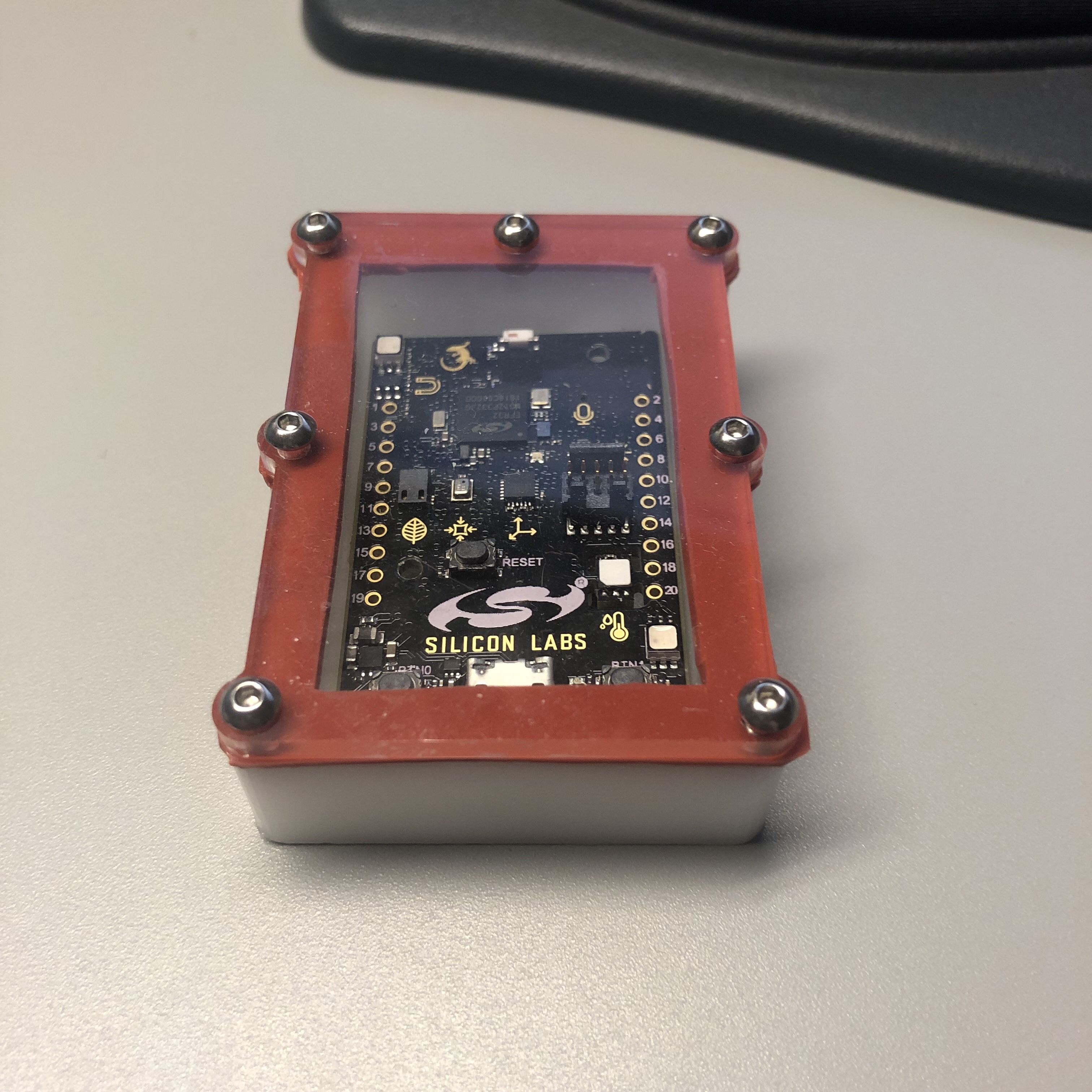
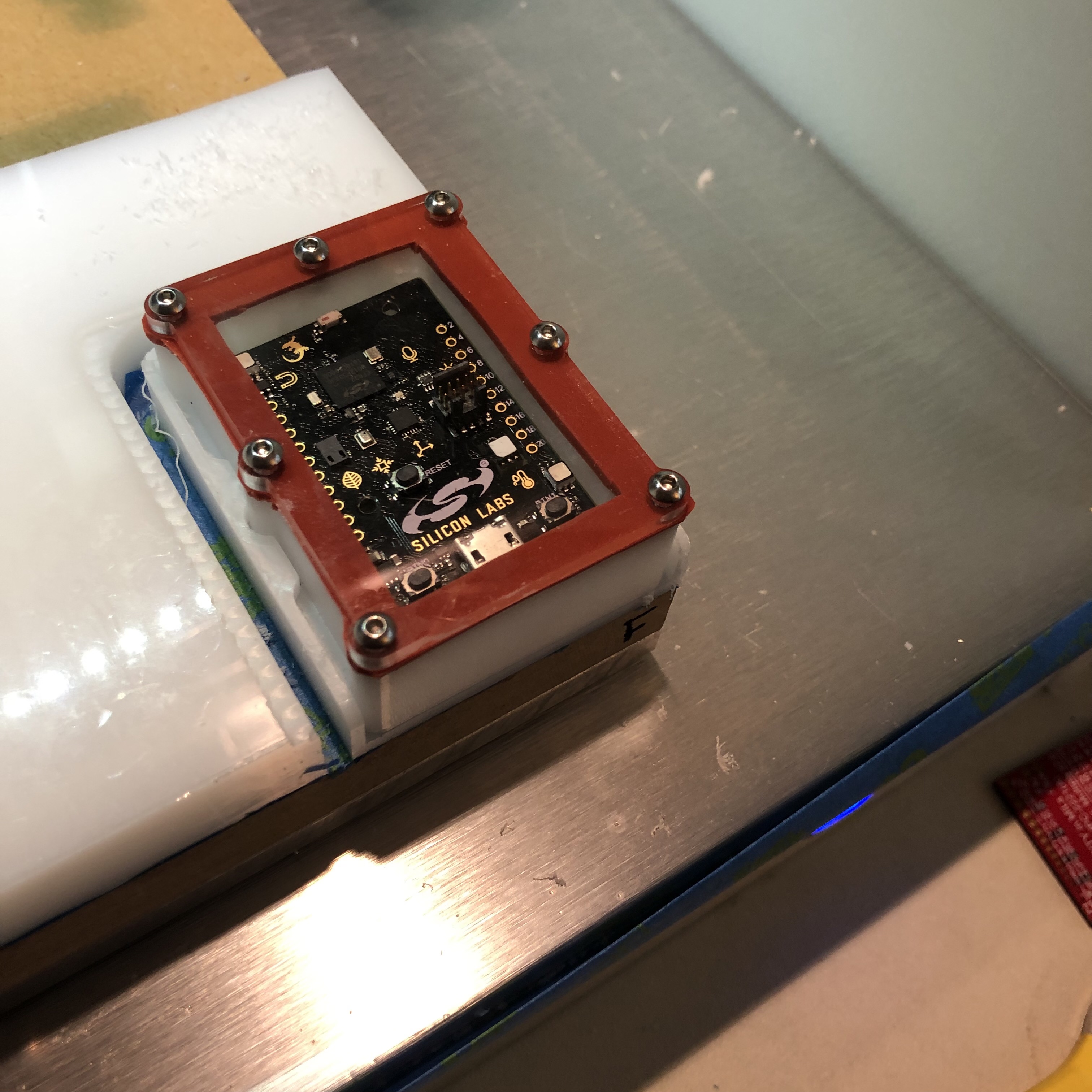
Test fit before removal
It fits!
Mid clip-in
In mid-flex
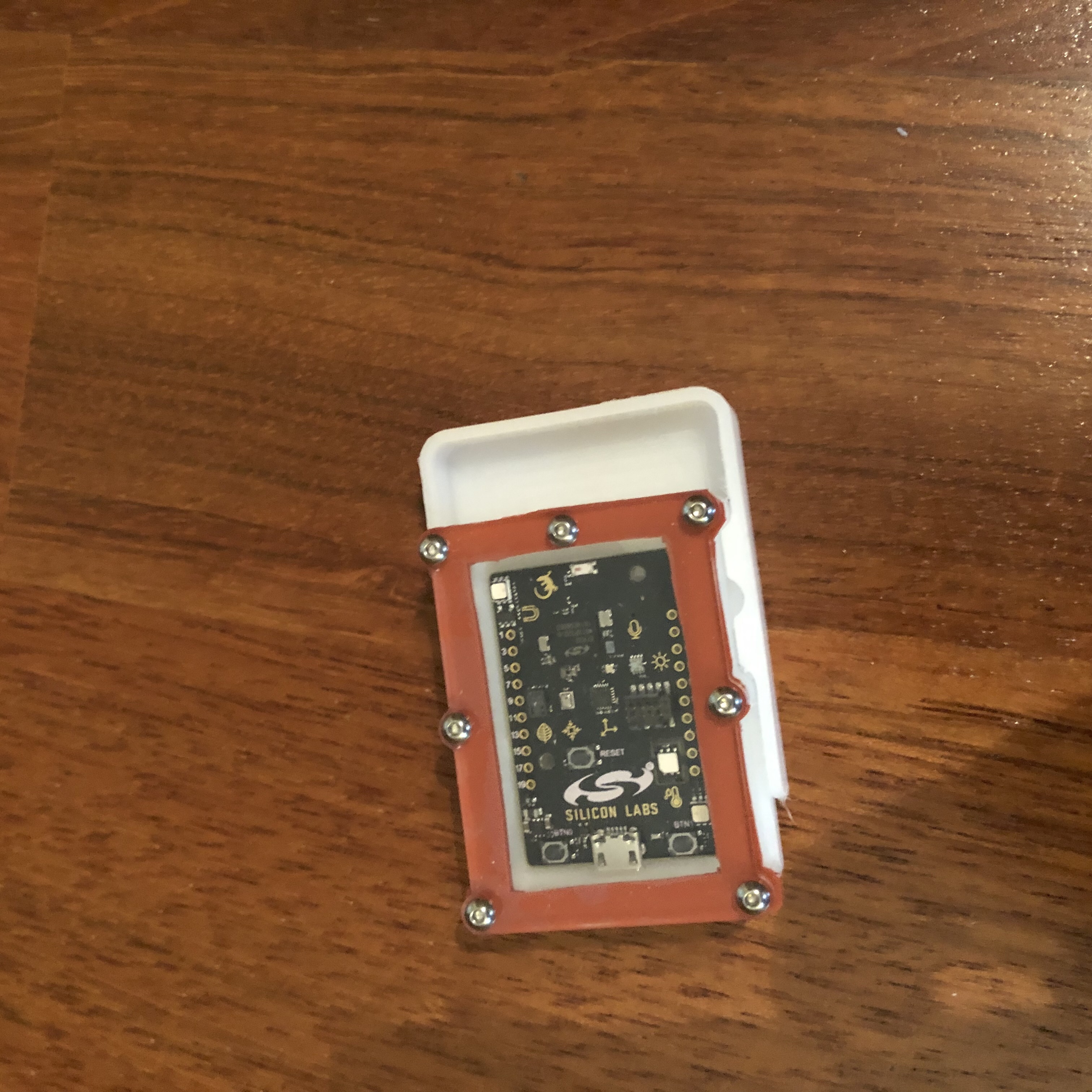
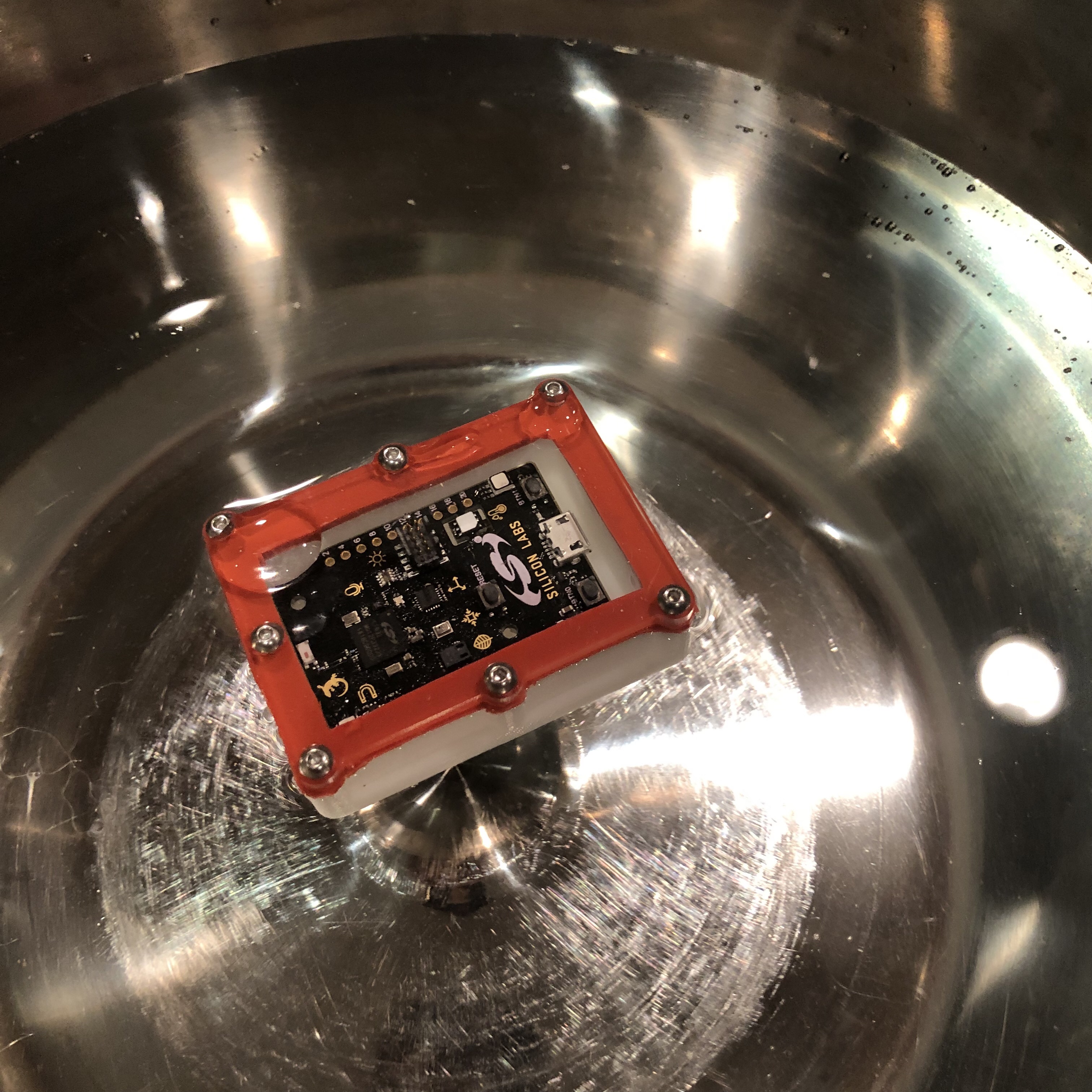
And some preliminary testing of course
It floats!
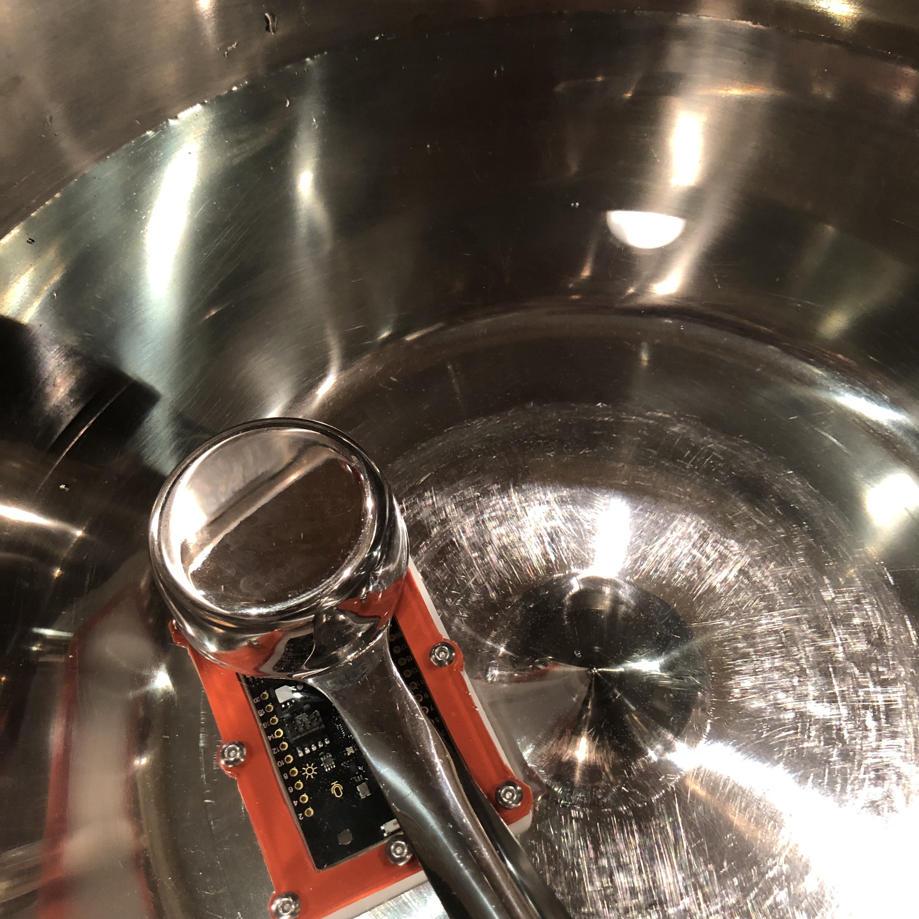
Submersion test
Design files up on CutRocket! I hope someone finds the case/clip/flexture ideas useful!
Entry #3 (Butterfly Lamp)
My 5yo daughter didn’t want to be left out of the “new room” stuff, so she requested a rainbow lamp. As soon as I got the LED “neon” lights in from China, I started working on a design. She then changed her mind and wanted a butterfly lamp. Because she’s pretty much in charge around here, I told her that would be no problem.
I went full plastic on this one. The lamp is made of white expanded PVC (0.75” & 0.5”), translucent light diffusing 3mm cast acrylic, and cellophane sheets.
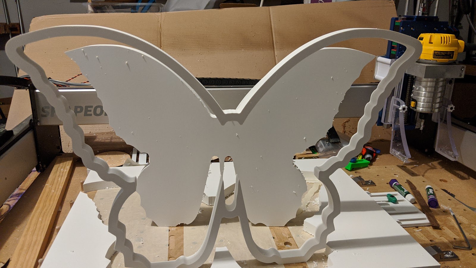
First, the final result:
Started with some options for the design (to run by the bosses) in Inkscape.
Made sure the bottom was flattened and everything was symmetrical. Ended up deciding against the antennae because they would ultimately be broken (by kids, not during machining). Boss didn’t approve of that decision, so I gave her a compromise that I knew she’d like.
Pulled the SVG into Fusion for the final CAD, but mostly just the CAM. Inkscape was the design workhorse on this one.
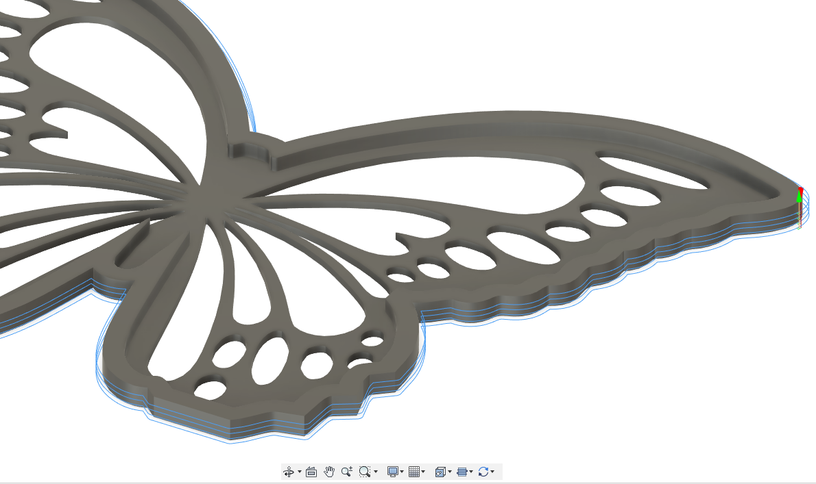
Front was made from a sheet of ½” PVC. I pocketed the inside to a depth of 8mm using an adaptive toolpath.
¼” Single Flute
Feed: 2500mm/min (could definitely do 3500)
Speed: Dewalt on two-ish
DOC: Full 8mm
Followed that with contours to clean the inner perimeter, cut the holes, and cut the part out.
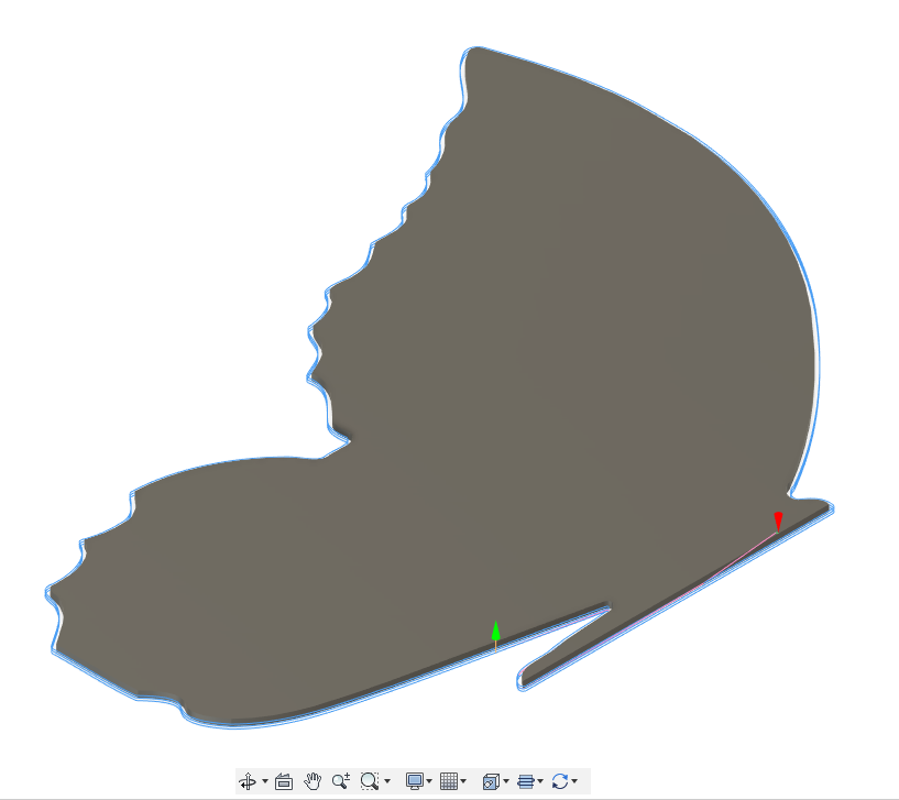
The middle piece is ¾” PVC just to add thickness, so it is just an “outline”.
I was a little nervous about this middle part becoming really flexible, and I tried out the “Thin Wall” feature in Fusion 360. Basically, it alternates machining inside and outside profiles to keep the forces balanced….kinda cool. It’s really meant for machining super thin metal features, but definitely something that I hope to remember.
The back is also ¾” PVC. This is similar to the front without the holes.
Cut full depth (15mm) with an adaptive toolpath at 3000mm/min…Love watching it cut PVC!
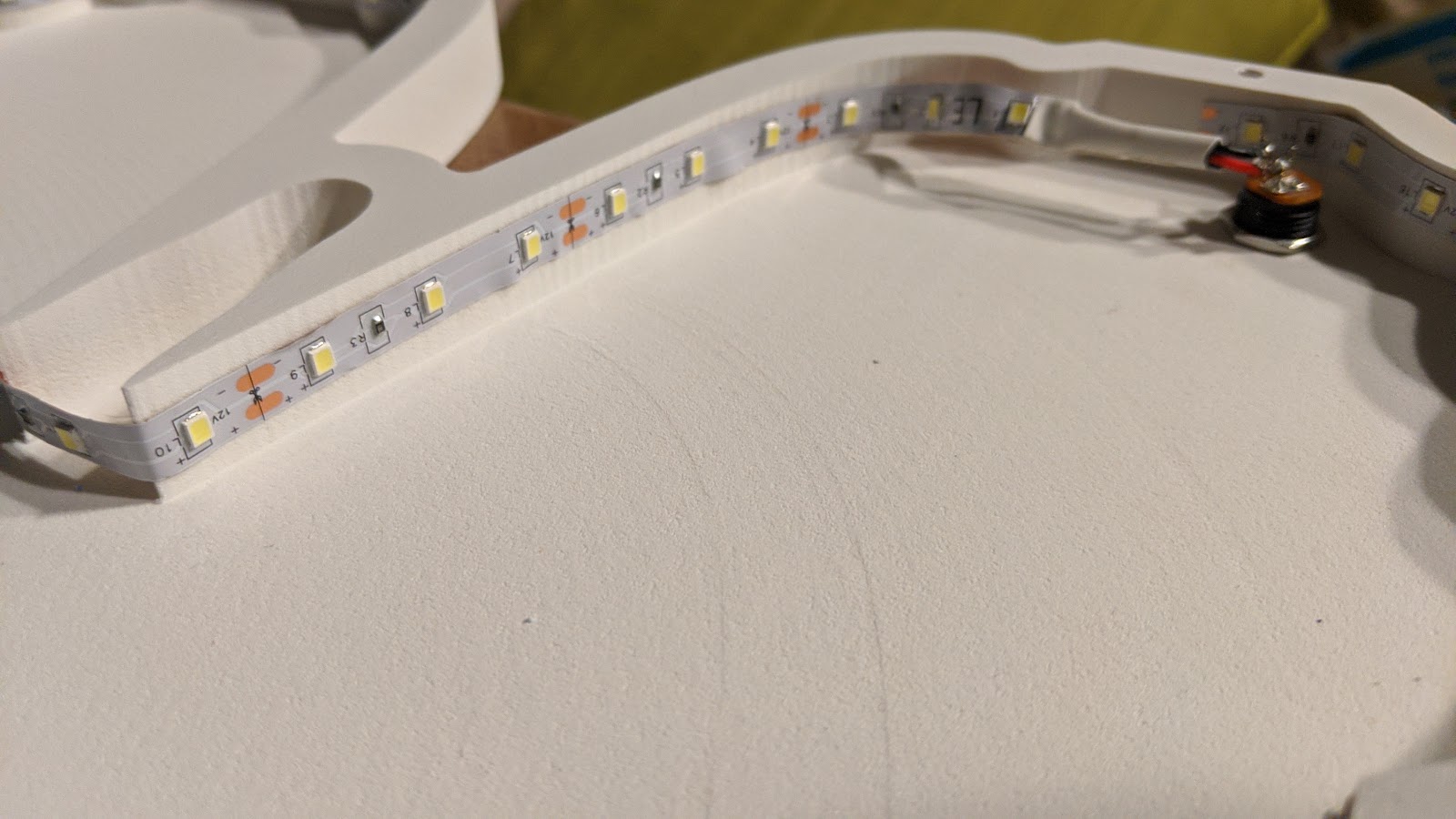
Used an external, inline switch on this one, so I just soldered the bright white led strip straight to a barrel connector and ran them around the perimeter.
After that, I cut the acrylic using the same method I used in the other entries. I cut the halves separately because of a changed plan on trying to add the cellophane. Cast acrylic cuts really well.
⅛” single flute upcut endmill (cheap one)
Feedrate: 3210 mm/min
Plunge: 888 mm/min
DOC: 1mm
The HARD part:
To make the openings different colors, I used super thin cellophane sheets. This part made me sweat. It’s like doing a complex glue-up with fast adhesive and tissue paper.
I used 3M spray adhesive (Super 77), and it was basically a mess, but I got better as I went on and it looks good from the outside!
You can see the holes in the previous pic. I used m4 screws to hold the 3 parts together and keep them aligned. I really don’t like gluing PVC together when profiles have to match…it’s too slippery. In hindsight, I should’ve machined some alignment holes. Clamping and drilling afterward worked well.
Some more pics of the final:
Oh…the antenna. I bought a pack of party favor headbands and let my little girl choose the ones she wanted. These were simply screwed into the appropriate spot.
She loves it!
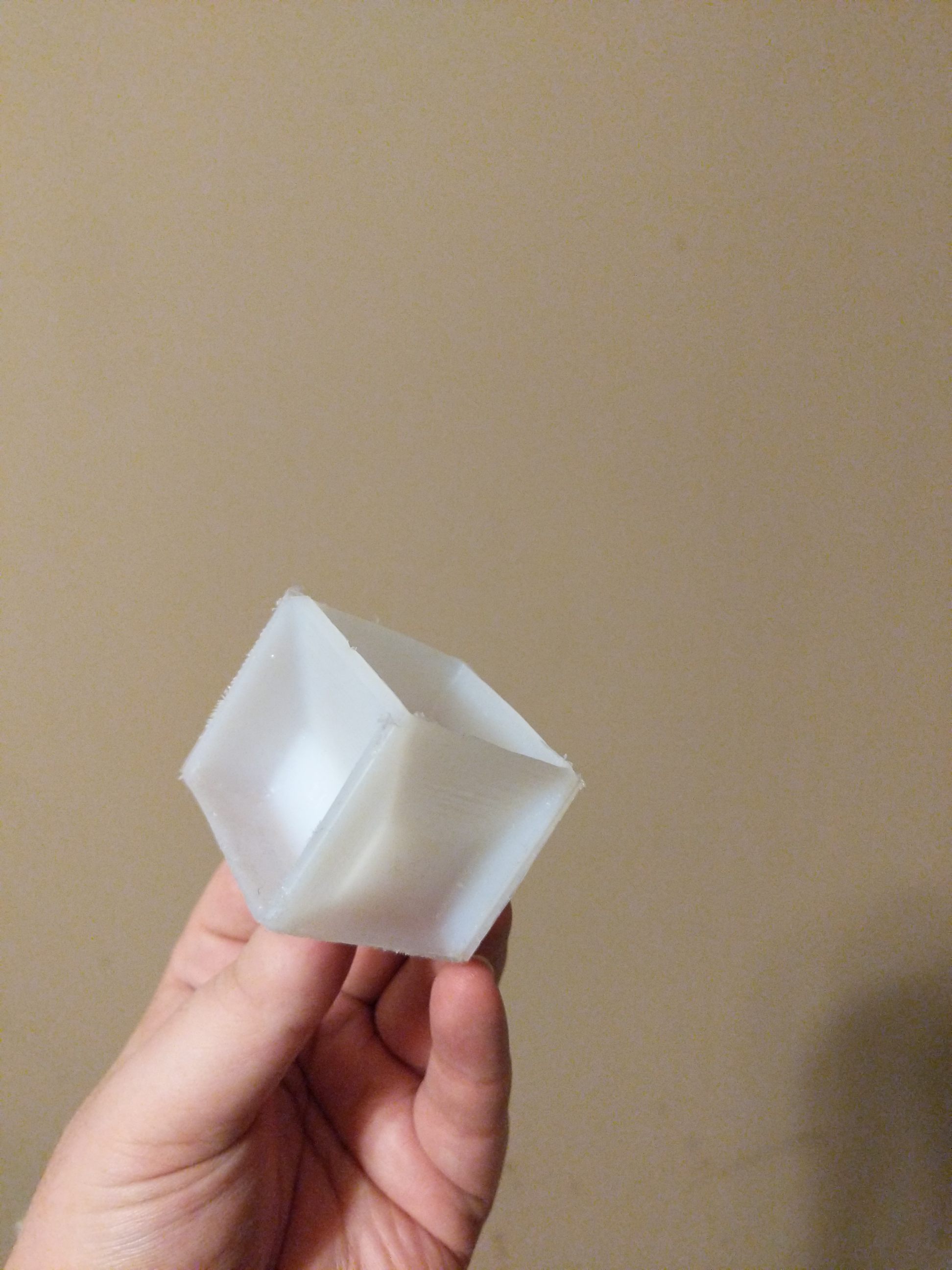
A few years ago there was a popular 3D print called a “baker’s cube” or similar.
I never made it since 3D printing wouldn’t be sanitary for food, but thought the concept really cool.
Now I’ve entered the world of CNC, I thought I’d give making one from a solid piece of UHMW a shot.
Due to material costs and size constraints, I’ve chosen the Tablespoon/Teaspoon cube for the challenge.
Started with a 2.5"x2.5"x2.5" cube of UHMW (slippery stuff). Milled it down to 1.6"x1.6"x1.6" final size so I could hold in the Nomad.
Used the Fenrus STLtoPNG to create greyscale to use in Carbide create pro.
Some careful workholding processes allowed the cube to be flipped without losing the WCS.
First trial shown below. I’m staying up way to late again to finish the show piece. I’ll follow up with Cut rocket files as well.
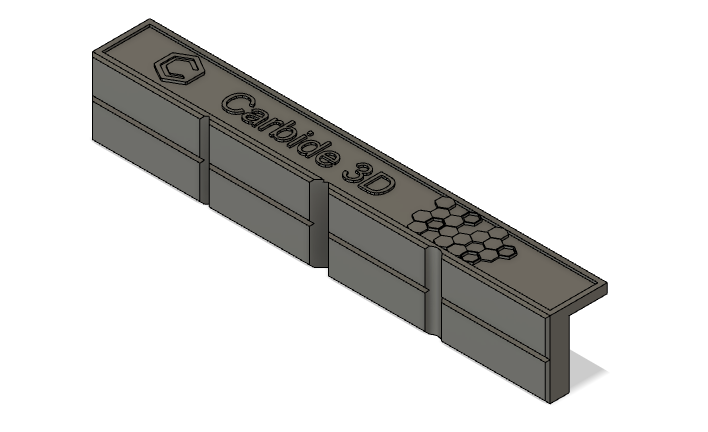
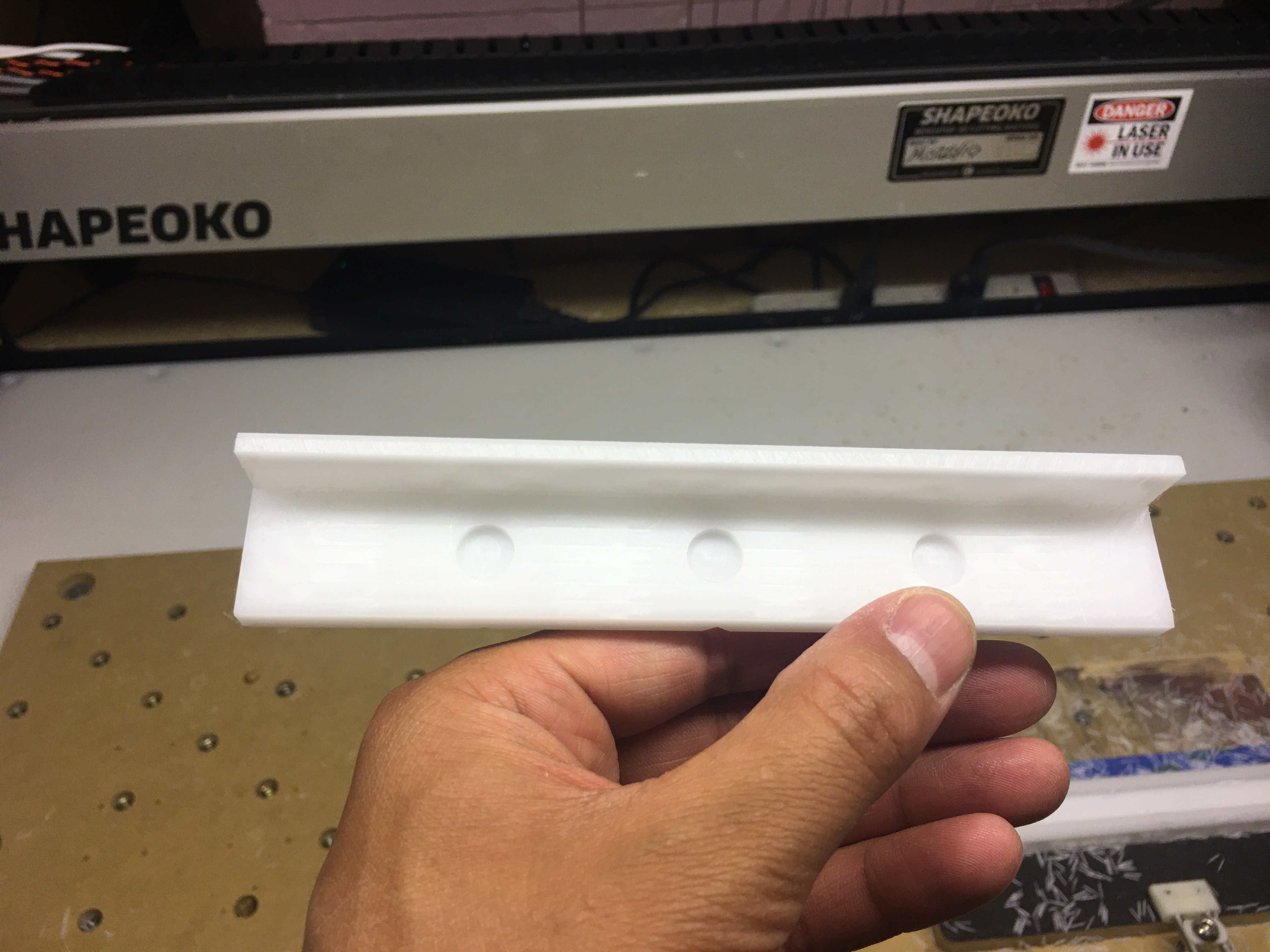
6in Vice Magnetic Soft(er) Jaws
Leftover Delrin and a bench vice that would be more useful if it didn’t mark up objects when clamping.
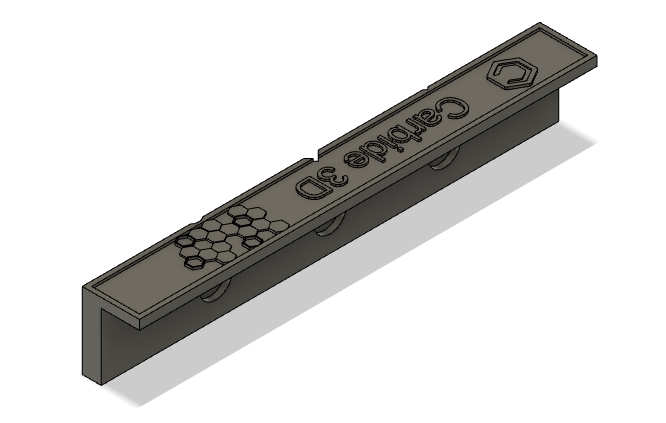
This one checked off a few boxes for me…
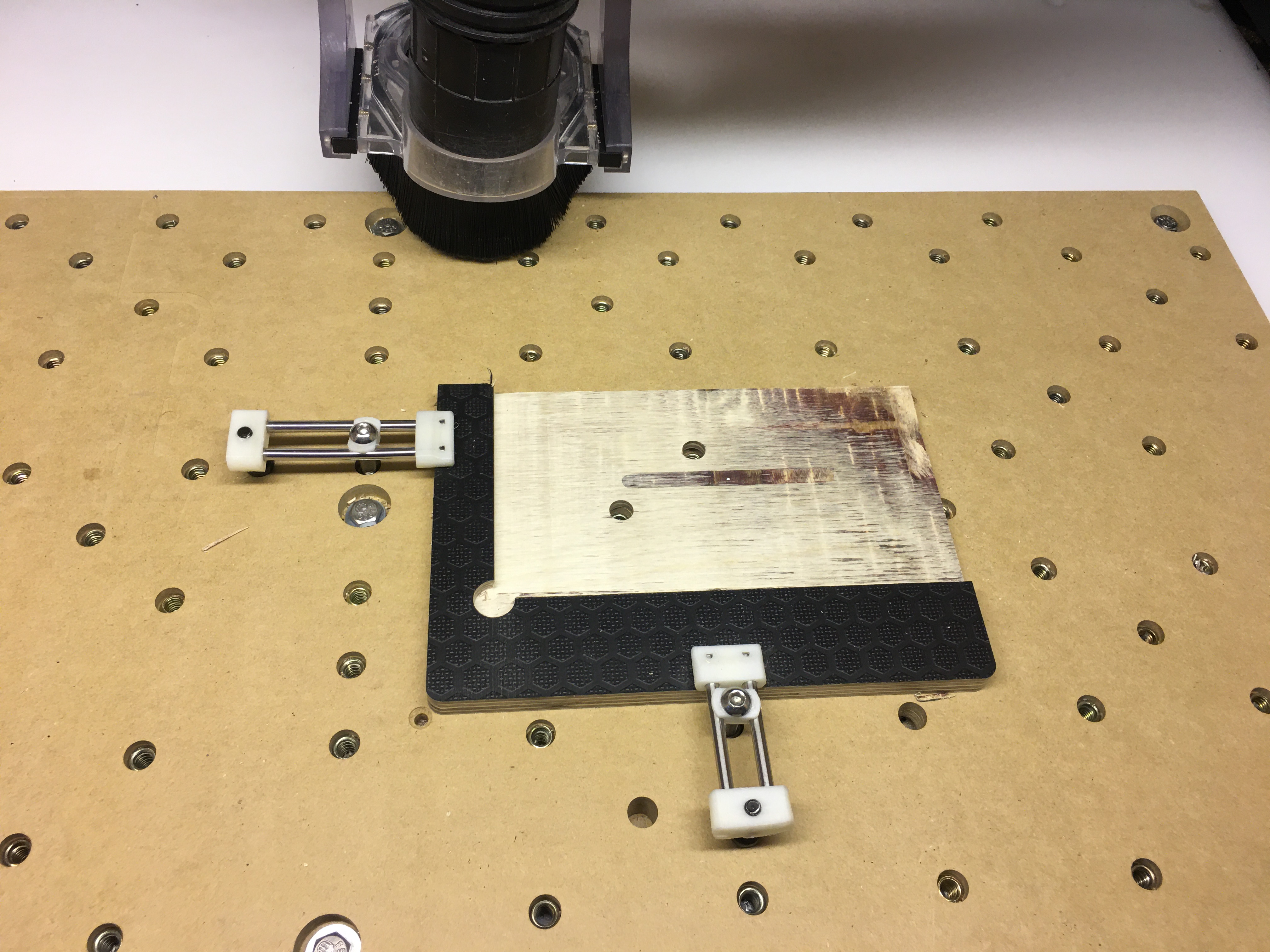
I built a corner square from scrap plywood (polymer coated on the outsides) so I could make a through cut without damage to my wasteboard, and also because I couldn’t spare any excessive cutting since my work pieces were close to actual size to start off, I needed to be aligned with the axes.
The first side machined was the working face.
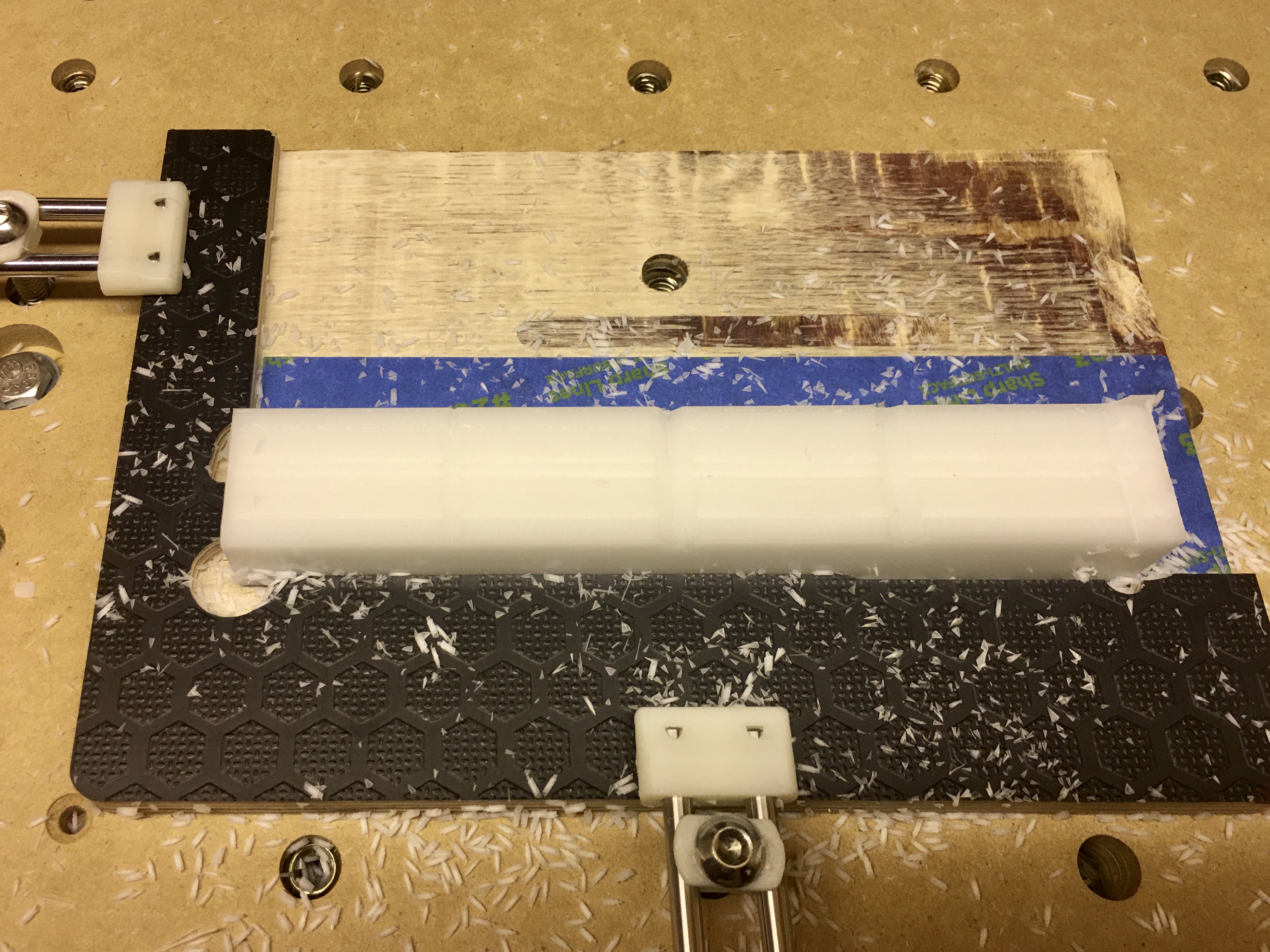
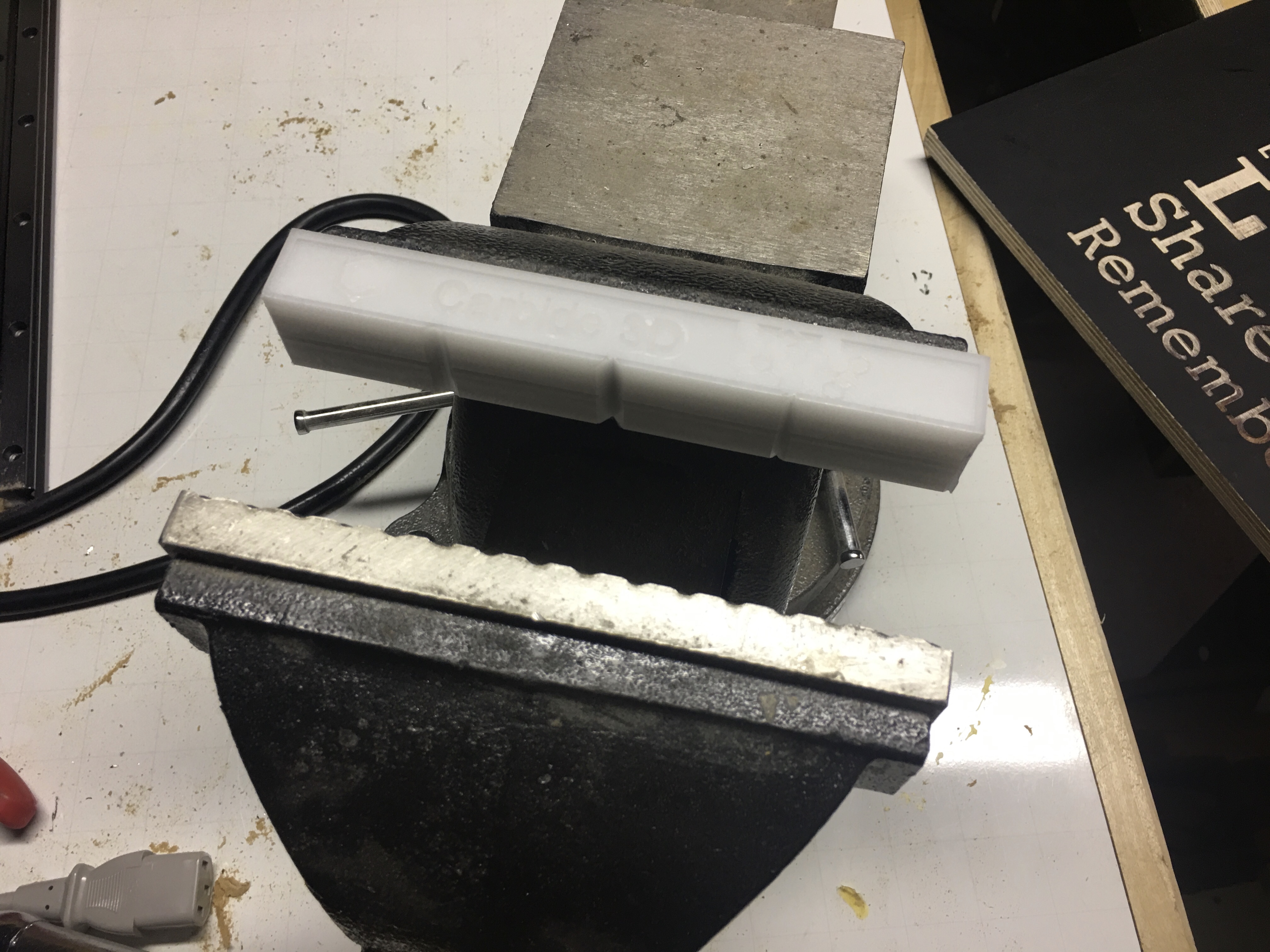
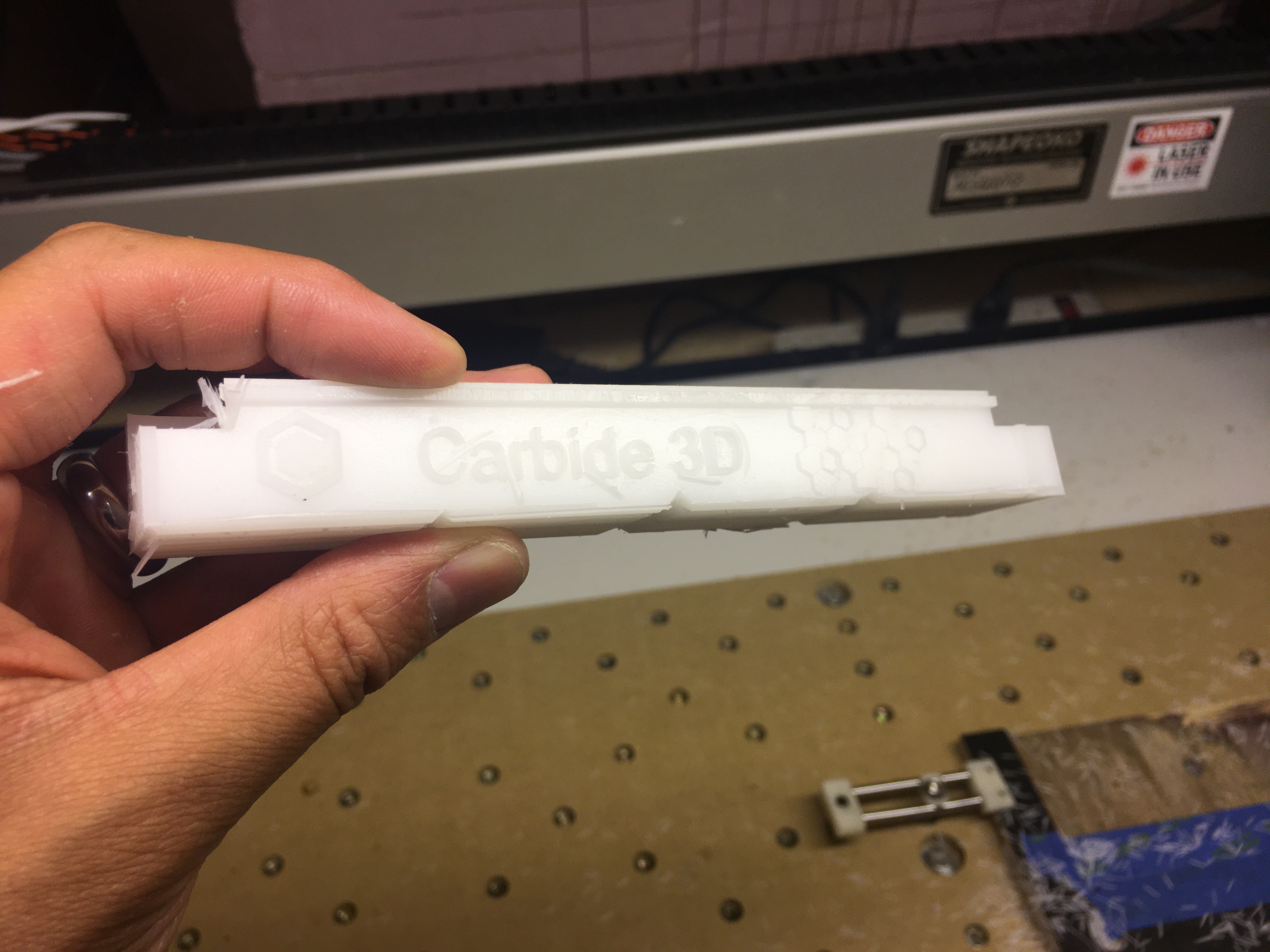
2nd side was the top side for aesthetics
Last set up was clearing the bulk and magnet holes
Unfortunately, I’m cutting it close. I hit many road bumps a long the way so I have to cut yet another pair, but to give an idea…
RIP
Time is up, voting is open!
Thanks everyone, fantastic entries (again!)
EDIT: oh, and happy 4th of July to all American Shapeokoers ! 


