Community challenge #11: multi-sided machining (closed)

The more you do on F360 the more you learn how deep it goes. These competitions definitely push me into areas of F360 I haven’t explored before. I used FEA on my plastic flexture in the last competition to check on the stress points. Not free but those few trial runs that are included to get you hooked!

This time around it is …censored… and … censored… !

2 Likes

So I edited my previous post to add pictures of the 2 ghosts I just finished last night.
Also whipped this up really quick:

I pulled this file into Fusion: https://www.thingiverse.com/thing:684102
Scaled it down by 50% to fit the nomad, and then cut out stock from carbide create to include holes at the corners for flip/allignment.

Used blue tape and super glue to hold everything down since that’s my preferred method at this point.


Didn’t really sand off the machine, because of laziness:


Fusion file: https://a360.co/3k3grK2

9 Likes

Got a question on the rules? Is it legit to post a project with the proprietary STL file portion removed (vcarve)? It seems that is keeping me from entering the contests and I’ve like to participate.

1 Like

It’d be something @Julien would need to weigh in on.
You could just grab something to do for funsies.

1 Like

Hi Gary,
The point of that rule is twofold

  1. that these challenges do not turn into “who bought the fanciest vector on Etsy and posted a picture of the awesome result”. That would sure get a lot of votes but most of the credit would go to the original Etsy artist, and that’s not the point.
  2. that folks get a chance to look at the toolpathing strategies used for entries.

Posting a file with the vector art removed would satisfy #2, but not #1. Also I would like to avoid some head-scratching when validating the entries for things that are “on the line”.

So to meet that rule the best would be if you can derive a non-proprietary version of your project. Replace the proprietary vectors with something similarly sized that you would create (or find, that is free to distribute), and rerun the cut ?

Alternatively, I think the C3D contests over on the Facebook group are based on “pictures-only-no-questions-asked” entries (I know this was not your question, and you may or may not want to visit the FB group, I am just mentioning this in case anyone is interested)

6 Likes

i dont know if the challenge is over but here is my entry, im still learning but im having fun. its not a difficult piece buy it the first time ive done anything thatrequired me to cut another side more less 6 sides but here it is…

i started out with a small piece of scrap that measure 1.5"x 1.5"x 1.5" . i had to build a fence on my XXL so that i could repeat the same cut 6 times. had a hard time trying to figure out hold down methods, usually working with thinner flat stock hold down is easy but this being so small was different. i think next time i’m gonna adjust the circle sizes see how much stock i can remove

7 Likes

Hi @millerasm,

The contest is still open (until Aug 2nd), thank you for your entry. Don’t hesitate to edit your post to tell us about the process you followed, difficulties you may have encountered or tips you would share, things you would have done differently, etc… ? That’s a large part of what makes those challenges interesting for others.

3 Likes

HI everyone!, here is my entry:
Created a ride on plane for my 18 Month old son. it has two sided work for rounding both edges on all the surfaces as well as some pockets in both sides of the wings for fasteners and positioning the wing posts and wheels.
for alignment I used a fixed edge on the top and right(end of the wasteboard), and a small pin hole in the middle of the board the size of the bit. i got this idea from cnc nutz in youtube.
it was designed in Fusion360.

Here is the alignment pin and fixed edge:


Some project images:


Main Difficulties:
Ok first of all the most problems I had with this probably should not happen to most as it was with the round over path

  1. I have no experience in woodworking or own a trim router other than the one in my SO3.
  2. I have the SO3 (and very little experience) so decided to let it do the work.(anyone else with some woodworking knowledge could avoid this by using a trim router and would have less 2 sided pieces.)

The problem was: I created the model with all the fillets in place and created references from the rounded edges. when i went to create the cam and chose my round over bit i could not get it to work right. i needed the original edge for the path, so went ahead and deleted all the fillets which caused havoc in my Fusion file and lots of lost references.

So as far as i know my suggestion would be to do all the modeling without the fillets and at the end add all the fillets you want for renders and reference, but this way you could suppress them for CAM and not have them mess up your model.

Note: As of august 4th 2020 fusion 360 added a Manufacture working model, you have to enable it on preview features but this solves my problems with the fillets as yo can edit this model for manufacturing without altering the original version and is probably a better option than my previous suggestion.

and then i had some fit/size issues which i had to create additional pieces like a longer seat post and some other revisions.

Fusion file link: https://a360.co/30VNzL9

13 Likes

@Ahaddad very cool, and nicely done, your son must love it.

All, with the deadline on the horizon, now is a good time to double-check your entries vs the rules in the first post.

Listen! I can almost hear @Vince.Fab’s entry around the corner (and it sounds like a muscle car)

3 Likes

Thanks @Julien, you can’t imagine what a tough critic he is :slight_smile: I’ve had to scratch a few projects when I ask him if he likes them on the computer screen! Also I will edit my post tomorrow to add some information on the complications as I did have some.

4 Likes

Modeled in Fusion from drawings, programmed in Fusion, individual parts are then assembled. I don’t have pics of finished product.


U2 Standard v1.stl (2.4 MB)

16 Likes

I am unable to edit my posts to include the Fusion Models so here are links to them.
Sail Boat https://a360.co/3fblt3K
Dish Holder https://a360.co/2DopzrK

1 Like

Thanks ! I edited your posts to copy/paste those links there too so that it’s more convenient for people who would want to open them.

Latest thing, and possibly the last before the deadline:

So I’m no Syman woodcarving, who does amazing work, but I do have a robot, and really like the idea of making some pokemon on the CNC.

So I landed on making Pikachu, because it seemed easy? I should’ve done like diglett or a ditto or something. (You should google those pokemon if you aren’t familiar)
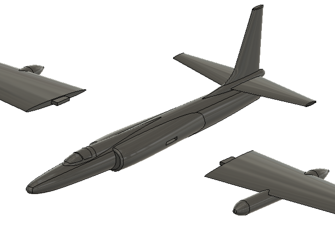
Anyways! I’m not about to model things myself, because I’m lazy in some aspects (most), so I went on thingiverse and pulled this model: https://www.thingiverse.com/thing:3877926
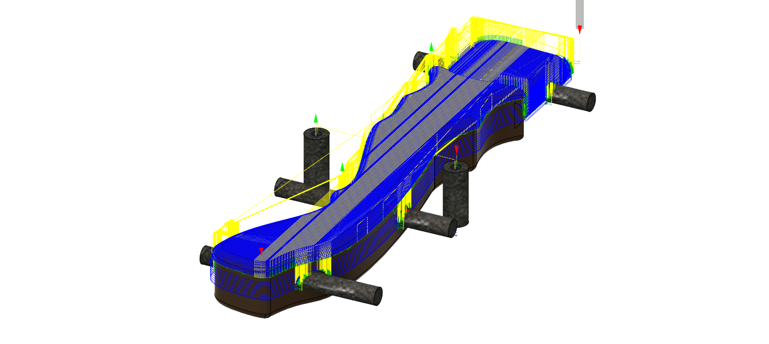
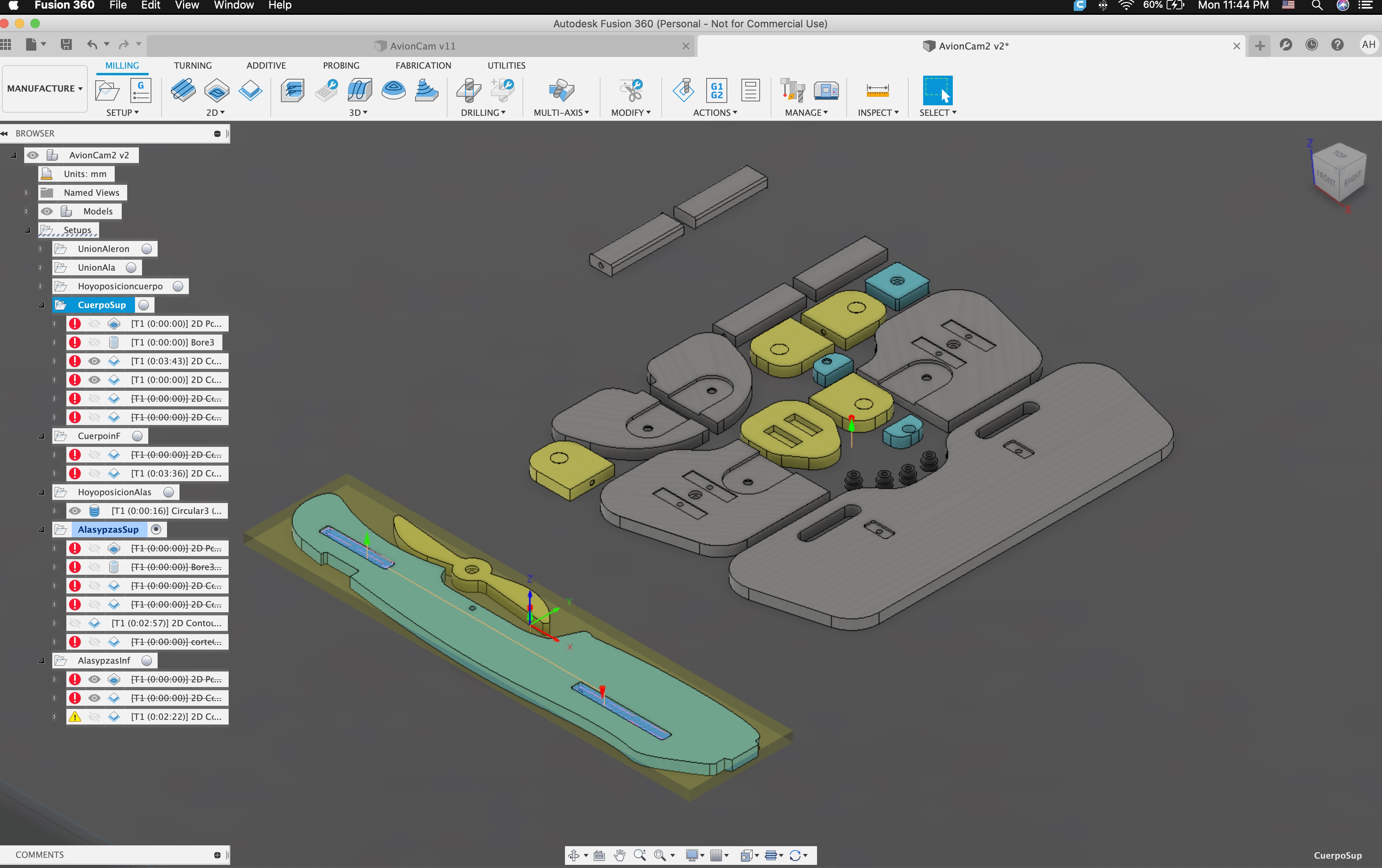
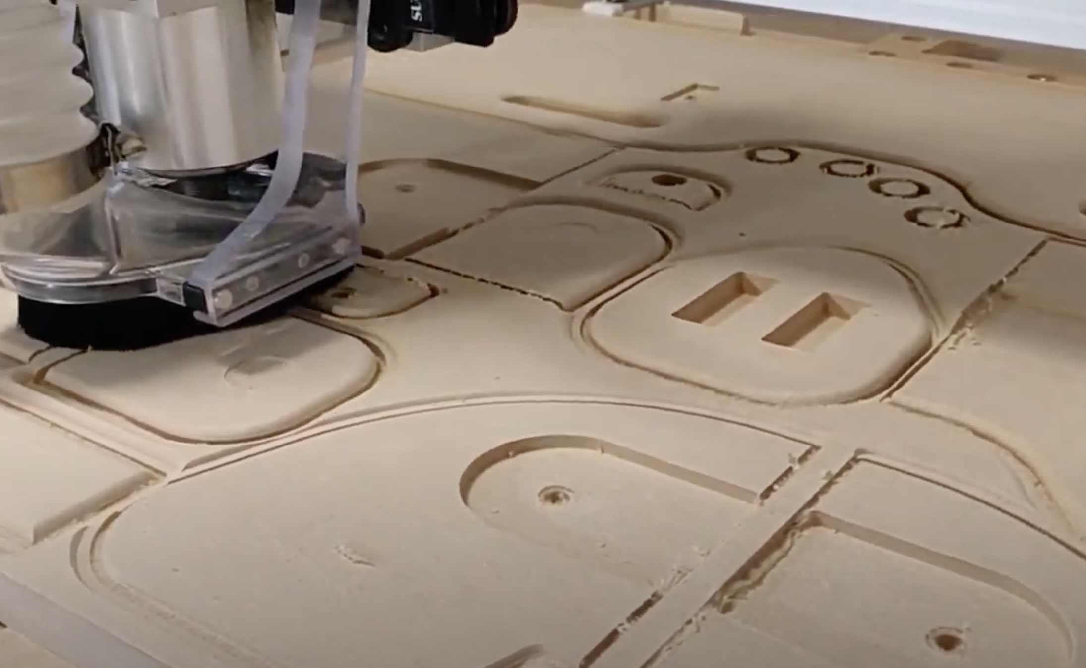
Uploaded into Fusion and then realized I’d have to run this in at least 4 operations. So after watching @wmoy super useful video here: https://www.youtube.com/watch?v=IQ3dzFRZlKM I got to work doing the work in fusion. I had a few challenges, but for the most part things ran alright. I did change some things live (like running the front and back at ~60% for some of the roughing), but for the most part thins turned out alright.
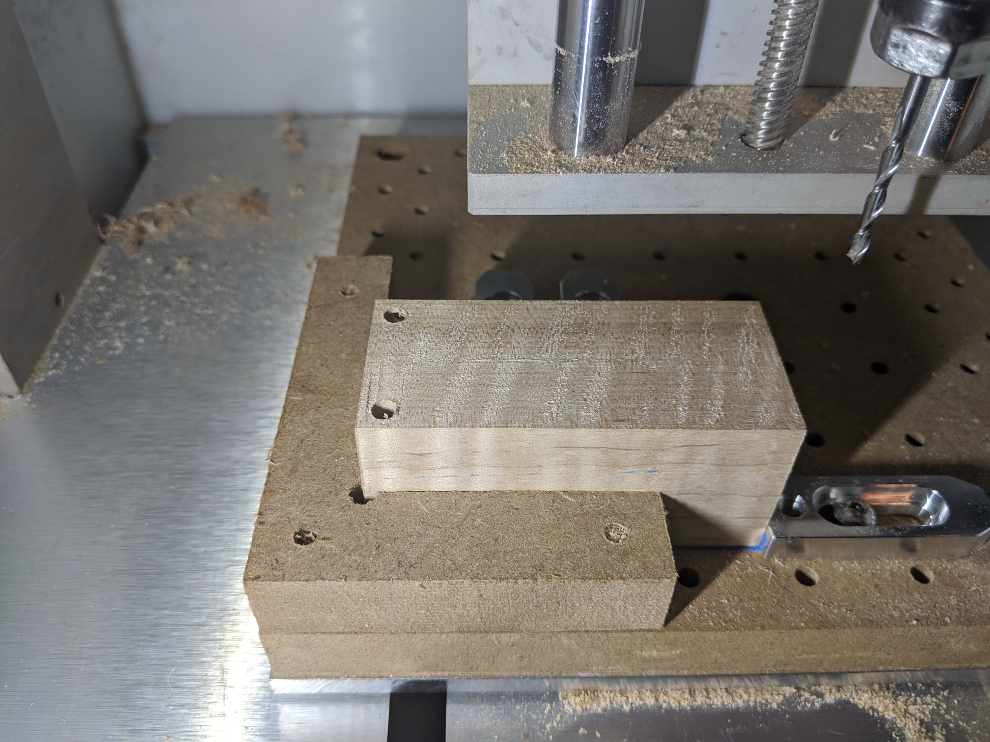
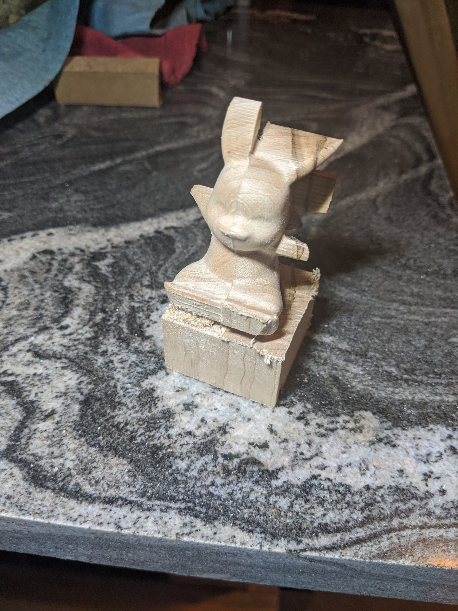
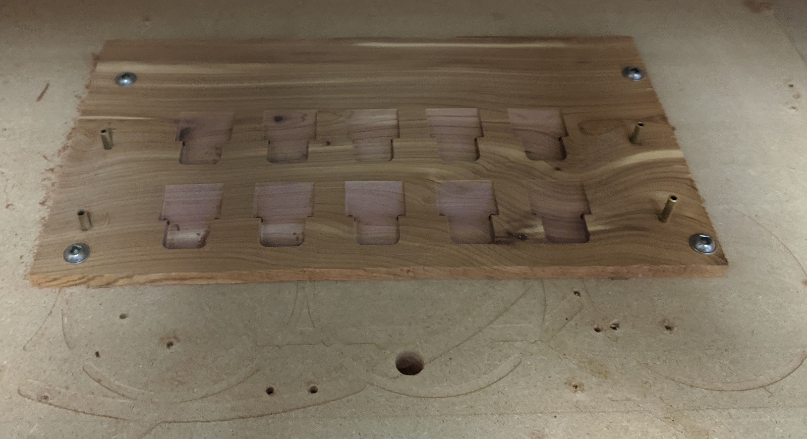
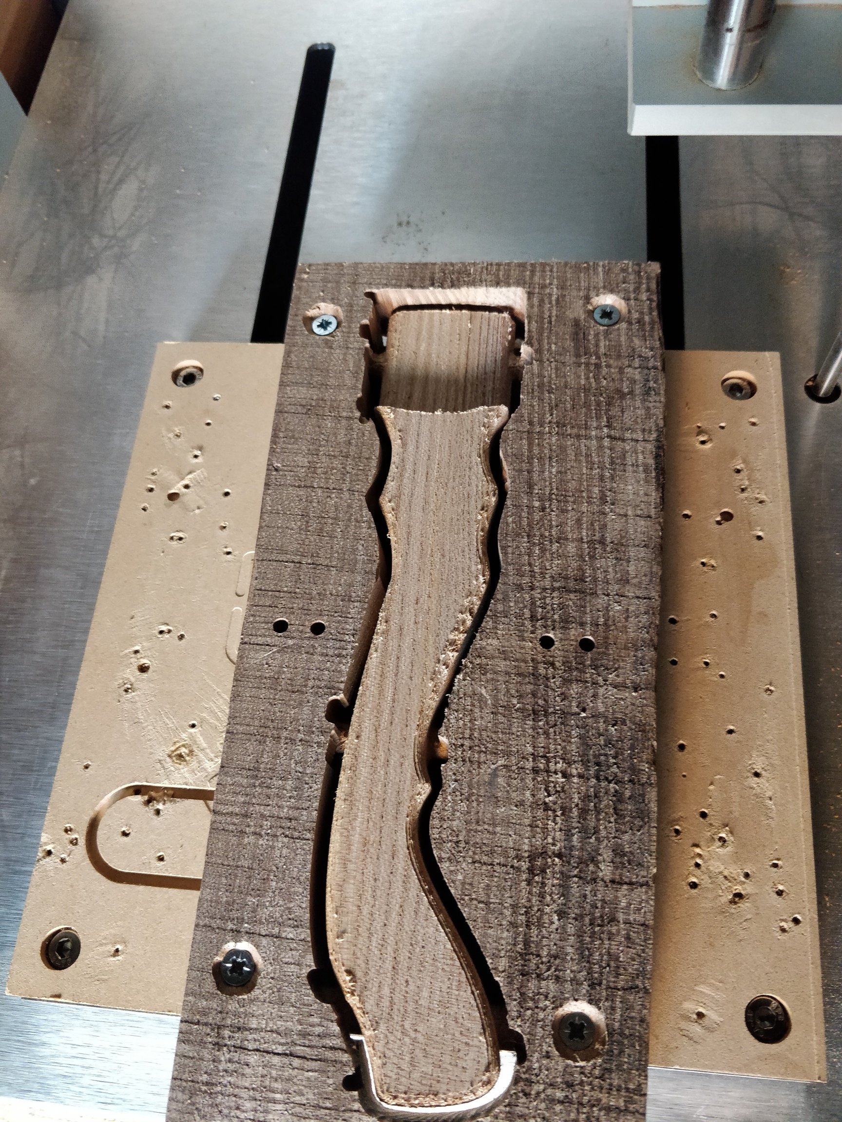
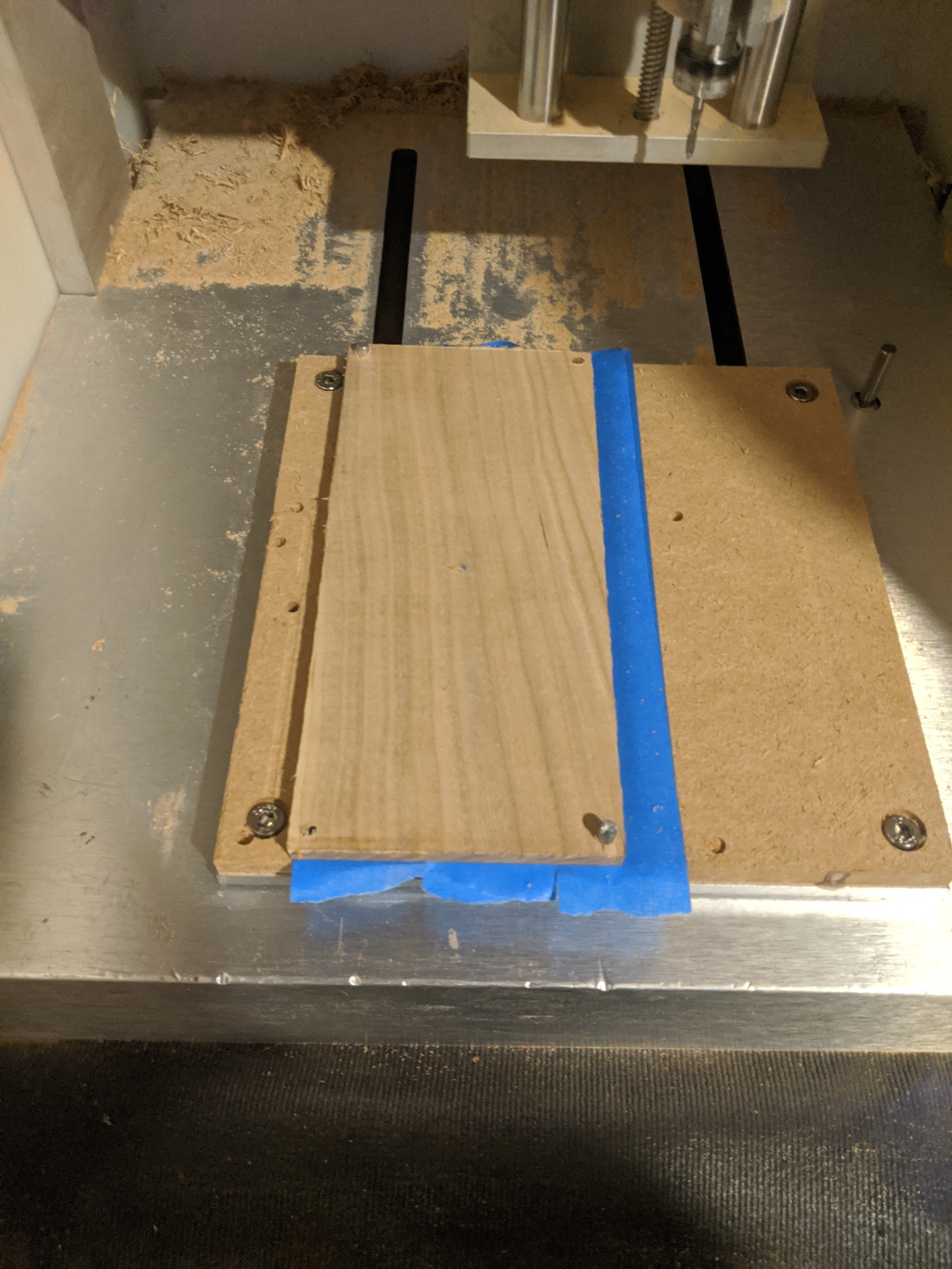
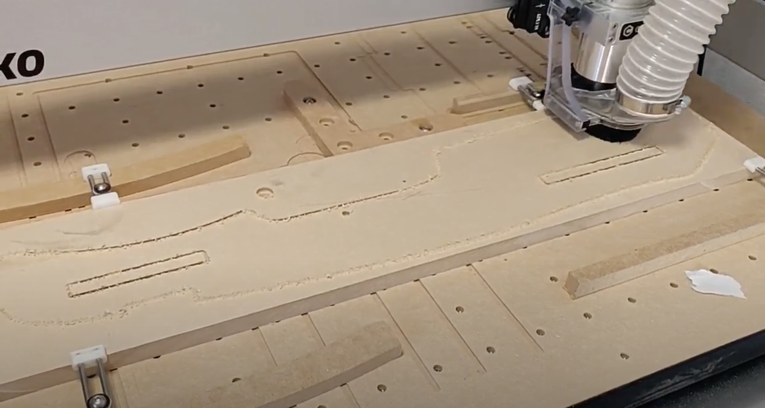
I used a square in the corner of my machine to hold the stock against:

I was going to use holes for flipping, but that got scrapped.
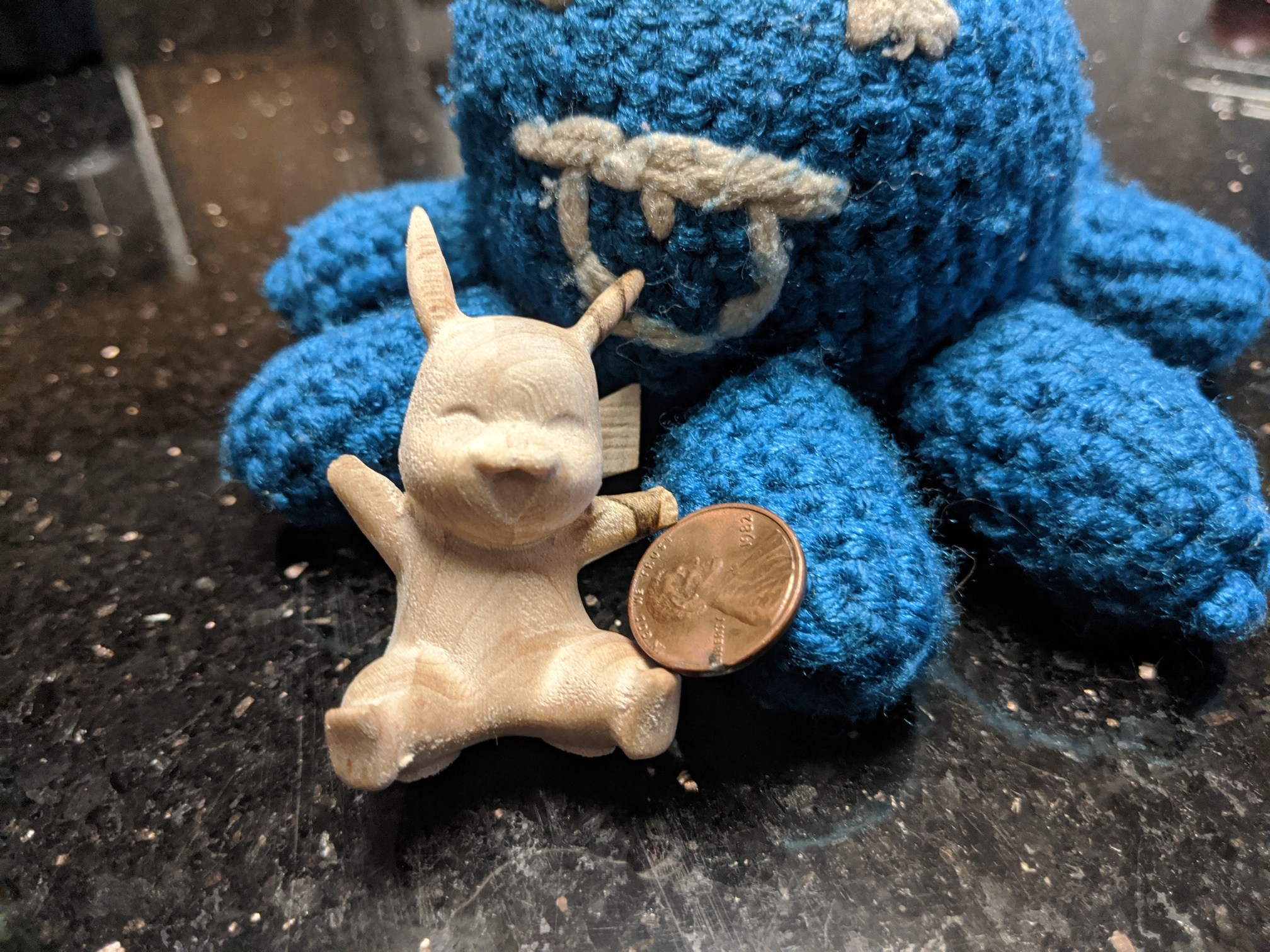
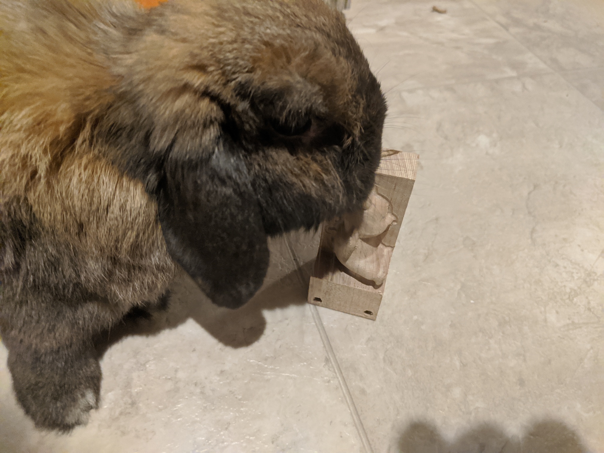
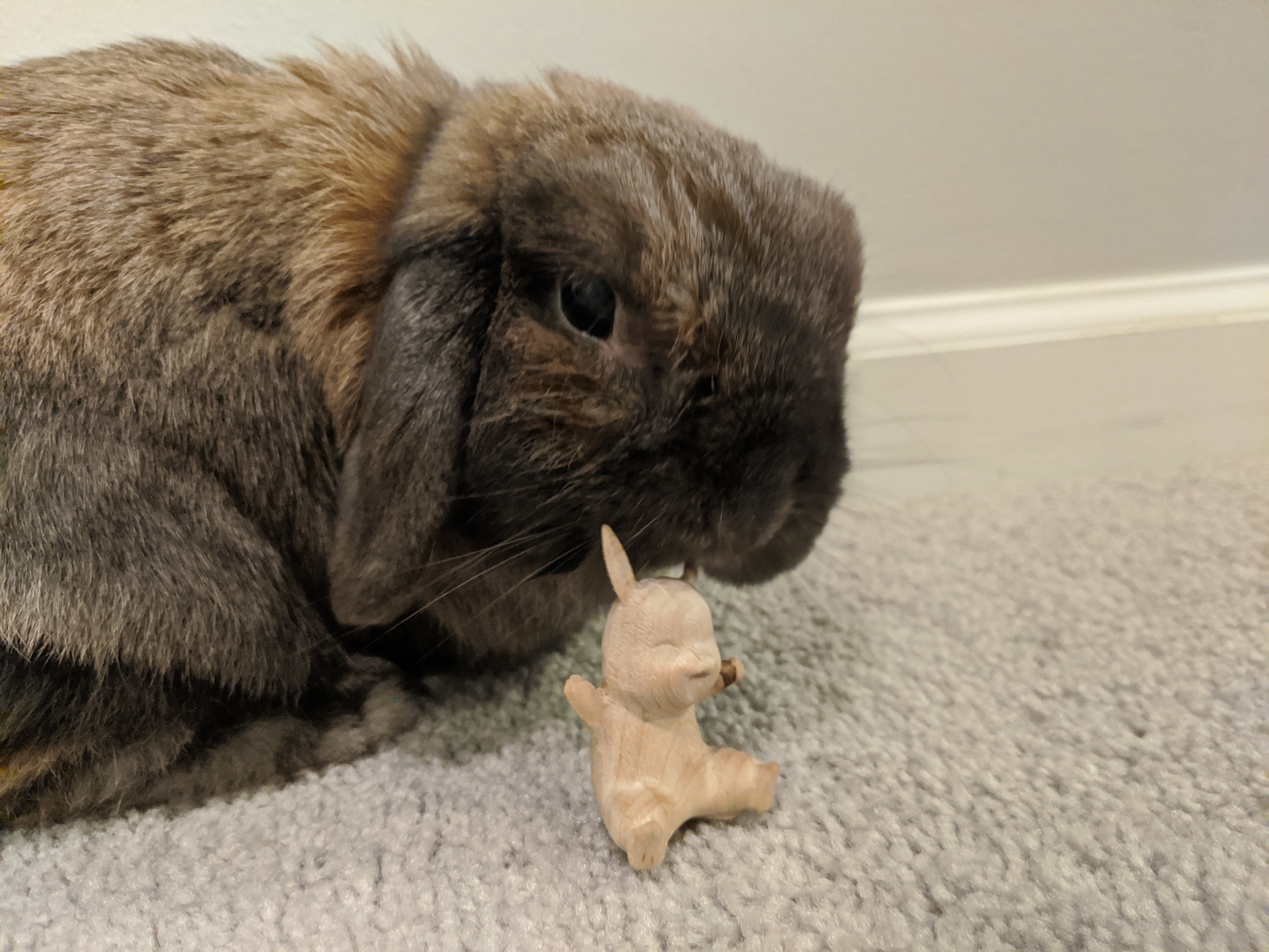
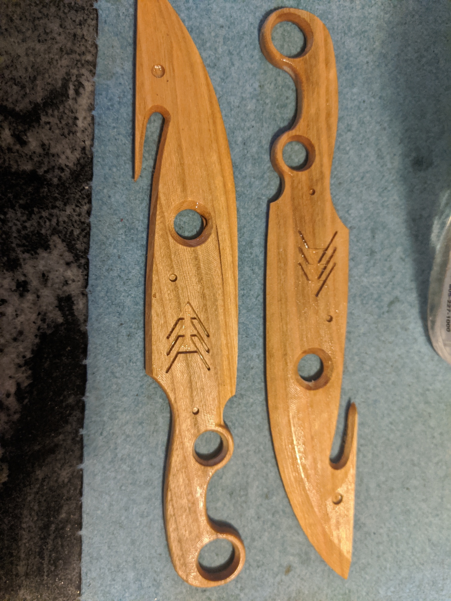
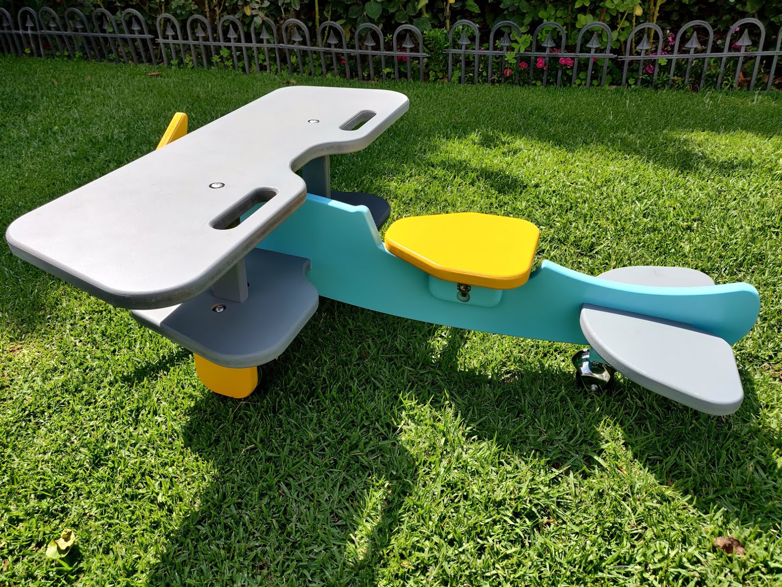
Side 1 finished fine and was bunny QA checked:

Side 2 was alright looking as well:

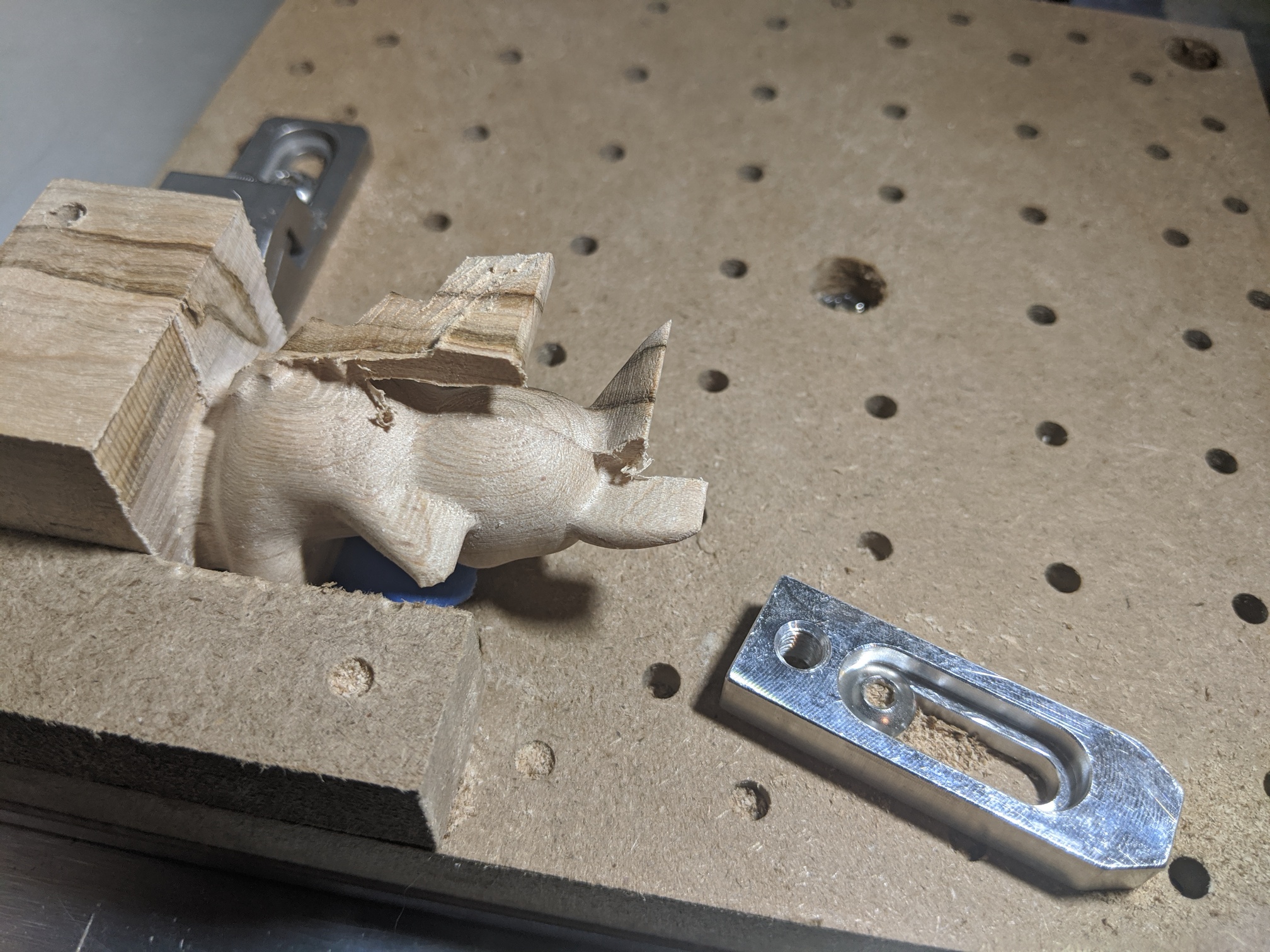
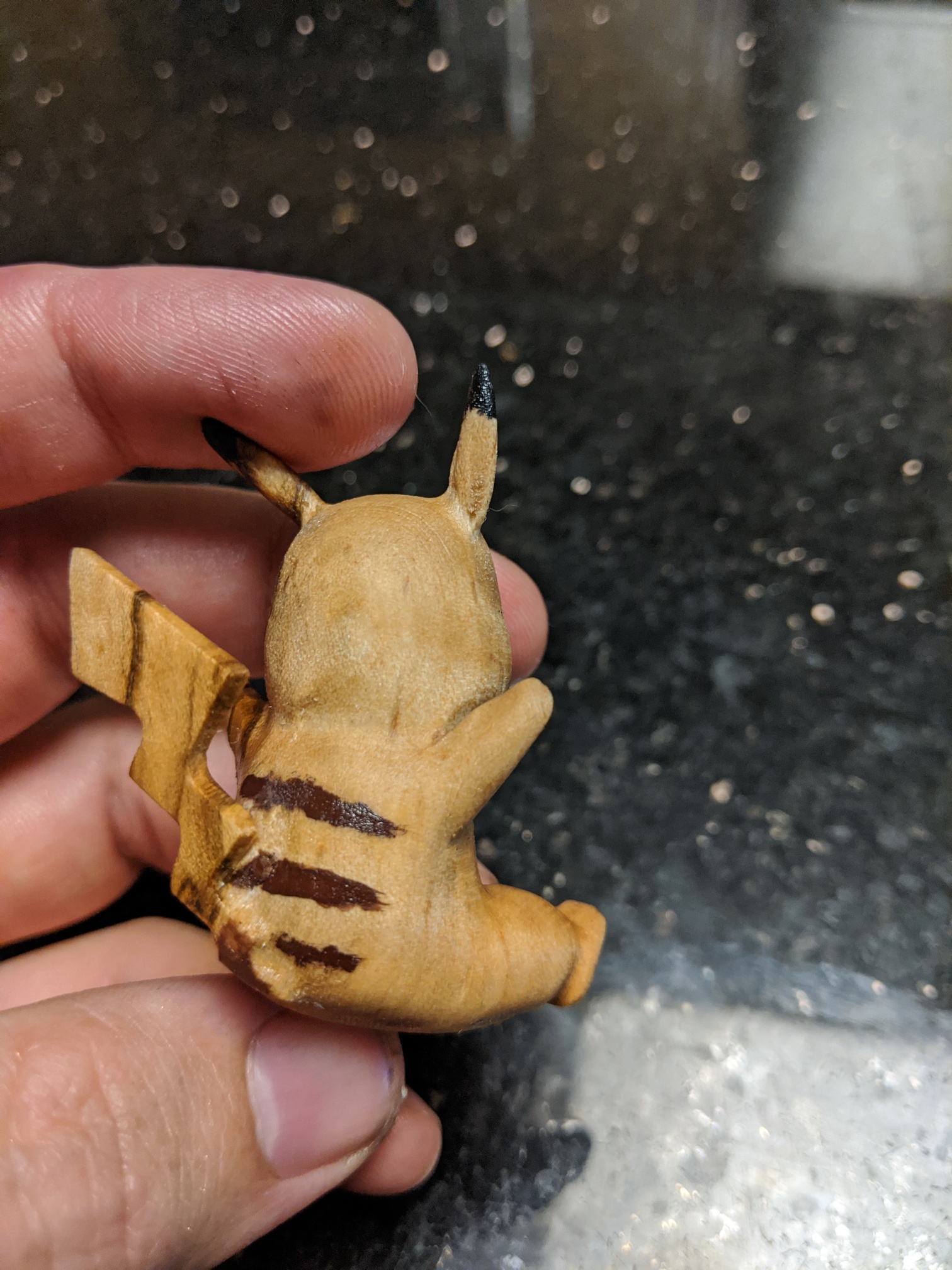
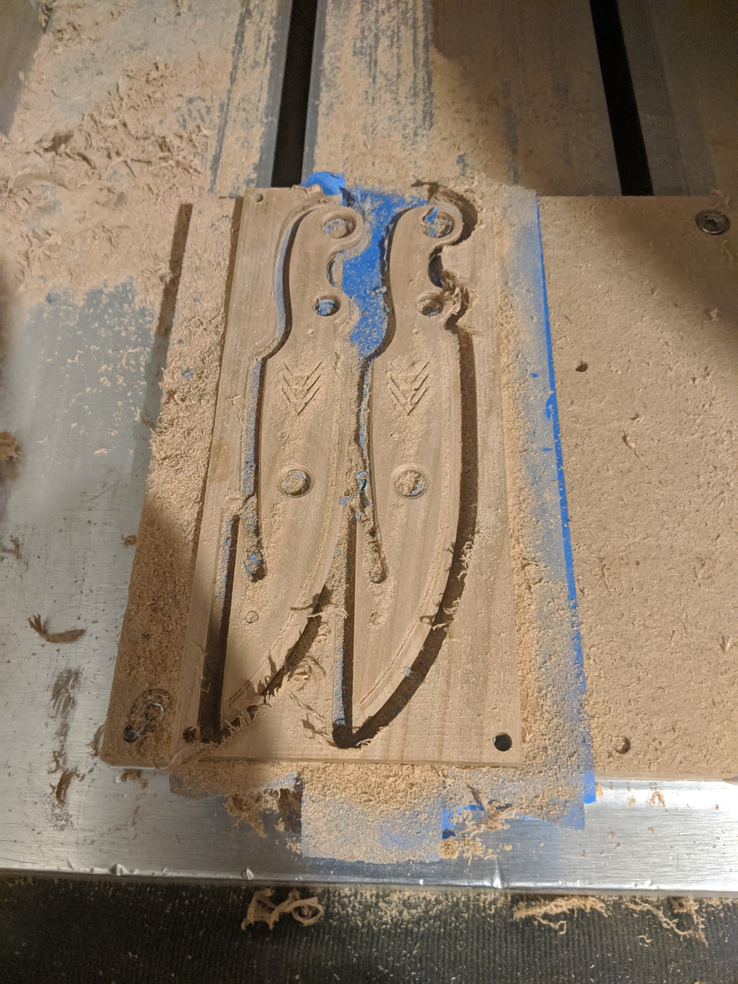
I think machining the back is when I switched over to the tiger clamp (which is amazing, I highly recommend picking up a set):

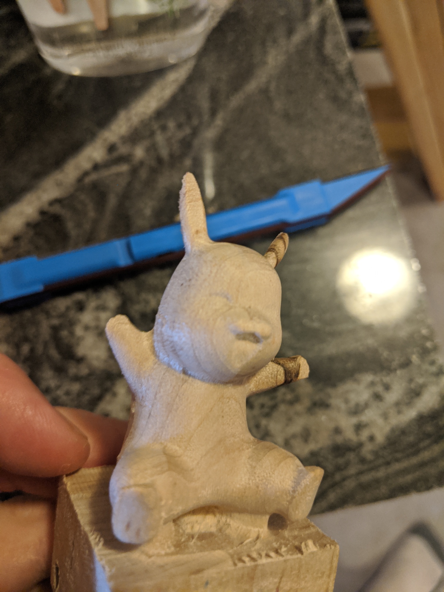
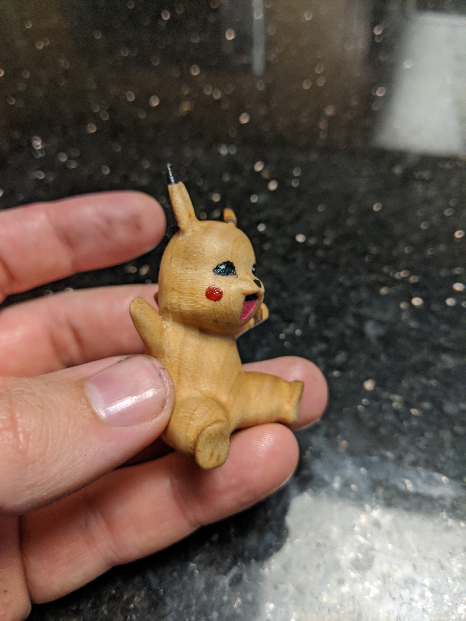
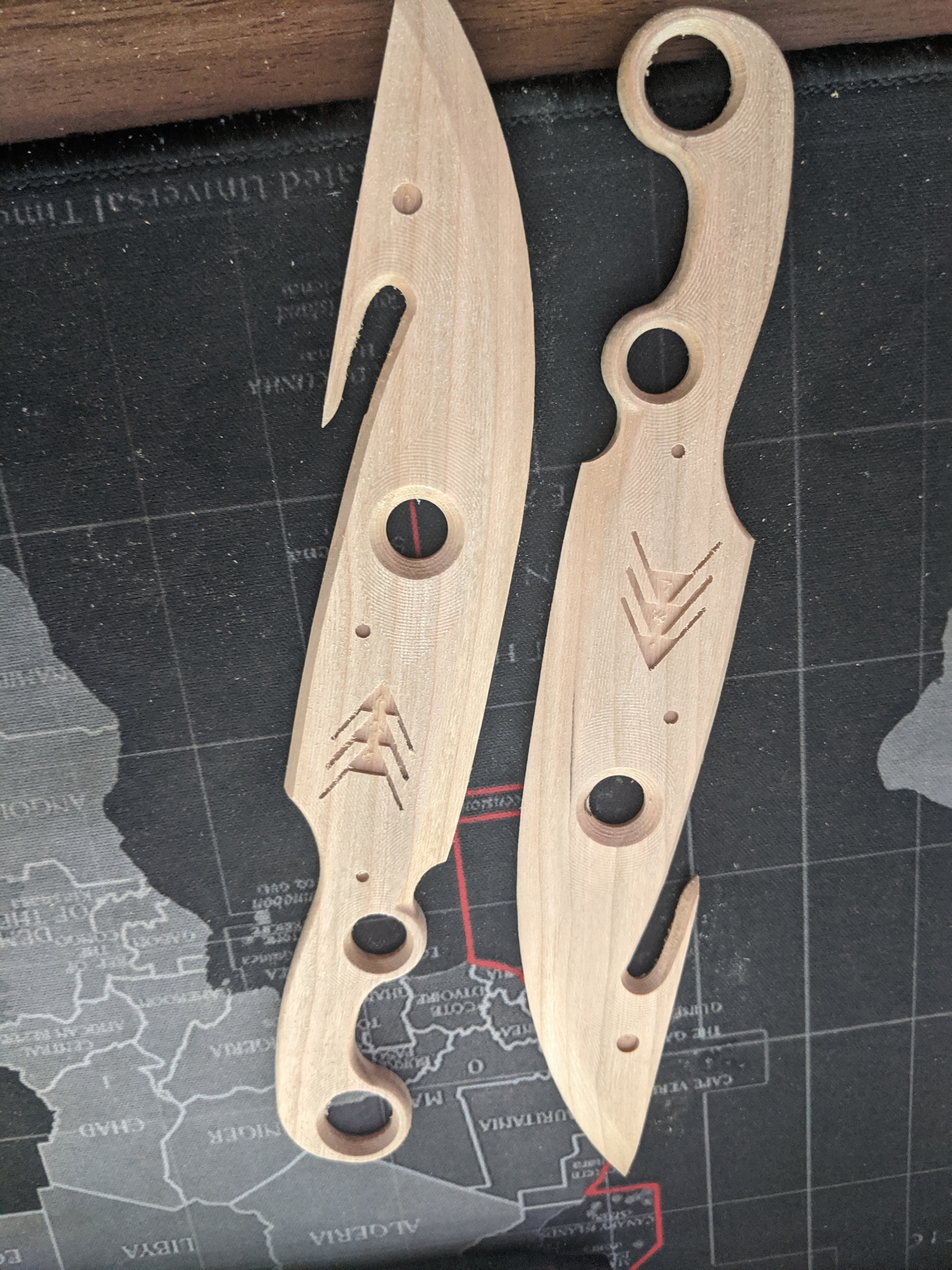
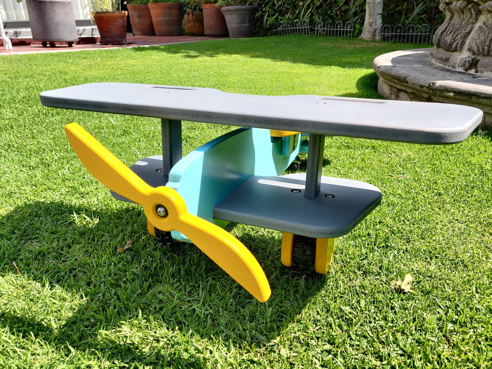
Front face looked alright:

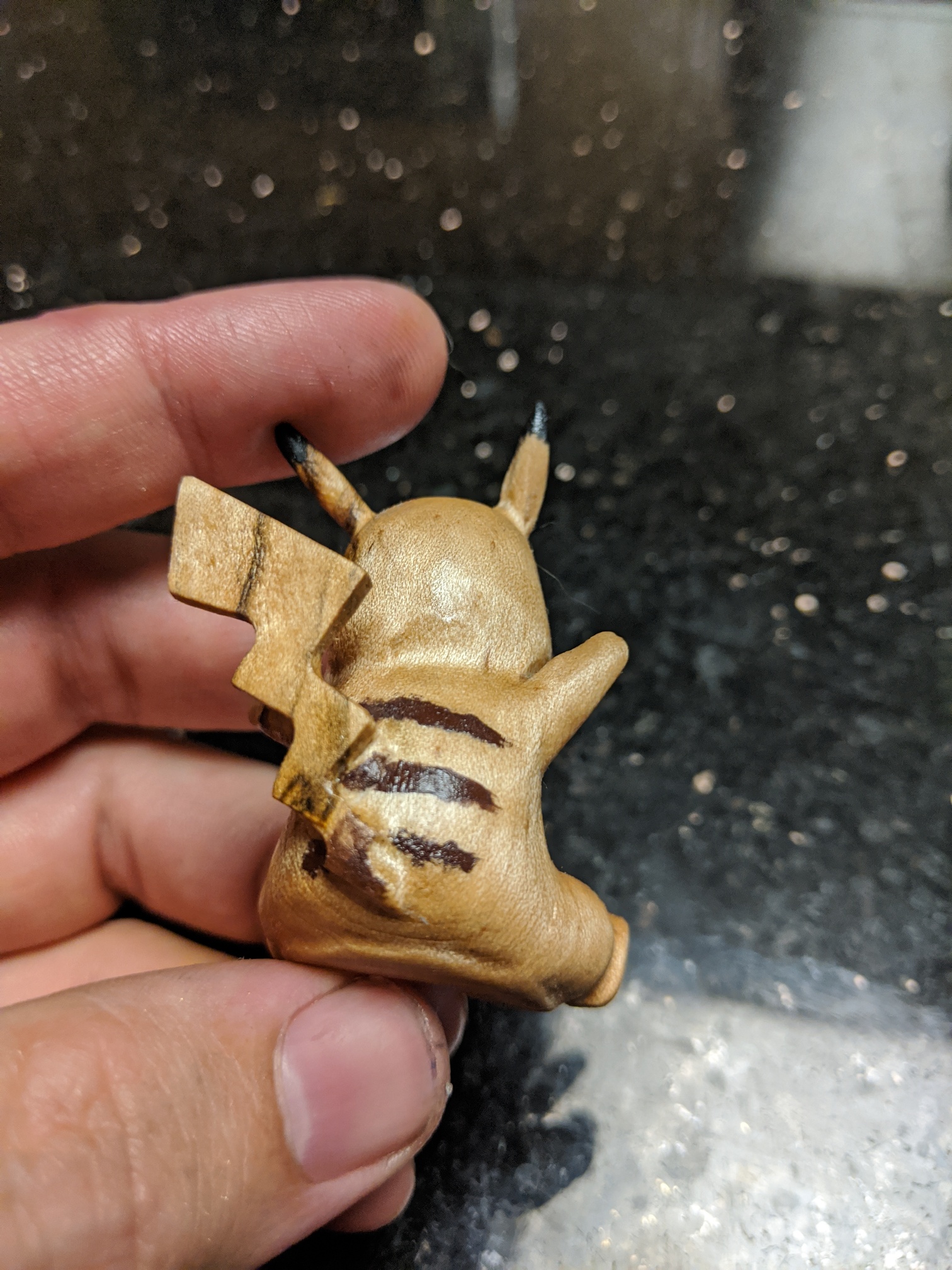
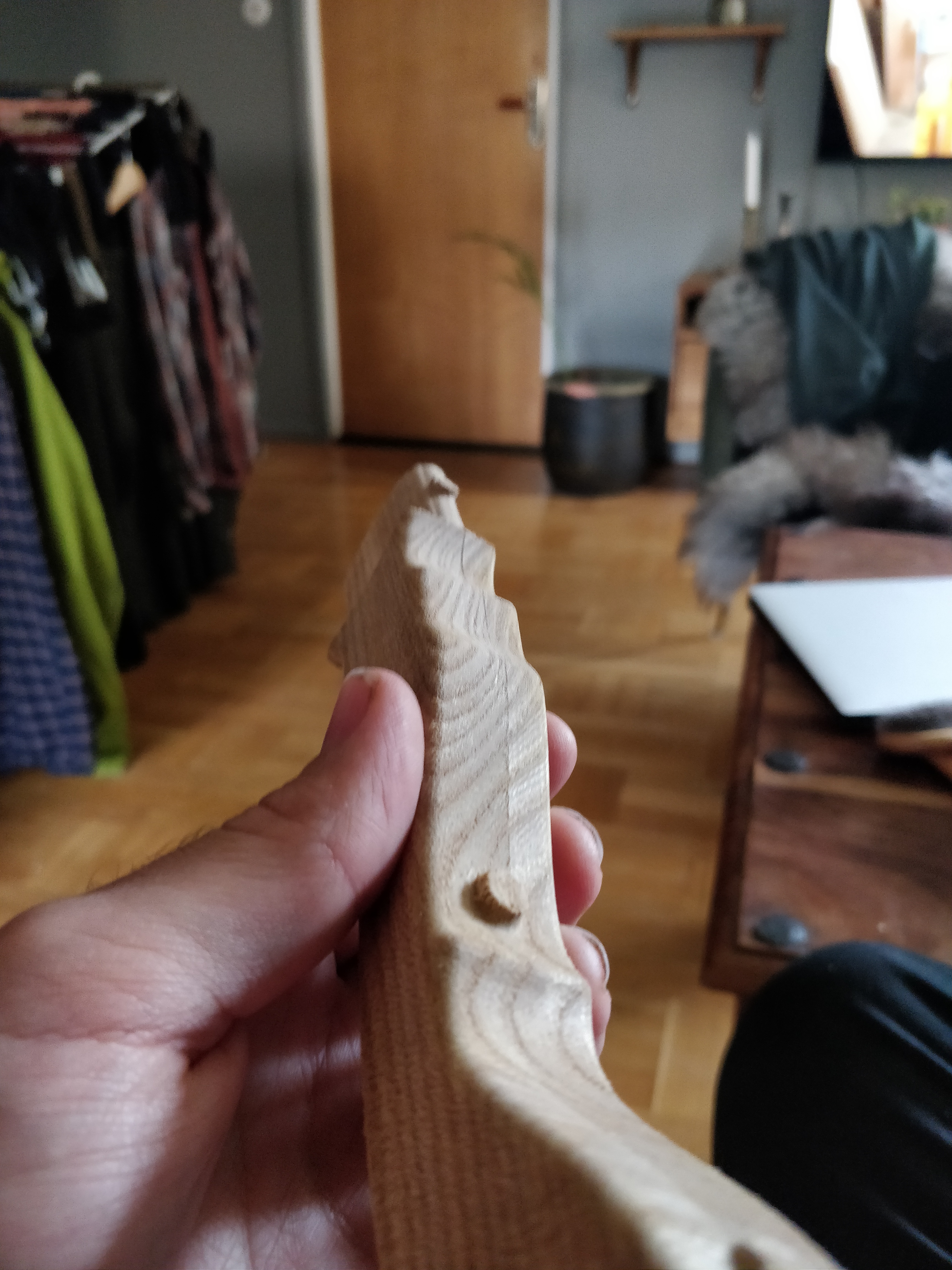
I have to do some slight sanding (and a bit of carving) to hit where the machine missed. Obviously this would be way easier on a 5th axis. Some geometries are harder to reach with the smaller 1/16th inch endmill because the cutting distance on the endmill doesn’t reach where I need to have it reach. My main long reach endmills are 1/8th inch, and weren’t able to get in the area where the arm is close to the head.
I also didn’t save the result from previous operation to save myself machine time on the back and front (I machined left and right sides first), which would’ve taken this from ~8 hours of machine time down to maybe 6 hours? Maybe less. Saunders has a video about this, but basically you export model in preview mode as a .stl and upload that as the stock file.
Still pretty happy with this overall, and not a bad test of 4 sided machining. I’m also not sure how woodcarvers have the patience for this stuff. I tried filing the gap between the arm and head a bit, and I’m already tired of this.
Sorry for the giant wall of text. Here’s another picture:

https://a360.co/2XjnrbZ

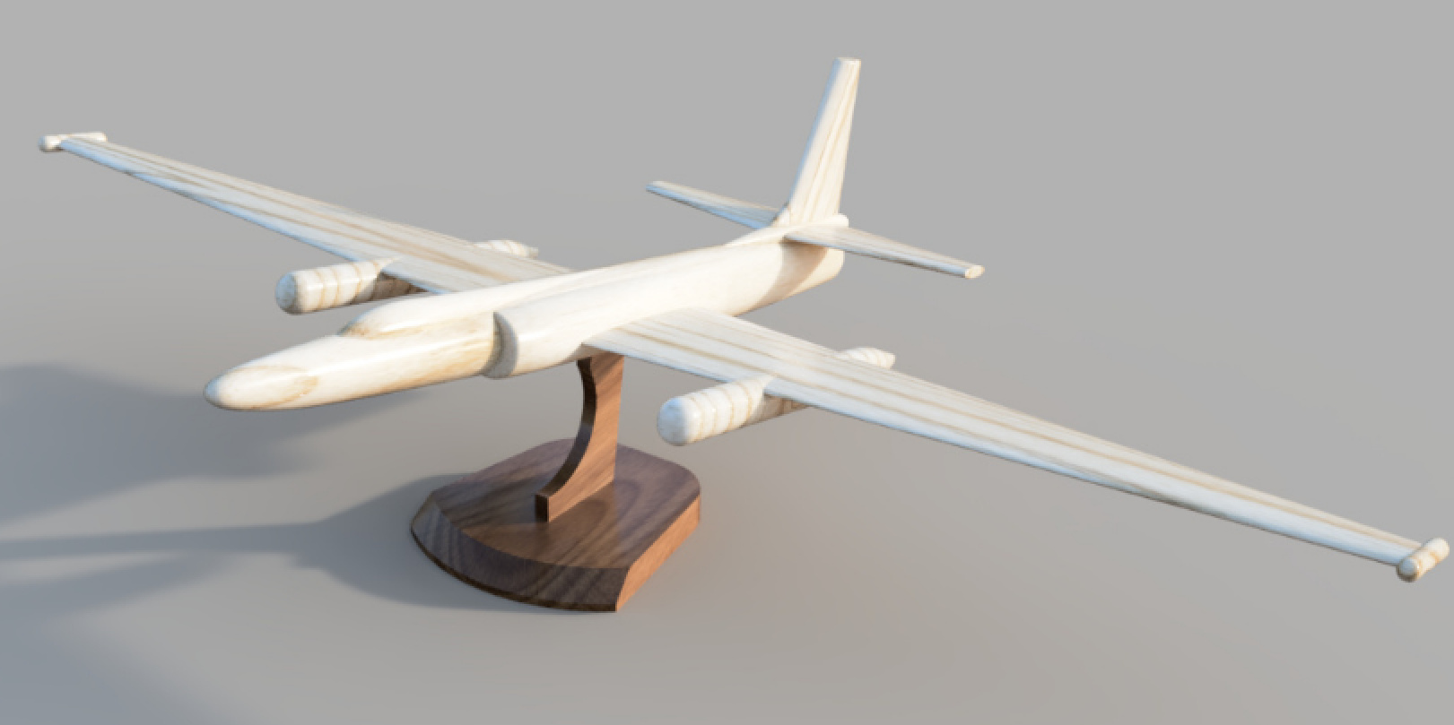
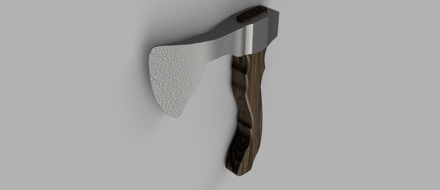
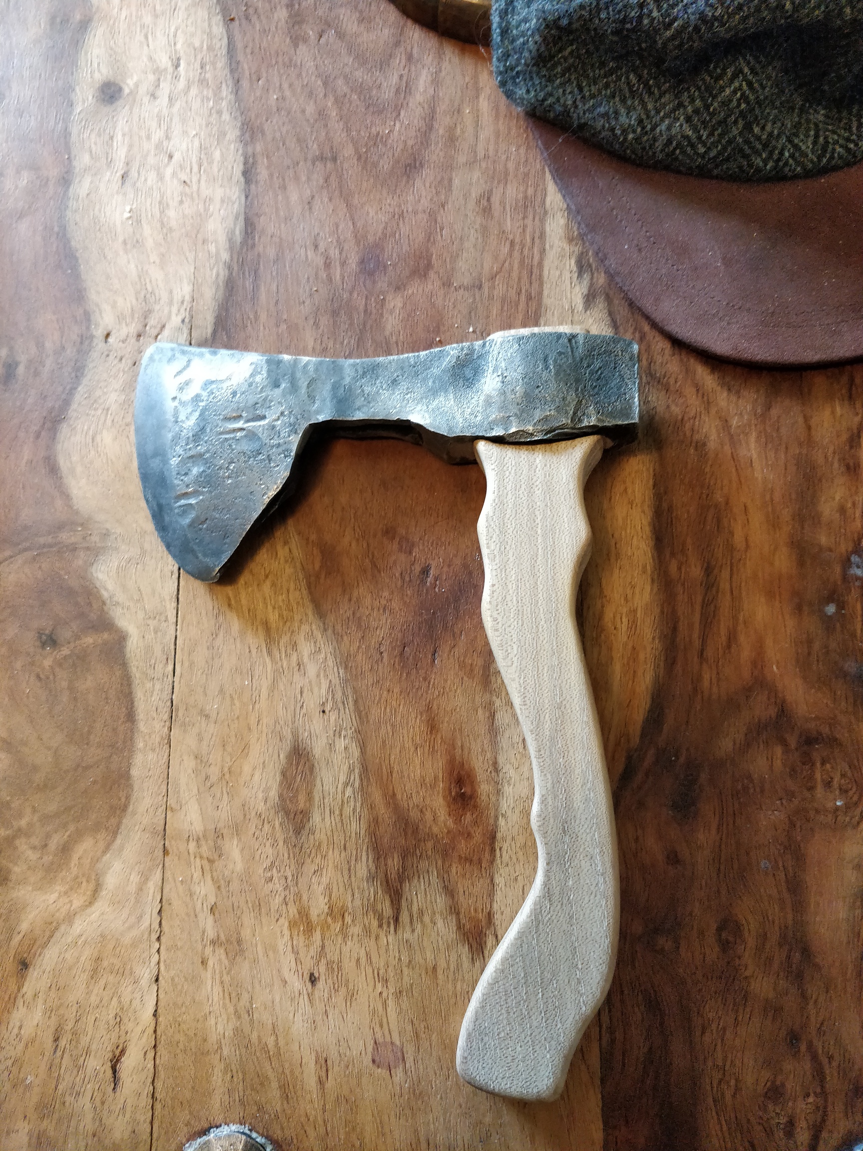
Edit: did a bunch of sanding, and then painted it and put some finish. I dont know how people have patience for this kind of work.


Certain parts are a bit shiny, which is neat. I really like curly maple sometimes.

16 Likes

I used this contest to finally figure out Fusion 360 CAM tab. I built a stand to hold all of my switch cartridges when they are not in use. I modeled thia a long time ago, but could never figure out Fusion 360’s CAM / manufacturing tab. I used a 0.0625 ball nose and 0.125 end mill and cut it out of 0.25 red cedar. Still need to add a coat of finish.

To carve on both sides I used slightly oversized stock and drilled 1/8 holes that I had dowels inserted in. I started with the wood just taped to the spoil board and then used the CNC to drill 4 holes for screws. I use the coarse kreg pocket hole jig screws which hold great in the MDF. Once it was screwed down I then used the CNC to drill 4 holes that extended 1/4 inch into the MDF and inserted dowels. The holes were spaced so that they were 9.525 mm on either side of the stock. When the front was done carving I then flipped the board over and used the dowels to locate. It worked great.

One mistake I made was using a down cut 1/8 end mill bit while drilling into MDF spoil board and ended up producing a little smoke in the MDF, nothing serious, but definitely something I don’t want to do again.


https://a360.co/39M49RL

11 Likes

12 hours to go - and a dash to the finish for @Vince.Fab and myself…

1 Like

more like 22.5h hours (as I’m posting) ? Deadline is “tonight” (Aug 2nd, midnight PST)

I thought I would share another part machined this weekend. This project that has been on hold for a couple of years, but having recently acquired the Nomad I had no excuse not to finish it.


I did a black smith course a few years ago and has put off making a handle for it until this weekend. I drew up the axe I made in fusion 360 by importing a picture of it as a canvas with a ruler below it for calibrating the image.

As I severely lack any artistic prowess I googled for an axe handle that I liked and imported it as another canvas into fusion and scaled it to a size I liked and drew up the outline of it.

I drew three pins through the handle to keep it in place for the machining and added them to the model surfaces for the 3D toolpaths. I cleared out the majority of the material with a 1/8 inch end mill and finished with a 2.5 mm ball end mill. I flipped the part and relocated it using 4 mm dowel pins. Its machined from some mystery wood I had laying around, I think it is oak.


I secured the axe handle with a piece of walnut and a cone wedge.

Here is a link to the fusion file: https://a360.co/30jFnFh

Here is a link to the project uploaded to CutRocket: https://cutrocket.com/p/5f271423ec3e9/

12 Likes

@Radiation: nice Pikachu and cute QA bunny !
@dmouw25: I like what you did there using both sides to mill tapered slots, I’ll make a note of that trick.
@Olle: it must feel good to own a 100% DIY axe ! I like the very “raw” look of the head. It seems like you went to the limits of the Nomad bed size too for this project.

3 Likes

Don’t forget to post to Cutrocket.

4 Likes