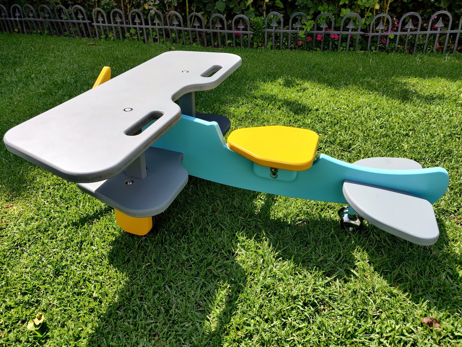
Community challenge #11: multi-sided machining (closed)

Hi @millerasm,

The contest is still open (until Aug 2nd), thank you for your entry. Don’t hesitate to edit your post to tell us about the process you followed, difficulties you may have encountered or tips you would share, things you would have done differently, etc… ? That’s a large part of what makes those challenges interesting for others.

3 Likes

HI everyone!, here is my entry:
Created a ride on plane for my 18 Month old son. it has two sided work for rounding both edges on all the surfaces as well as some pockets in both sides of the wings for fasteners and positioning the wing posts and wheels.
for alignment I used a fixed edge on the top and right(end of the wasteboard), and a small pin hole in the middle of the board the size of the bit. i got this idea from cnc nutz in youtube.
it was designed in Fusion360.

Here is the alignment pin and fixed edge:


Some project images:


Main Difficulties:
Ok first of all the most problems I had with this probably should not happen to most as it was with the round over path

  1. I have no experience in woodworking or own a trim router other than the one in my SO3.
  2. I have the SO3 (and very little experience) so decided to let it do the work.(anyone else with some woodworking knowledge could avoid this by using a trim router and would have less 2 sided pieces.)

The problem was: I created the model with all the fillets in place and created references from the rounded edges. when i went to create the cam and chose my round over bit i could not get it to work right. i needed the original edge for the path, so went ahead and deleted all the fillets which caused havoc in my Fusion file and lots of lost references.

So as far as i know my suggestion would be to do all the modeling without the fillets and at the end add all the fillets you want for renders and reference, but this way you could suppress them for CAM and not have them mess up your model.

Note: As of august 4th 2020 fusion 360 added a Manufacture working model, you have to enable it on preview features but this solves my problems with the fillets as yo can edit this model for manufacturing without altering the original version and is probably a better option than my previous suggestion.

and then i had some fit/size issues which i had to create additional pieces like a longer seat post and some other revisions.

Fusion file link: https://a360.co/30VNzL9

13 Likes

@Ahaddad very cool, and nicely done, your son must love it.

All, with the deadline on the horizon, now is a good time to double-check your entries vs the rules in the first post.

Listen! I can almost hear @Vince.Fab’s entry around the corner (and it sounds like a muscle car)

3 Likes

Thanks @Julien, you can’t imagine what a tough critic he is :slight_smile: I’ve had to scratch a few projects when I ask him if he likes them on the computer screen! Also I will edit my post tomorrow to add some information on the complications as I did have some.

4 Likes

Modeled in Fusion from drawings, programmed in Fusion, individual parts are then assembled. I don’t have pics of finished product.


U2 Standard v1.stl (2.4 MB)

16 Likes

I am unable to edit my posts to include the Fusion Models so here are links to them.
Sail Boat https://a360.co/3fblt3K
Dish Holder https://a360.co/2DopzrK

1 Like

Thanks ! I edited your posts to copy/paste those links there too so that it’s more convenient for people who would want to open them.

Latest thing, and possibly the last before the deadline:

So I’m no Syman woodcarving, who does amazing work, but I do have a robot, and really like the idea of making some pokemon on the CNC.

So I landed on making Pikachu, because it seemed easy? I should’ve done like diglett or a ditto or something. (You should google those pokemon if you aren’t familiar)
Anyways! I’m not about to model things myself, because I’m lazy in some aspects (most), so I went on thingiverse and pulled this model: https://www.thingiverse.com/thing:3877926
Uploaded into Fusion and then realized I’d have to run this in at least 4 operations. So after watching @wmoy super useful video here: https://www.youtube.com/watch?v=IQ3dzFRZlKM I got to work doing the work in fusion. I had a few challenges, but for the most part things ran alright. I did change some things live (like running the front and back at ~60% for some of the roughing), but for the most part thins turned out alright.
I used a square in the corner of my machine to hold the stock against:

I was going to use holes for flipping, but that got scrapped.
Side 1 finished fine and was bunny QA checked:

Side 2 was alright looking as well:

I think machining the back is when I switched over to the tiger clamp (which is amazing, I highly recommend picking up a set):

Front face looked alright:

I have to do some slight sanding (and a bit of carving) to hit where the machine missed. Obviously this would be way easier on a 5th axis. Some geometries are harder to reach with the smaller 1/16th inch endmill because the cutting distance on the endmill doesn’t reach where I need to have it reach. My main long reach endmills are 1/8th inch, and weren’t able to get in the area where the arm is close to the head.
I also didn’t save the result from previous operation to save myself machine time on the back and front (I machined left and right sides first), which would’ve taken this from ~8 hours of machine time down to maybe 6 hours? Maybe less. Saunders has a video about this, but basically you export model in preview mode as a .stl and upload that as the stock file.
Still pretty happy with this overall, and not a bad test of 4 sided machining. I’m also not sure how woodcarvers have the patience for this stuff. I tried filing the gap between the arm and head a bit, and I’m already tired of this.
Sorry for the giant wall of text. Here’s another picture:

https://a360.co/2XjnrbZ

Edit: did a bunch of sanding, and then painted it and put some finish. I dont know how people have patience for this kind of work.


Certain parts are a bit shiny, which is neat. I really like curly maple sometimes.

16 Likes

I used this contest to finally figure out Fusion 360 CAM tab. I built a stand to hold all of my switch cartridges when they are not in use. I modeled thia a long time ago, but could never figure out Fusion 360’s CAM / manufacturing tab. I used a 0.0625 ball nose and 0.125 end mill and cut it out of 0.25 red cedar. Still need to add a coat of finish.

To carve on both sides I used slightly oversized stock and drilled 1/8 holes that I had dowels inserted in. I started with the wood just taped to the spoil board and then used the CNC to drill 4 holes for screws. I use the coarse kreg pocket hole jig screws which hold great in the MDF. Once it was screwed down I then used the CNC to drill 4 holes that extended 1/4 inch into the MDF and inserted dowels. The holes were spaced so that they were 9.525 mm on either side of the stock. When the front was done carving I then flipped the board over and used the dowels to locate. It worked great.

One mistake I made was using a down cut 1/8 end mill bit while drilling into MDF spoil board and ended up producing a little smoke in the MDF, nothing serious, but definitely something I don’t want to do again.


https://a360.co/39M49RL

11 Likes

12 hours to go - and a dash to the finish for @Vince.Fab and myself…

1 Like

more like 22.5h hours (as I’m posting) ? Deadline is “tonight” (Aug 2nd, midnight PST)

I thought I would share another part machined this weekend. This project that has been on hold for a couple of years, but having recently acquired the Nomad I had no excuse not to finish it.


I did a black smith course a few years ago and has put off making a handle for it until this weekend. I drew up the axe I made in fusion 360 by importing a picture of it as a canvas with a ruler below it for calibrating the image.

As I severely lack any artistic prowess I googled for an axe handle that I liked and imported it as another canvas into fusion and scaled it to a size I liked and drew up the outline of it.

I drew three pins through the handle to keep it in place for the machining and added them to the model surfaces for the 3D toolpaths. I cleared out the majority of the material with a 1/8 inch end mill and finished with a 2.5 mm ball end mill. I flipped the part and relocated it using 4 mm dowel pins. Its machined from some mystery wood I had laying around, I think it is oak.


I secured the axe handle with a piece of walnut and a cone wedge.

Here is a link to the fusion file: https://a360.co/30jFnFh

Here is a link to the project uploaded to CutRocket: https://cutrocket.com/p/5f271423ec3e9/

12 Likes

@Radiation: nice Pikachu and cute QA bunny !
@dmouw25: I like what you did there using both sides to mill tapered slots, I’ll make a note of that trick.
@Olle: it must feel good to own a 100% DIY axe ! I like the very “raw” look of the head. It seems like you went to the limits of the Nomad bed size too for this project.

3 Likes

Don’t forget to post to Cutrocket.

4 Likes

Great feeling! Yeah, I actually ended up scaling the part down to 99% to fit the part on the nomad bed @Julien

Thanks for the reminder, I added a link to CutRocket just now in the previous post @CrookedWoodTex

And here we go.

The Problem

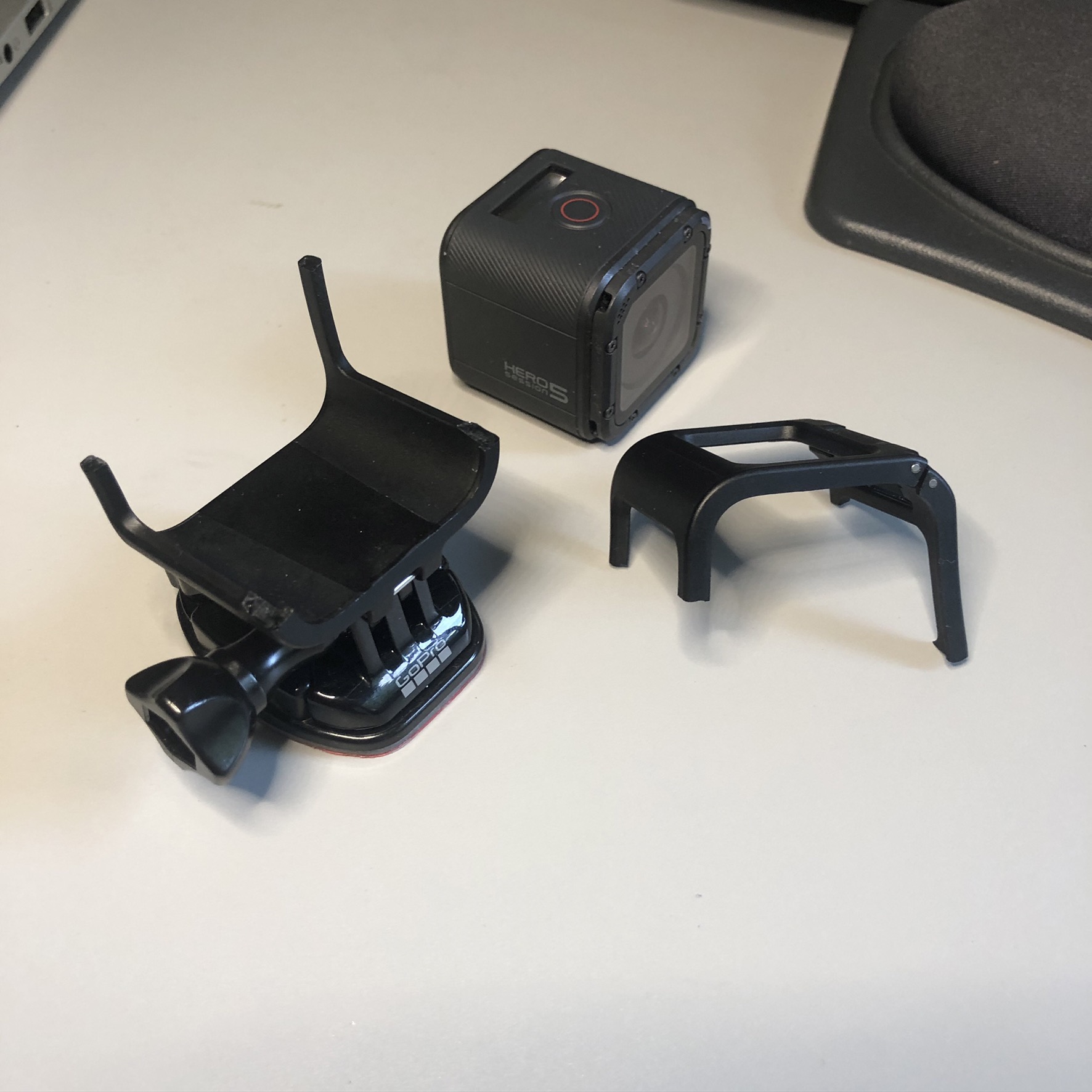
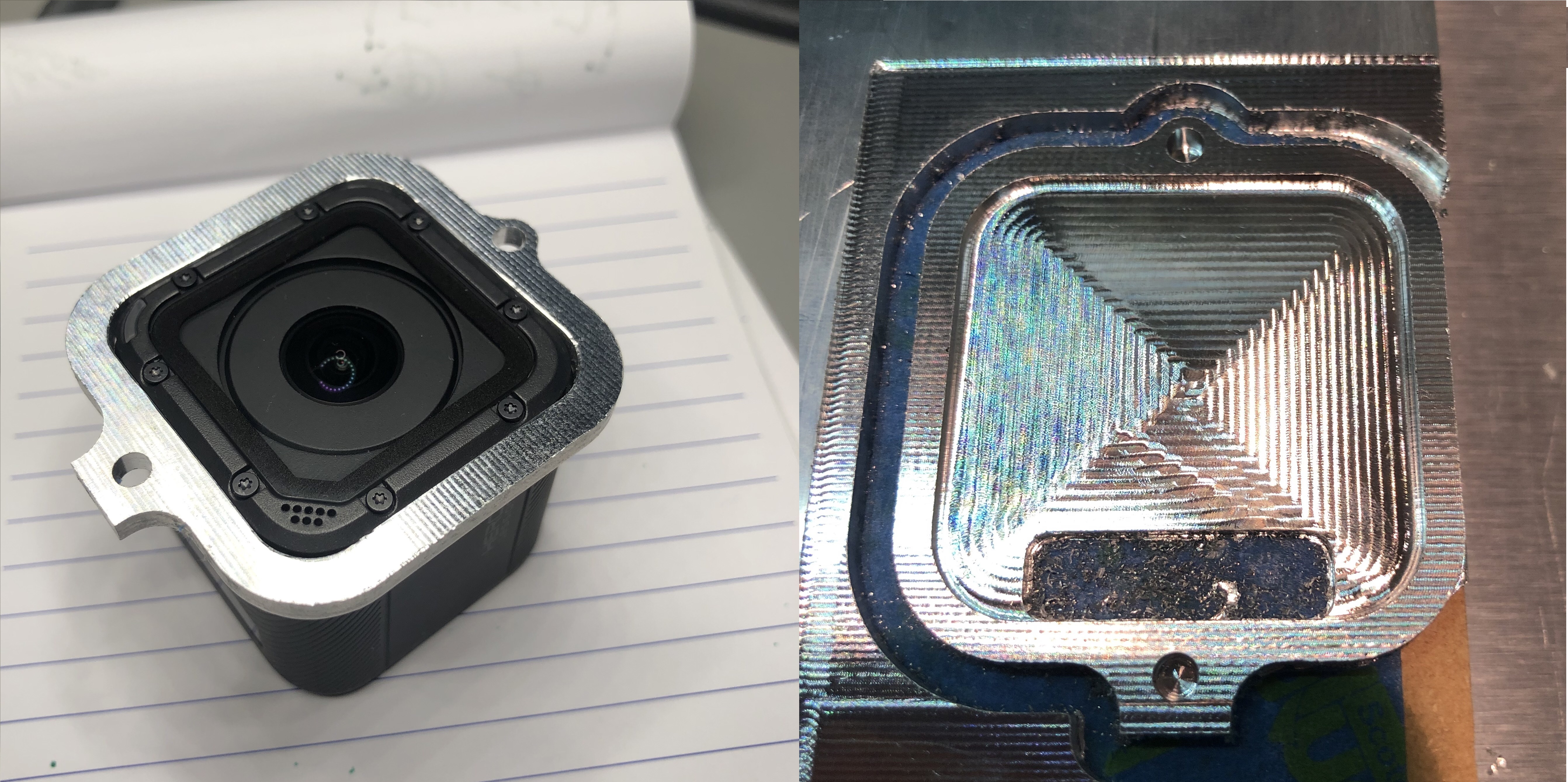
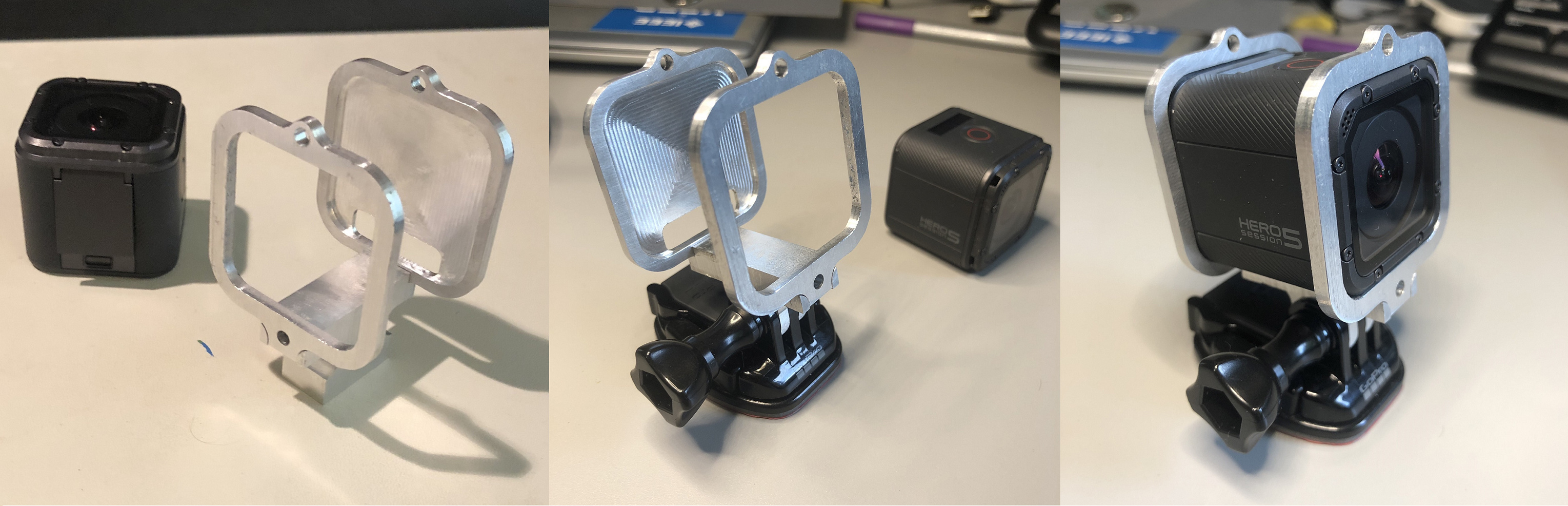
I have a GoPro Session 5 that is a great outdoor camera, but along with outdoor adventures come outdoor bumps and crashes. One of those “incidents” resulted in destruction of the mount for the camera. Unfortunately GoPro replacements are expensive (and the same ruggedness) and my willingness to trust 3rd party housings with my camera (and the footage!) is low. Nomad 883 Pro and Fusion 360 to the… rescue!?!
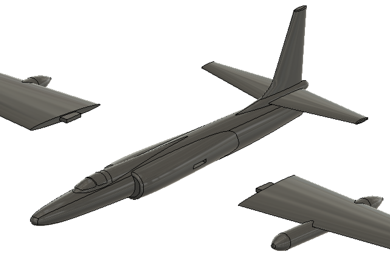
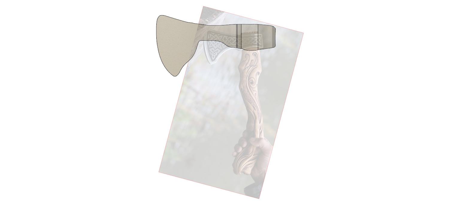
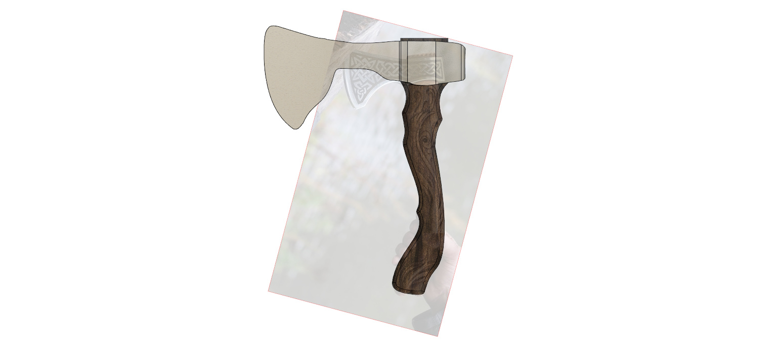
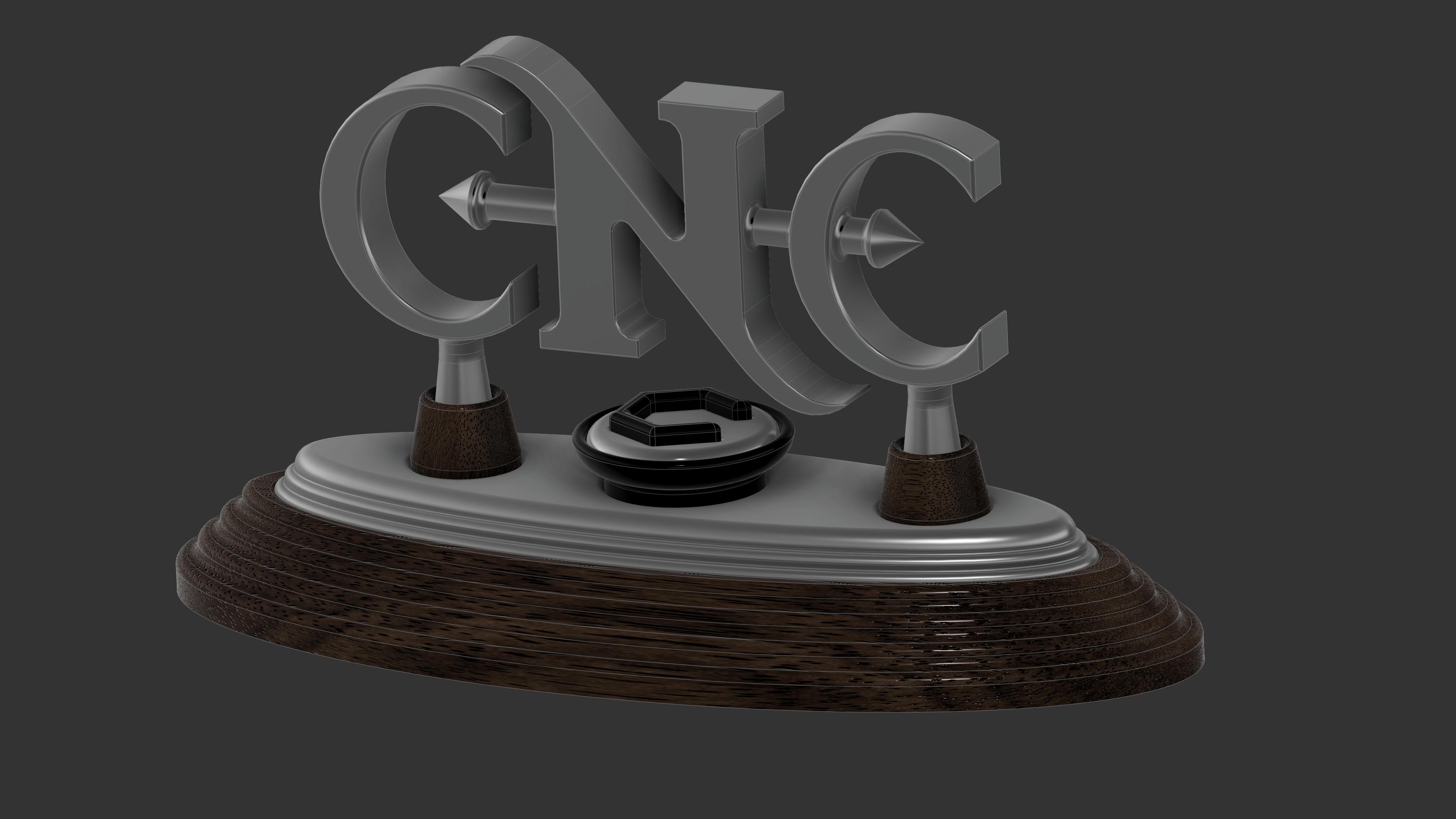
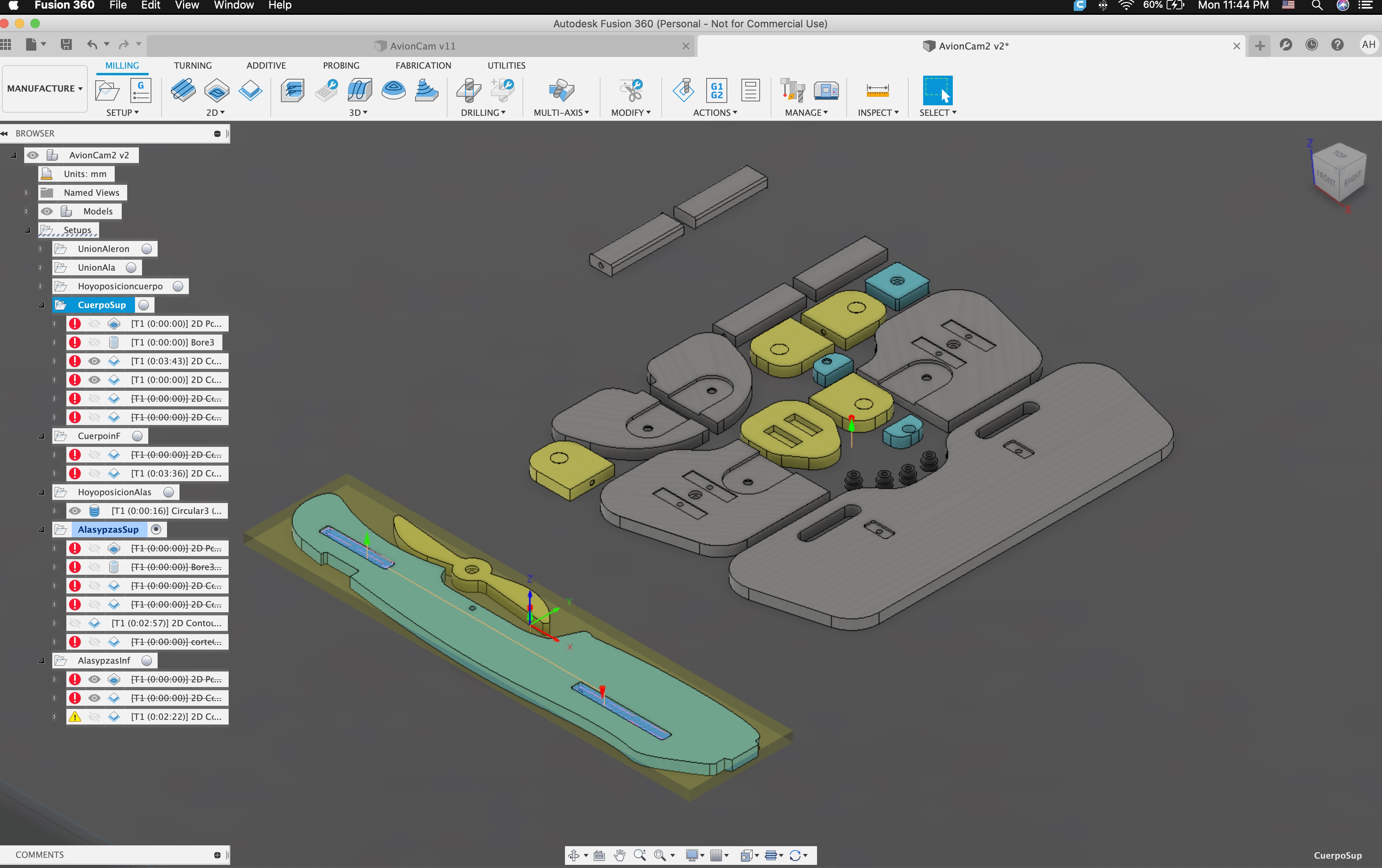
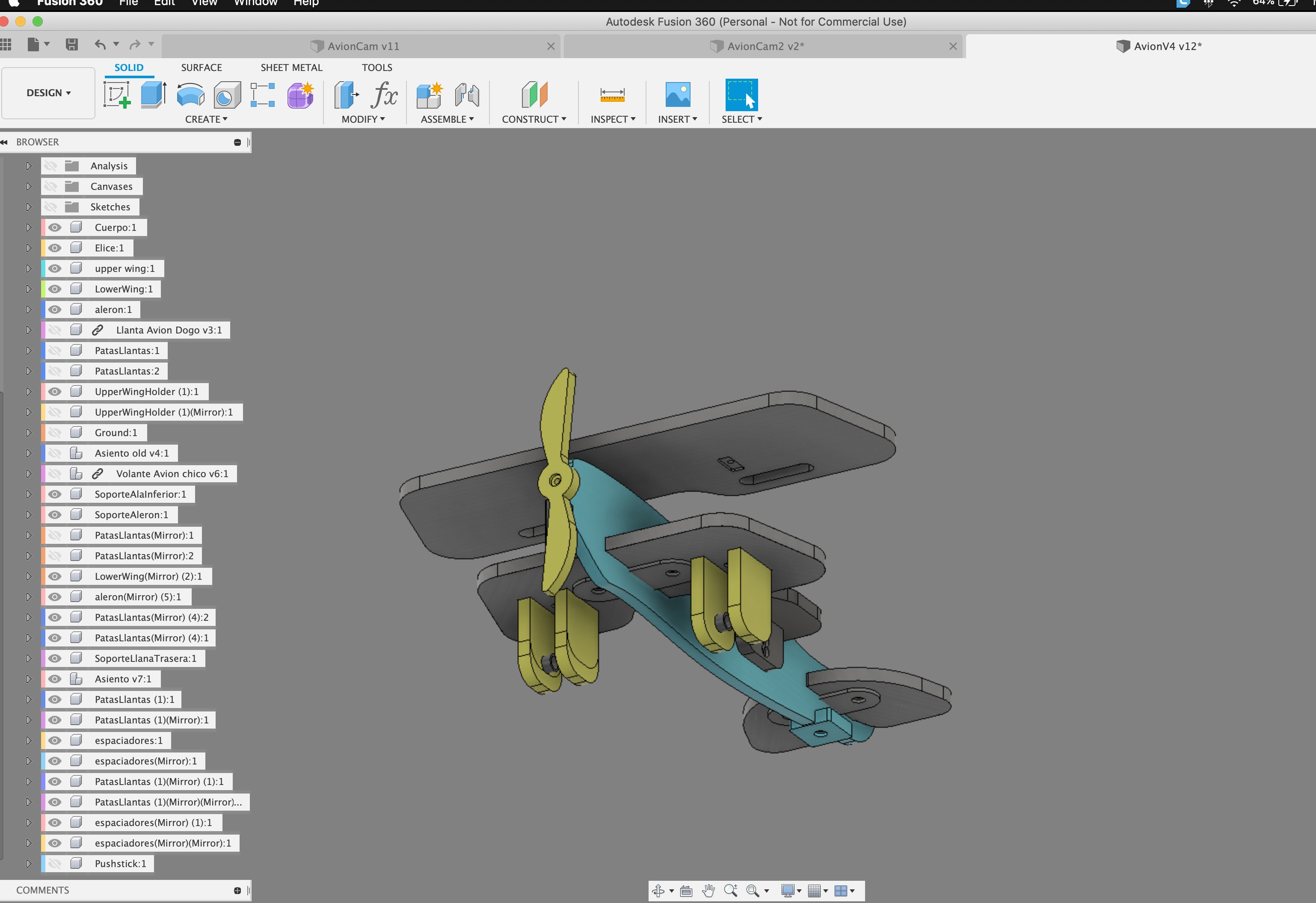
The CAD/CAM

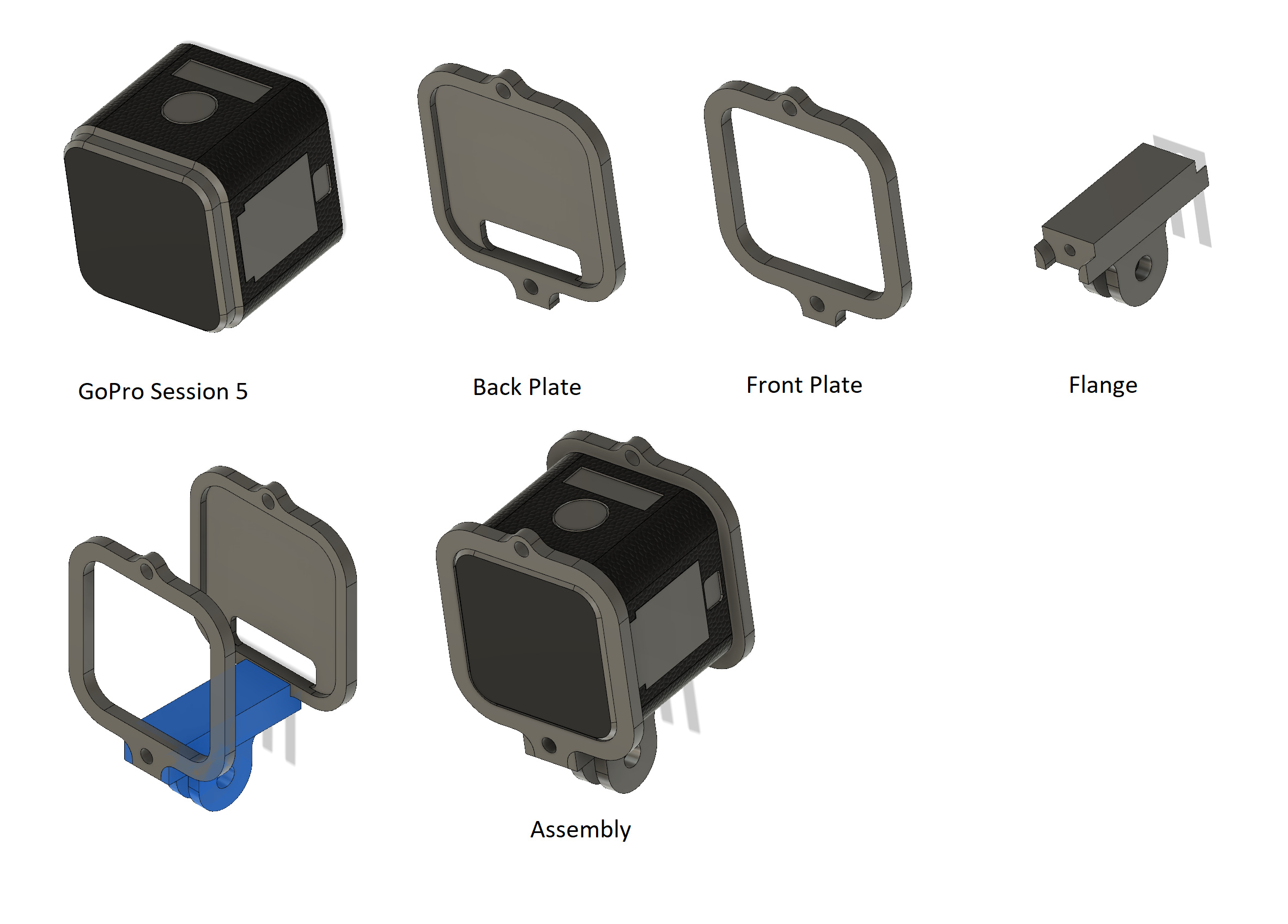
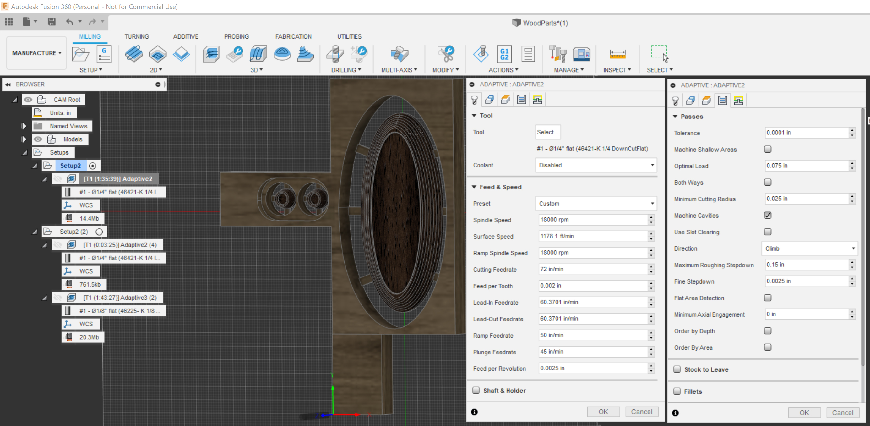
Off to Fusion CAD/CAM we go… This took some precision measuring of the camera to model but fortunately GoPro seems believe in using round numbers so even where my measurements weren’t spot on rounding it to the nearest whole mm worked well. Precision was definitely one of the driving factors as having a camera rattling around (or worse leaping out of the mount) would be a big problem. By default this was going to have to done in aluminum for ruggedness.

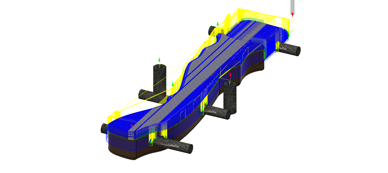
Some ?Clever? CAM Things
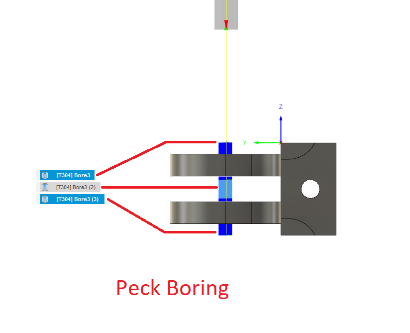
Peck Boring

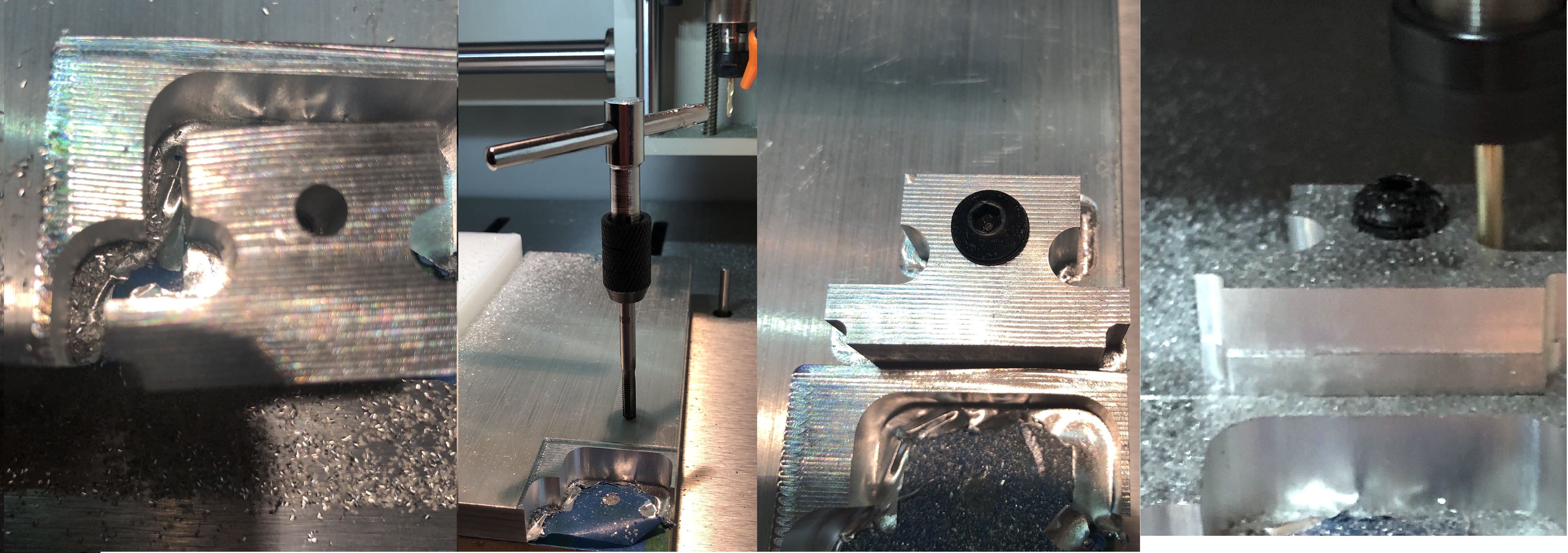
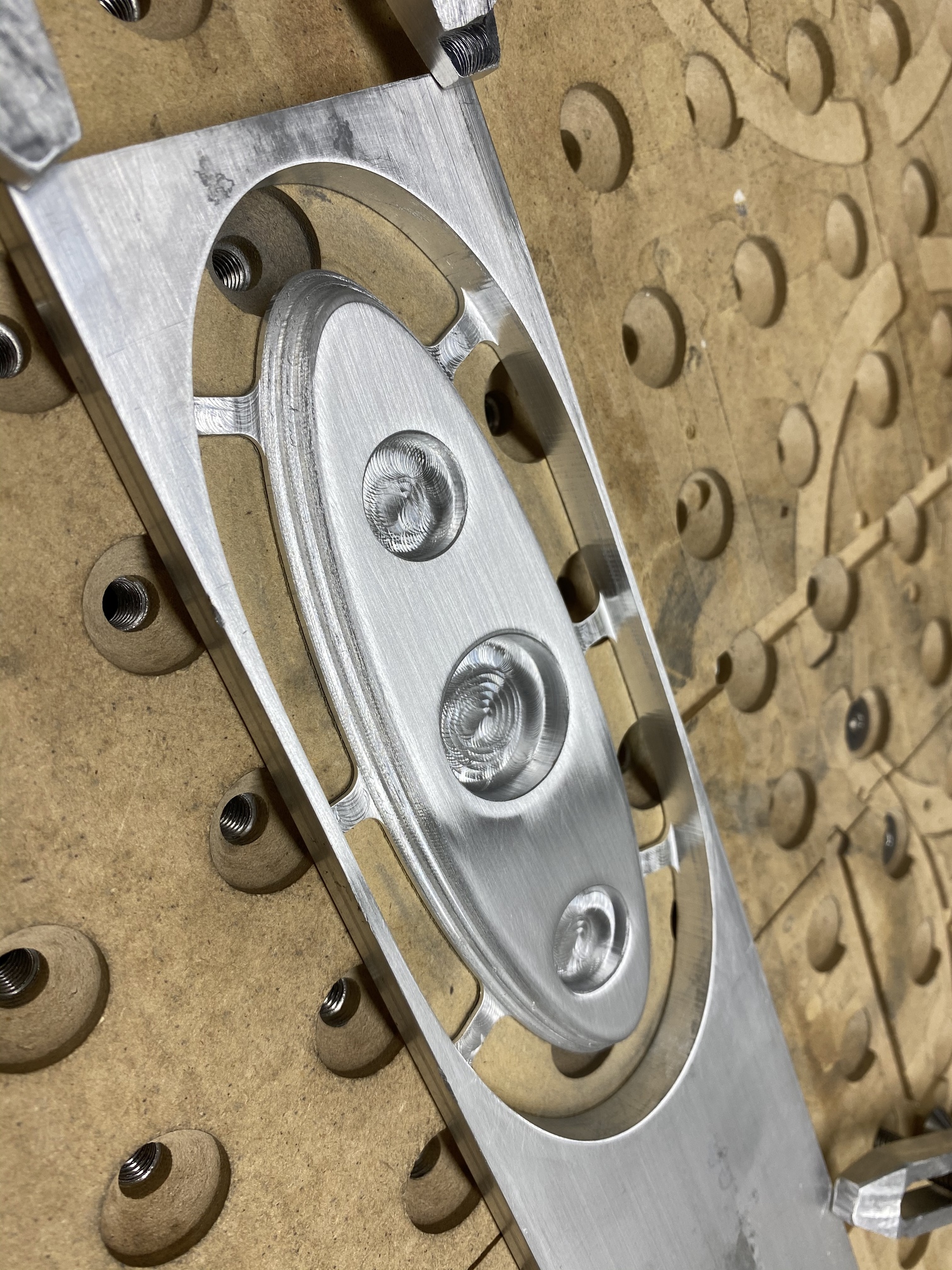
The hole for the mounting screw in the Flange section was relatively deep and narrow so I created what I’ll call “Peck Boring” where I used multiple bore operations to bore then retract so the chips could be cleared by the air blast as the hole was created.
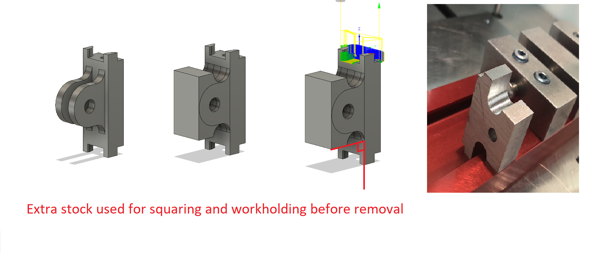
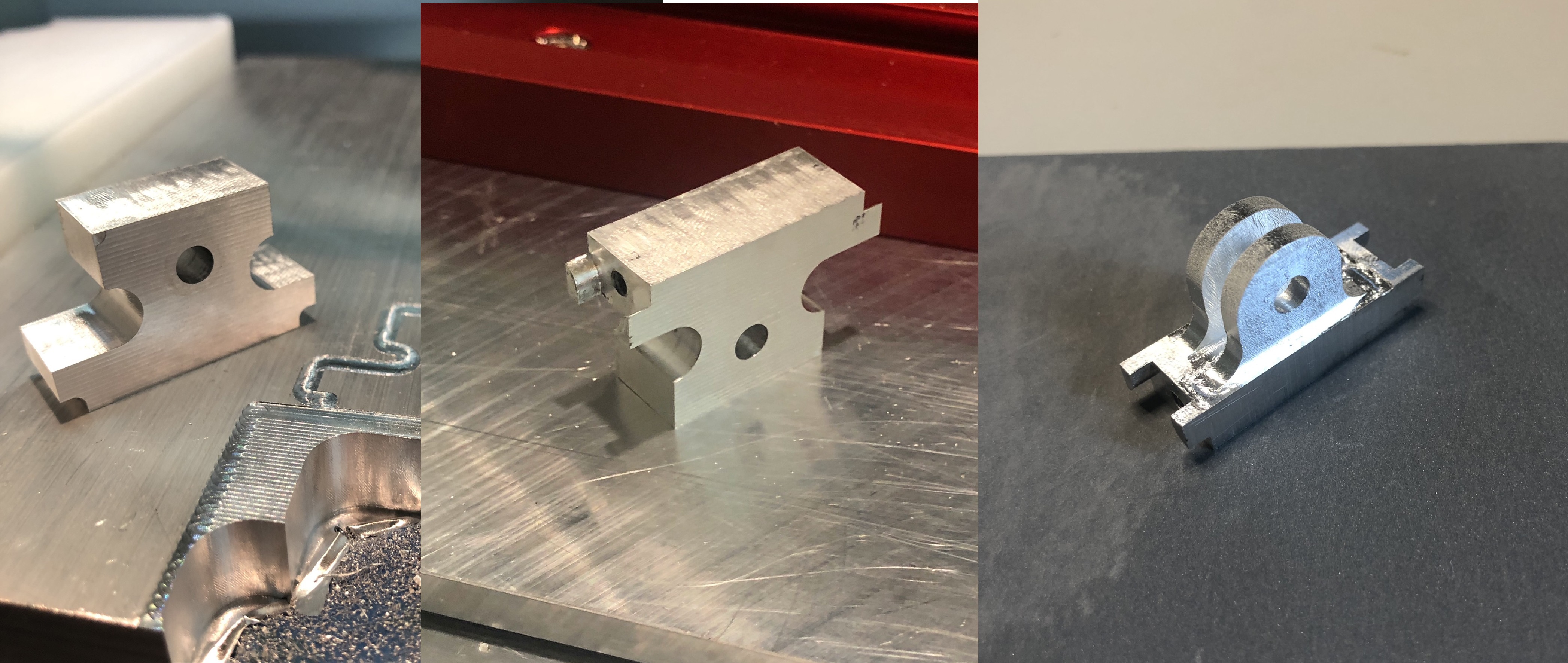
The False Bodies

One of the things I recognized early on was some of the end machining on the tall narrow Flange section meant there was going to be very little material for that Nomad vise to hold onto and securing and squaring with precision would be a challenge. I do not want a repeat of the part squirm that destroyed a brand new TiCN end mill a couple of weeks ago. So to combat that I added some extra material in the form of square bodies on the side that had the rounded ears that would allow me to use the vise bottom for additional stability and would make it much easier to square up vertically. These bodies would later be removed and milled away. I could go on and on about the steps involved but the following sequence gives an idea.

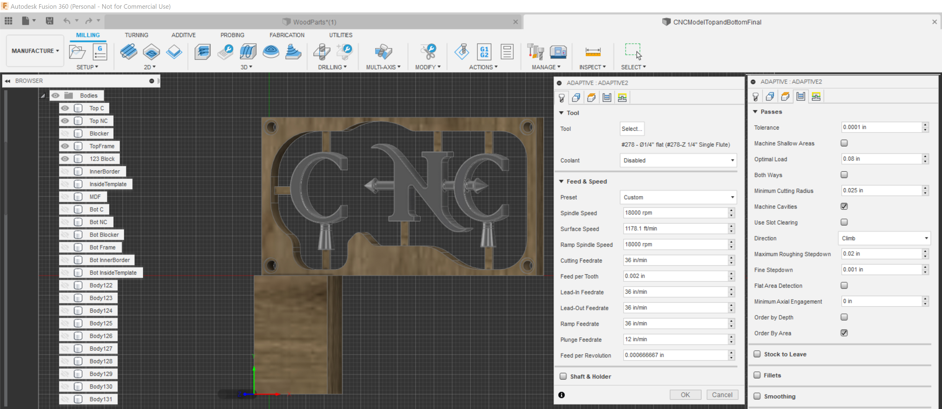
The Front and Back plates

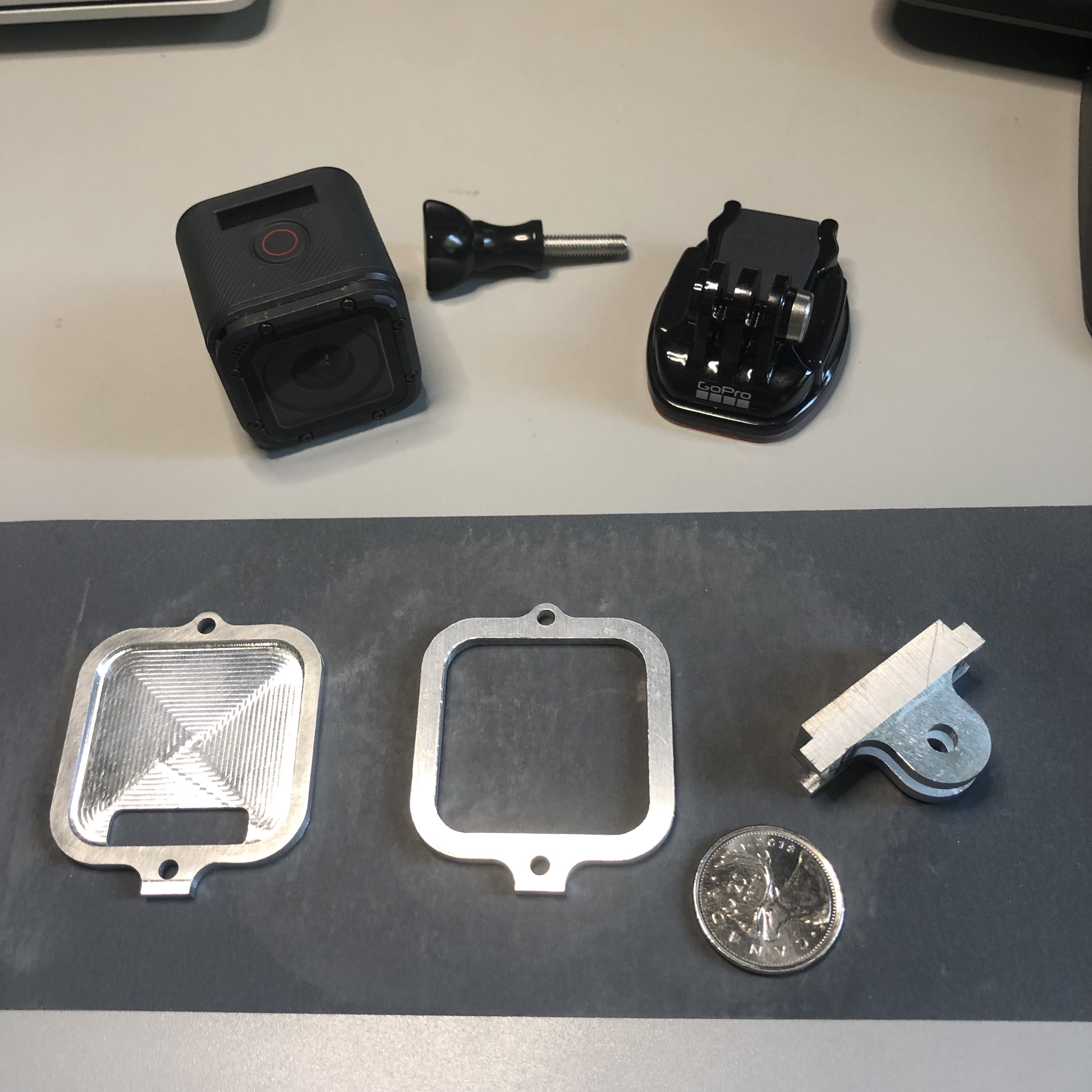
The front and back plates were simple 2.5D operations and were taken care of in short order. The good news was these fit on the camera perfectly! Measuring twice for the win!

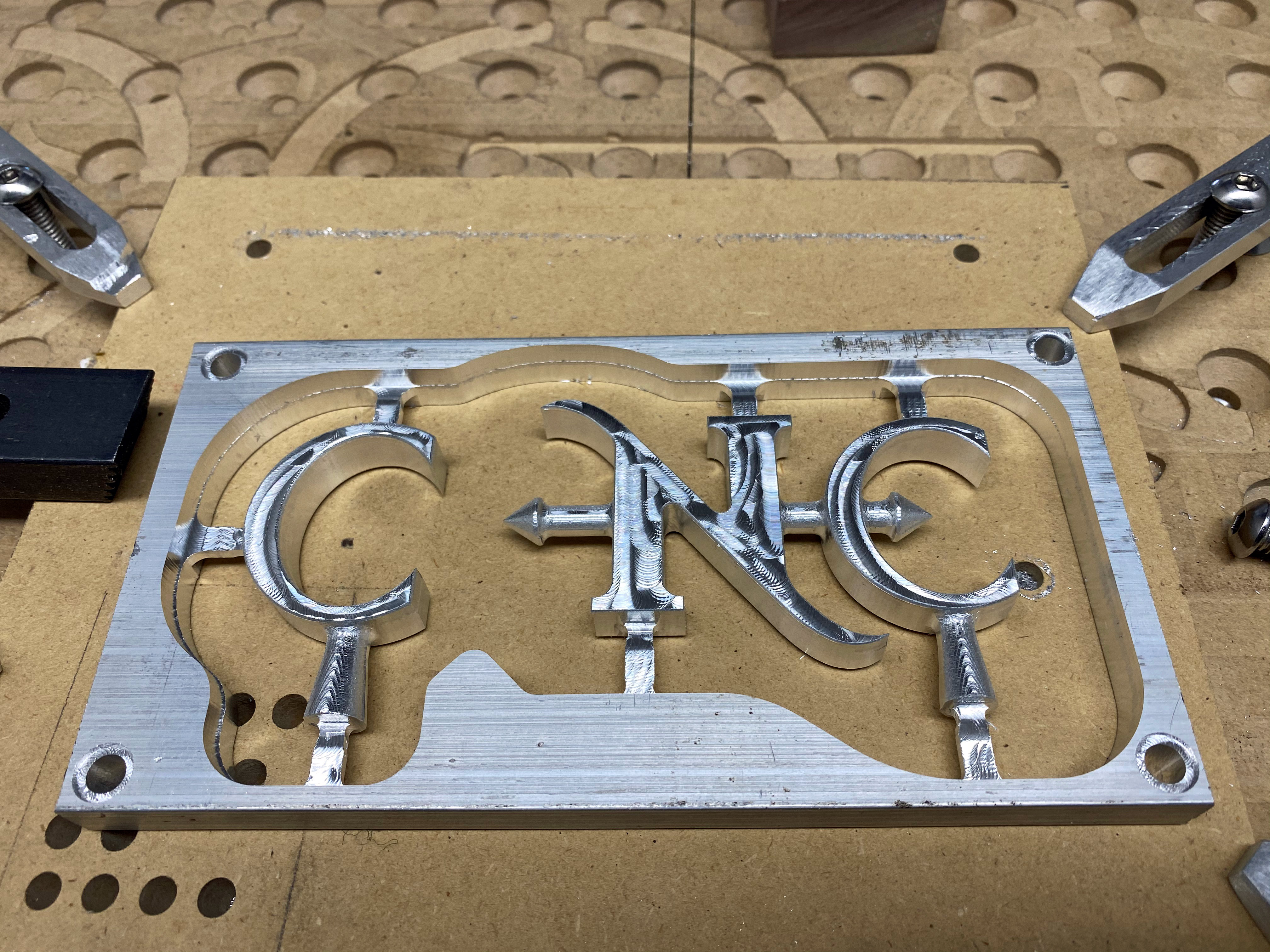
The Mistake and the Fix

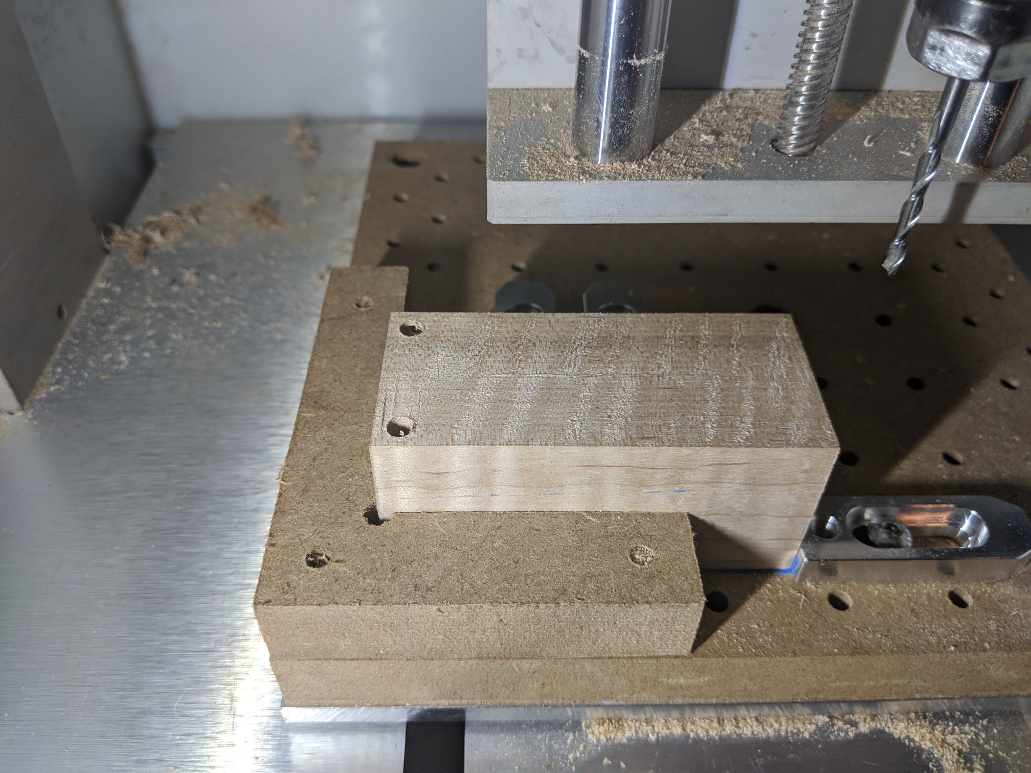
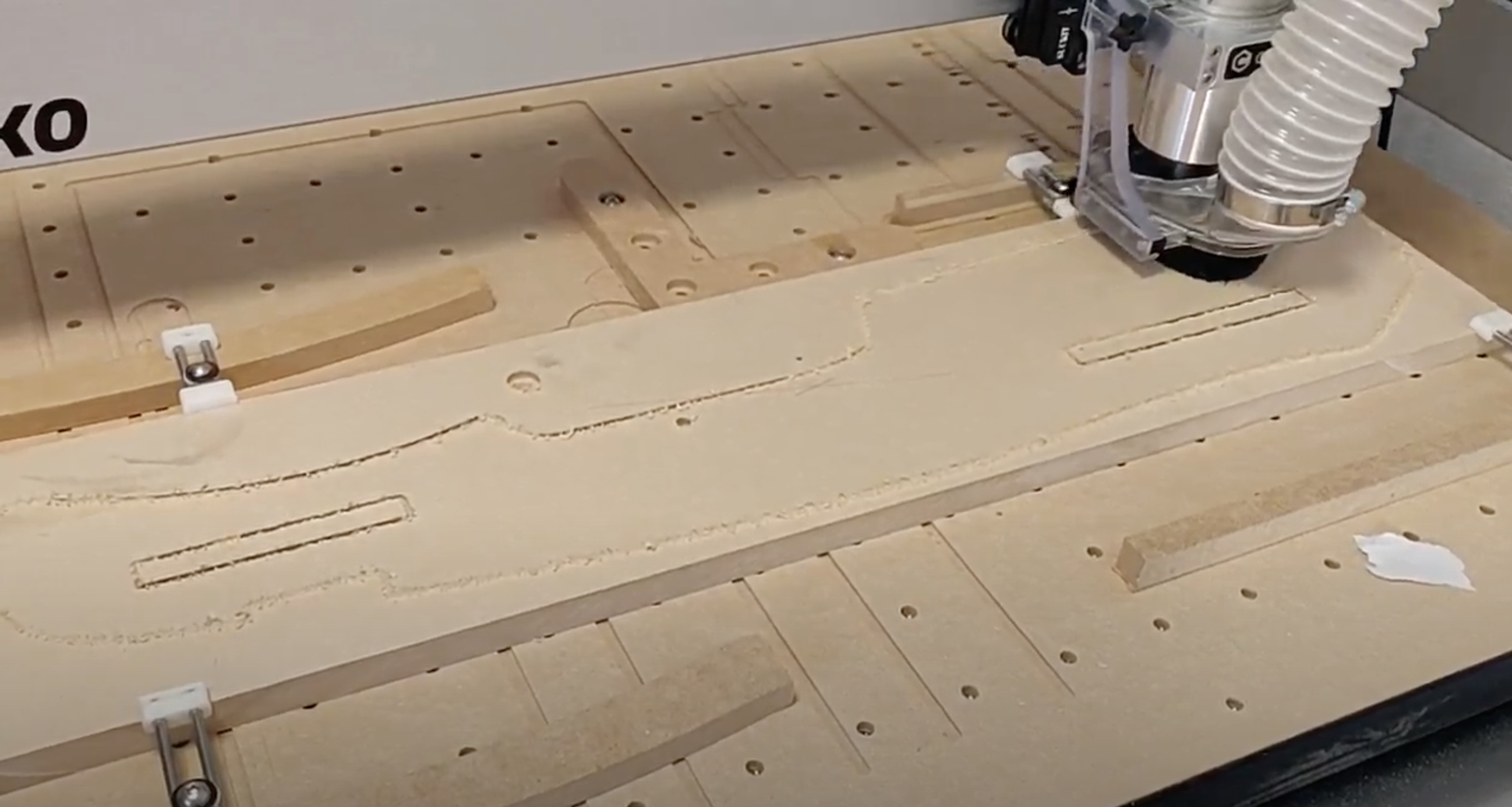
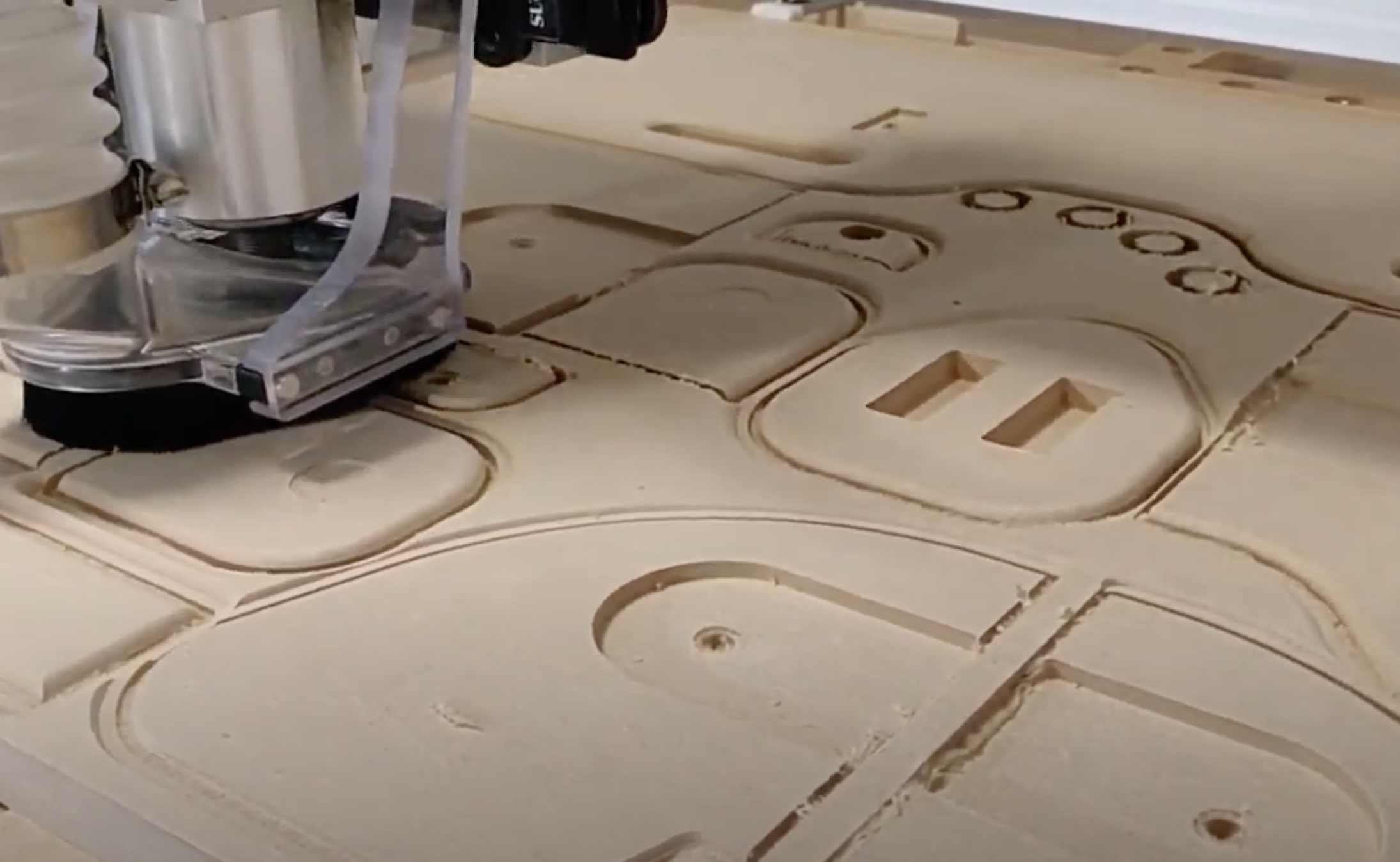
CAM in hand I set up the first operation for the Flange to cute the main shape out of 1/2" (12.7mm) aluminum plate. Went with my trusty CA glue and blue masking tape approach and away I went, pushing things up to 170% feedrate override as I had cleverly (hahaha) left 0.2mm of stock to leave at the bottom to keep it in place. I should have slowed things down as I reached the bottom but got distracted at the perfect moment and “pop”! off the part flew. The good news was the roughing was basically done. The bad news was I had 0.3mm of extra stock to remove on every side of the part!!!

A regroup and I bored and tapped a hole in the aluminum plate and screwed the part down onto it, carefully squared and edge found the part, and contoured the excess stock off the sides. Saved!

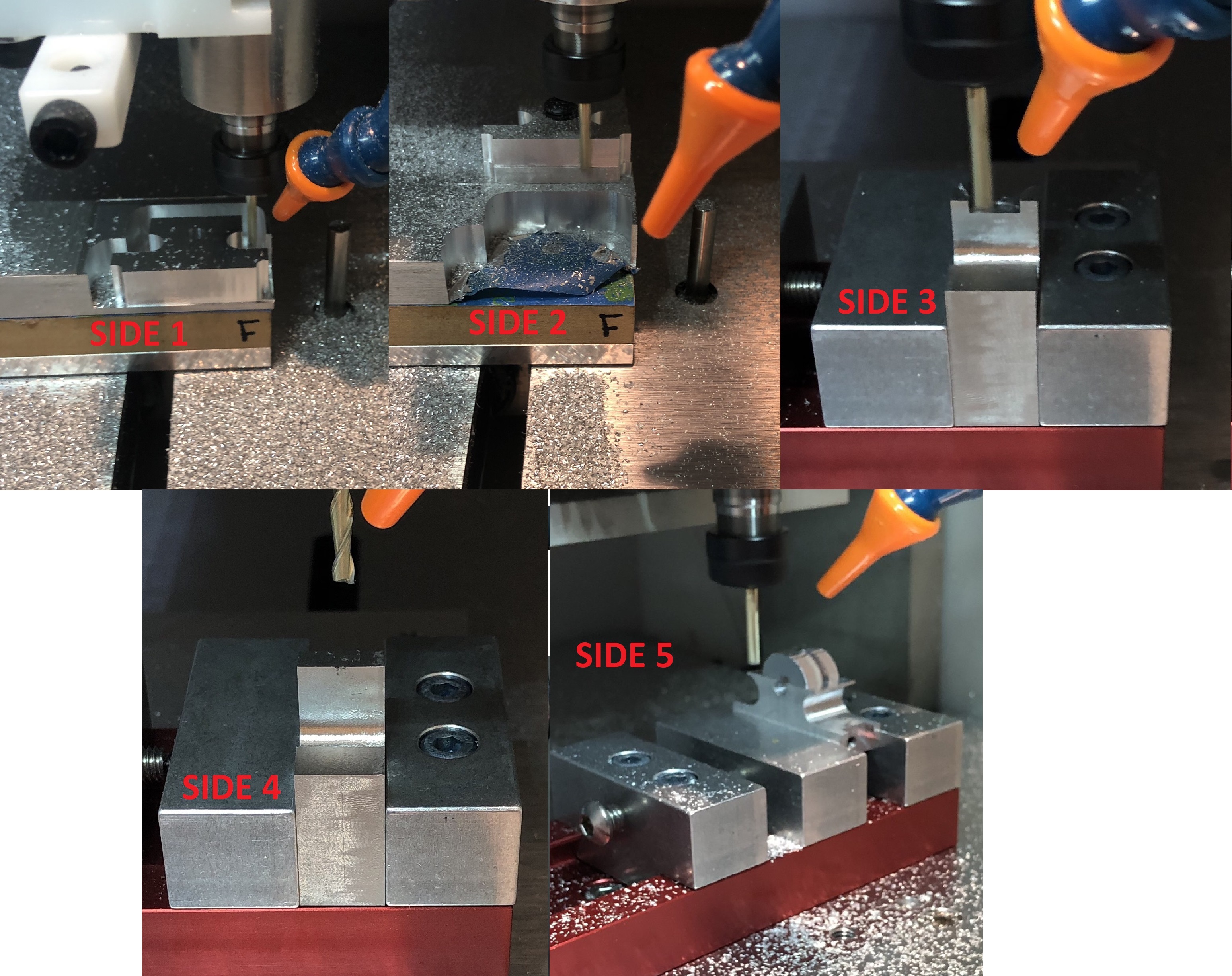
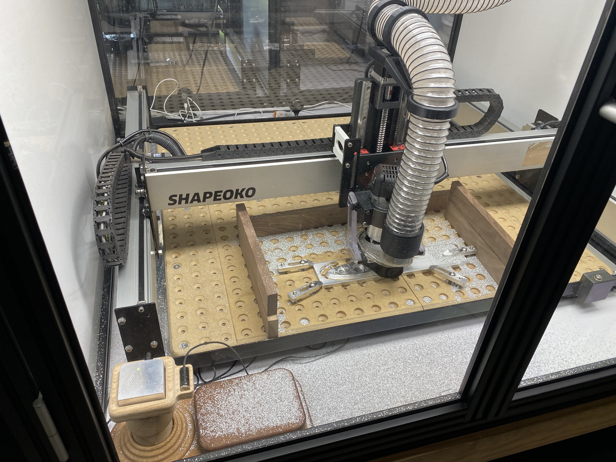
And now for some Setups

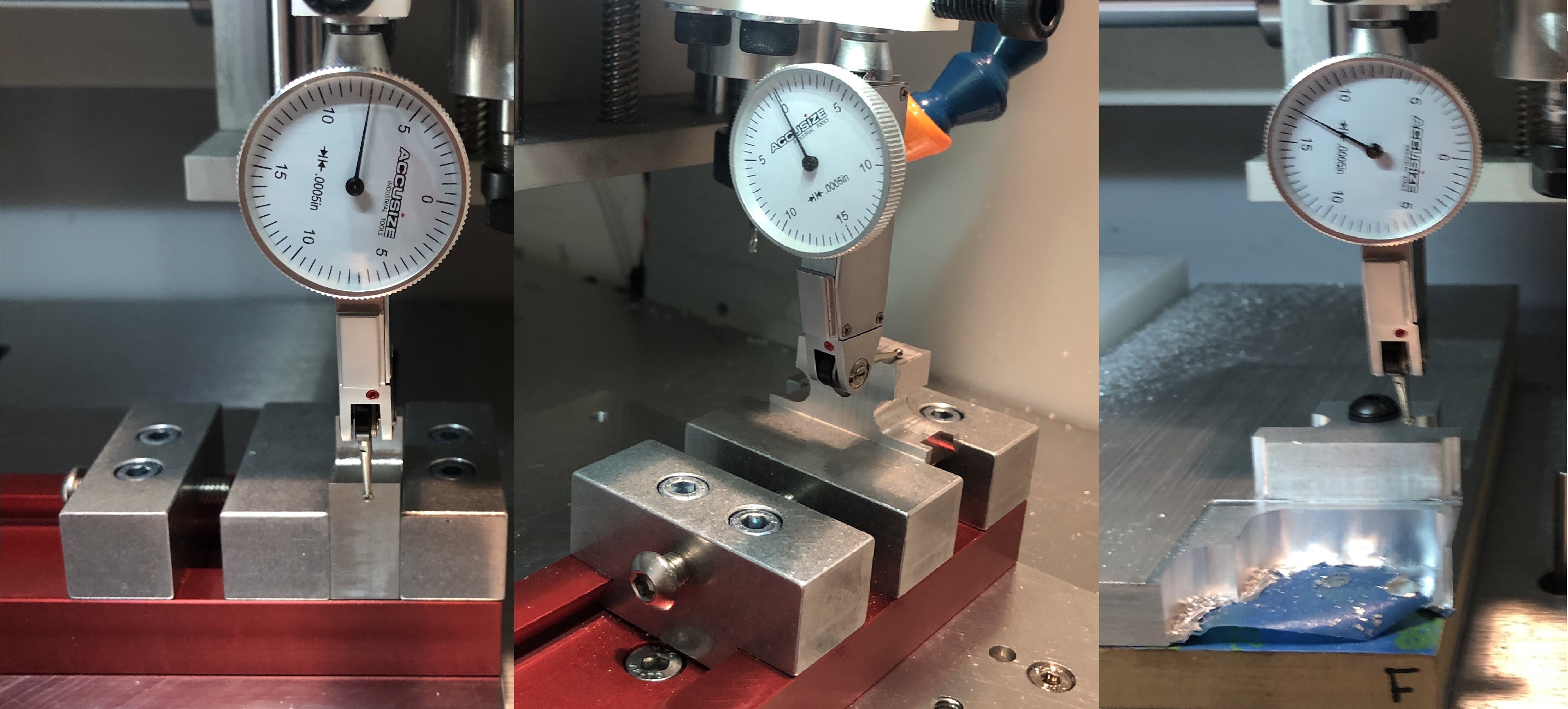
This Flange really pushed me on setting up square, getting the WCS zero in places on the stock/model that I could edge find on, and making sure the part didn’t move around. Fortunately I didn’t make too many mistakes!

Check check check double check triple check

On every setup where it was required, before I moved the part and lost the WCS zero from the operation I checked as much as possible in case I had to go back and adjust something.

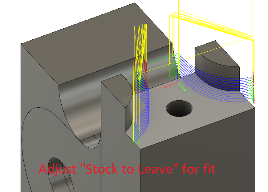
I set up the CAM for critical areas so I could go back for a second/third pass to adjust the size by milling off slightly more material by using the “Stock to Leave” function in F360. This HAD to be done without disturbing the WCS zero from the previous OP. Fortunately I got it pretty much right on the first time!
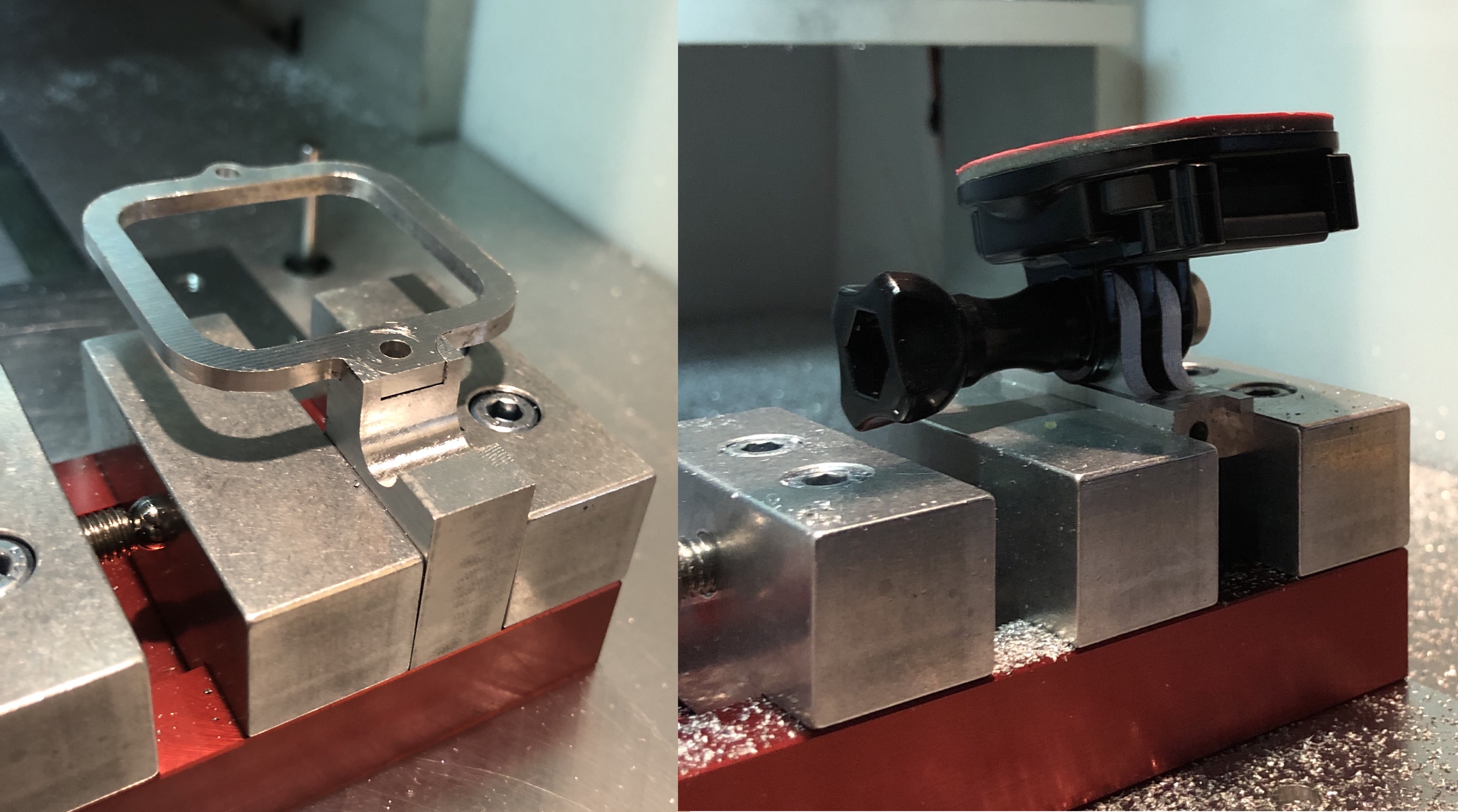
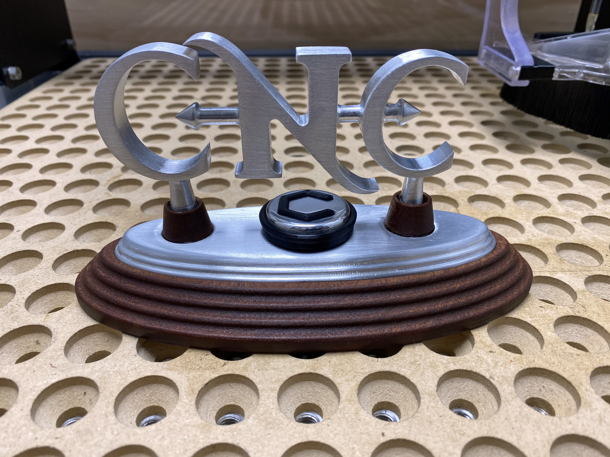
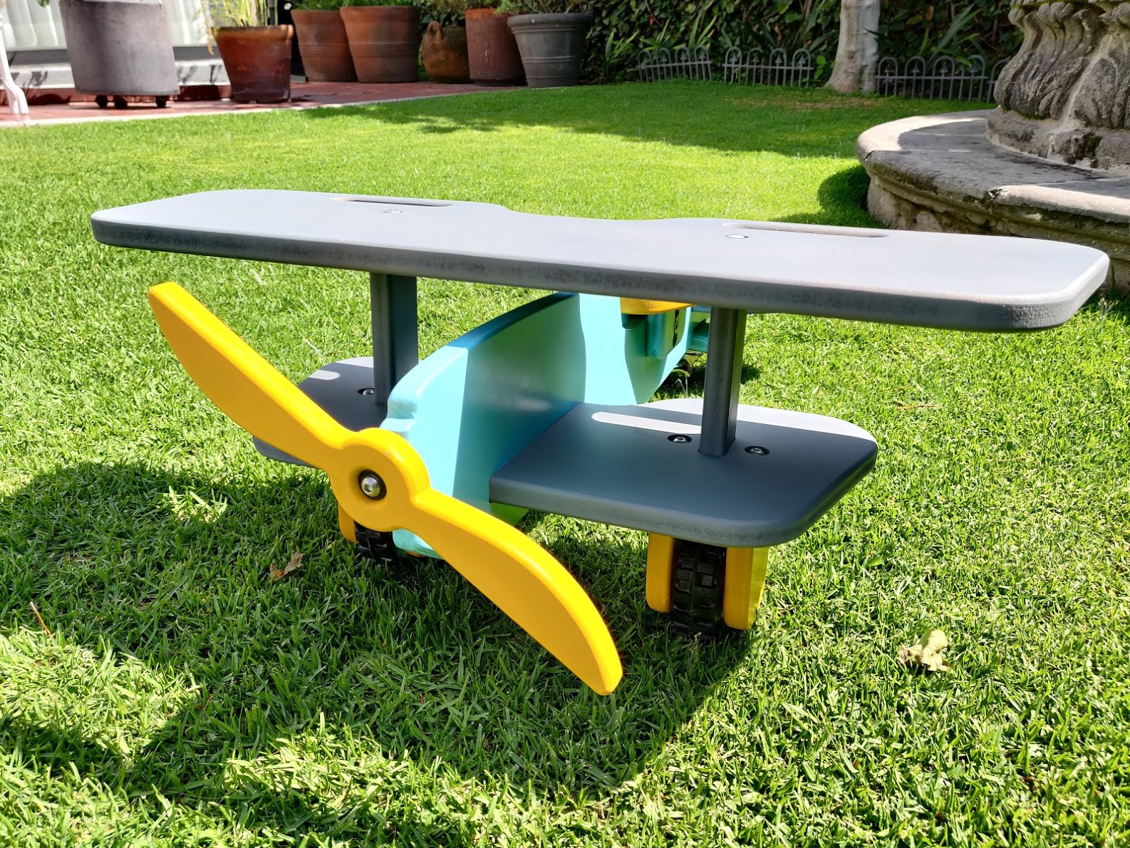
And… almost Done!

Unfortunately the bottoming tap and stainless steel screws did not arrive yet for installation to hold the front and rear plates to the flange but the test fit is all good. Machining done!

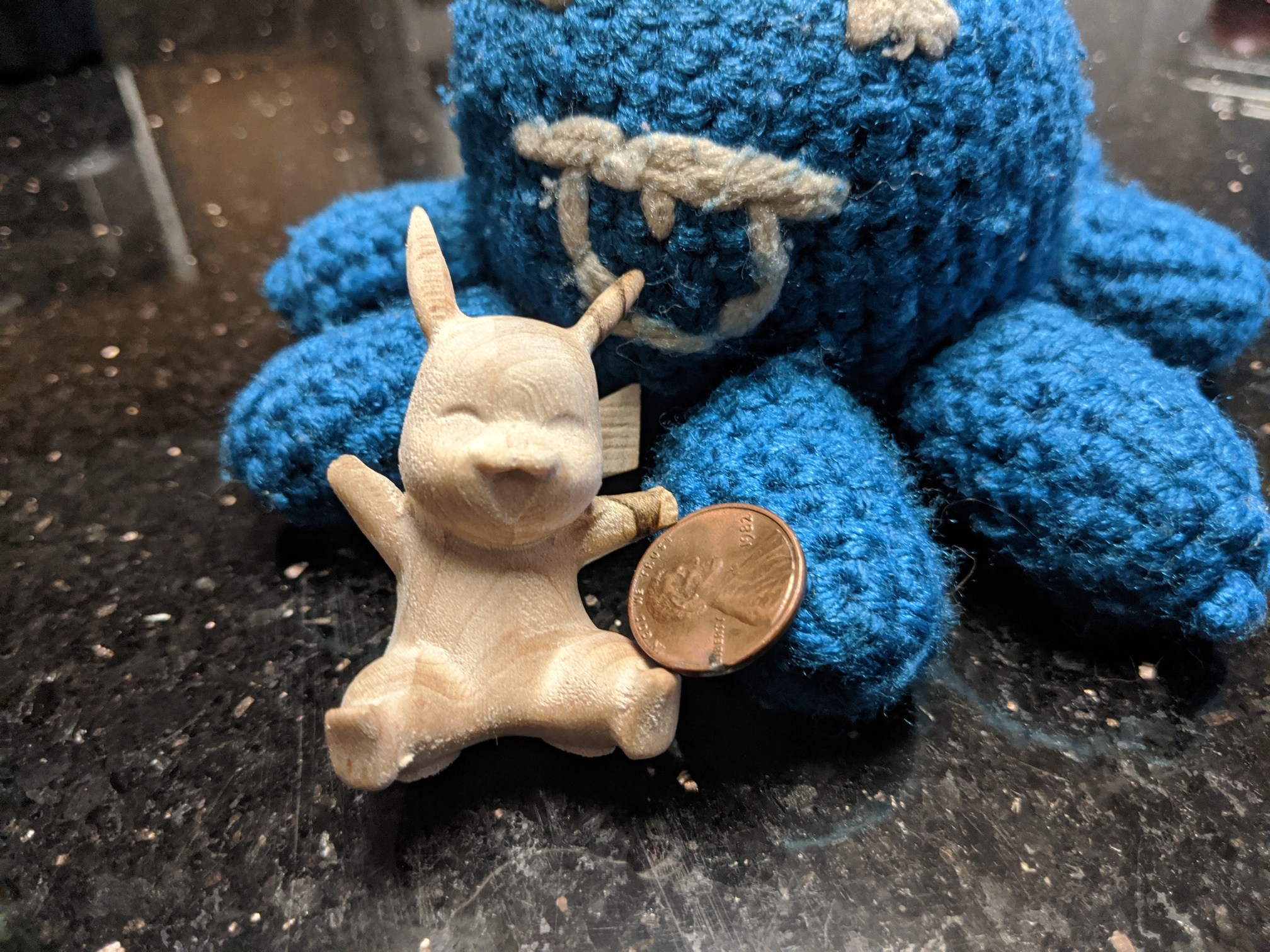
Quarter Coin - same size as a US Quarter for size reference

Had fun trying a few new things - hope somebody finds something of use in this!

As always files on CutRocket!

15 Likes

Friends,
I was not sure if I was going to be able to finish this piece on time, I am in South Florida and Isaias was keeping me busy with the Hurricane shutters and storm preparations. But luckily we were spared any serious impact and the power did not go out so I was able to complete the project on schedule.

I would like to submit for consideration, this 10 piece creation depicting the two secrets to a lifetime of fulfillment and happiness.
The ingredients are 6061 Aluminum, Mahogany and black PLA Plus with a 1/4" sealed bearing.
The letters are a 2 sided carve from 1/2" Aluminum, the base is from 3/8". The center Carbide 3D logo is printed with PLA plus with a polished aluminum insert. The letters and base are hand sanded and polished to 5000 then backed down to a brushed 400 grit surface.
Of course I can not submit an entry without a spinner, so I included the YouTube video link below to give an example.
Youtube Video

Below is the Fusion 360 link for viewing the models in the 3d web viewer, and also a link for download.
Fusion 360 Web Viewer

And a link to the Cutrocket files.
Cutrocket Link


And some of my speeds and feeds from Fusion. I try to design my projects toolpaths to use 1 tool if possible, and use an adaptive toolpath with a dual setup in mind. Mild force on rough carving and then ultra fine settings on the beveled edges. My fine settings are .001 for Aluminum and .0025 for wood. This should leave you with almost no finishing work and no ball nose end mill or tool changes are needed.

15 Likes

I’m glad I set those deadlines to midnight PST, which translates to 9am next morning here, so each time I get to wake up and see some great last minute entries :slight_smile:

Voting is now open!

5 Likes

@moakley8 Did you ever finish the U2? I’d love to see actual pictures instead of just the rendering.

yes i did but it was given away to someone. And i dont have pics
I was hired to model it so that it could be made. I made 1 just to prove it could be done.