Think @Buhbuh scared everyone off with that impressive entry. Have a plan, don’t have much time!
On the flip side… if I could win a Zplus I would be one more step closer to a Shapeoko. Or a hybrid Z plus Nomad…
Think @Buhbuh scared everyone off with that impressive entry. Have a plan, don’t have much time!
On the flip side… if I could win a Zplus I would be one more step closer to a Shapeoko. Or a hybrid Z plus Nomad…
Yes they do local lockdowns here, but I don’t know what the threshold is. Last I heard of was near Frankfurt, not a surprise.
Hope France will recover control soon and get back to lower cases per day.
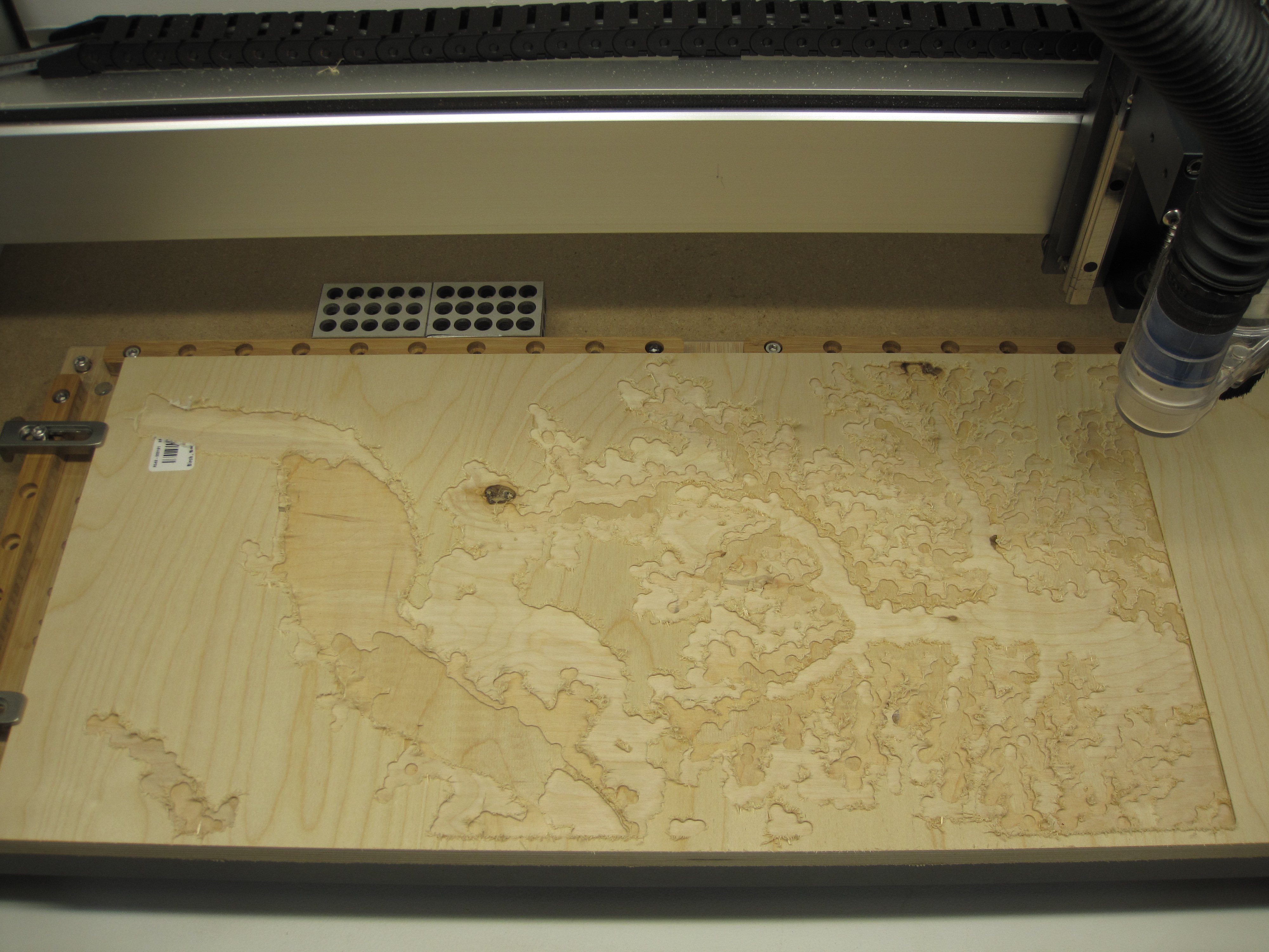
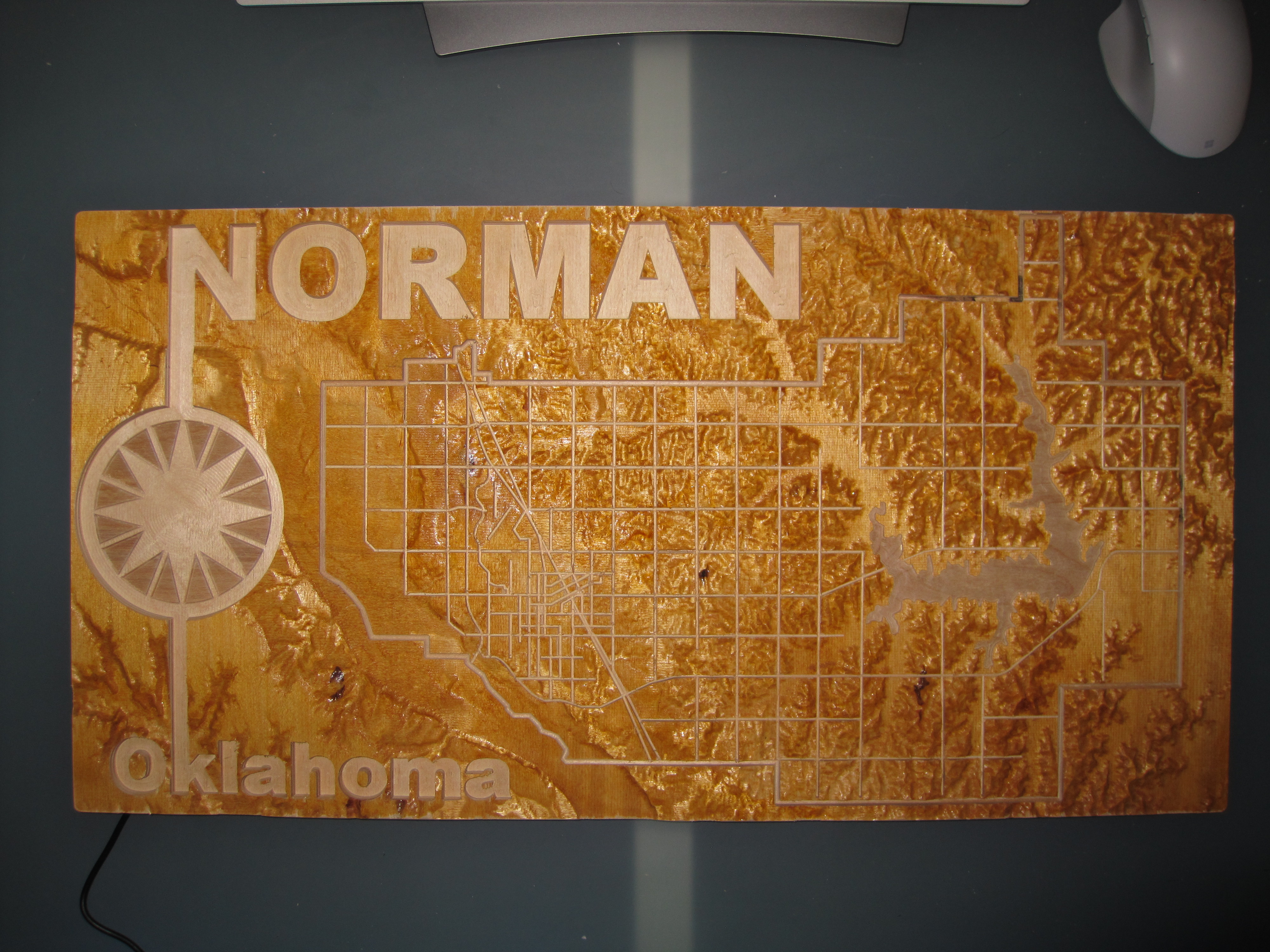
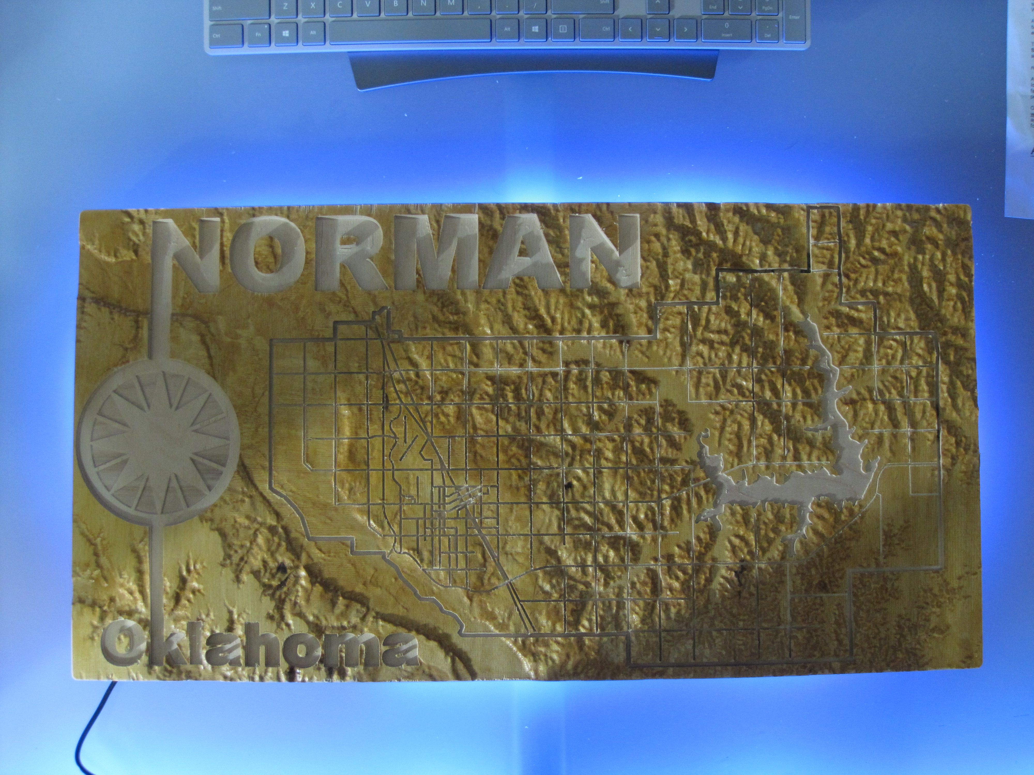
My Town Map
I’ve been building this idea in my head for awhile now, community challenge #13 was just the push I needed to get started.
I live in Norman Oklahoma, and ever since seeing Carbide 3D’s demo on how to make a topographic 3D model I’ve had this idea to make a map of my home town.
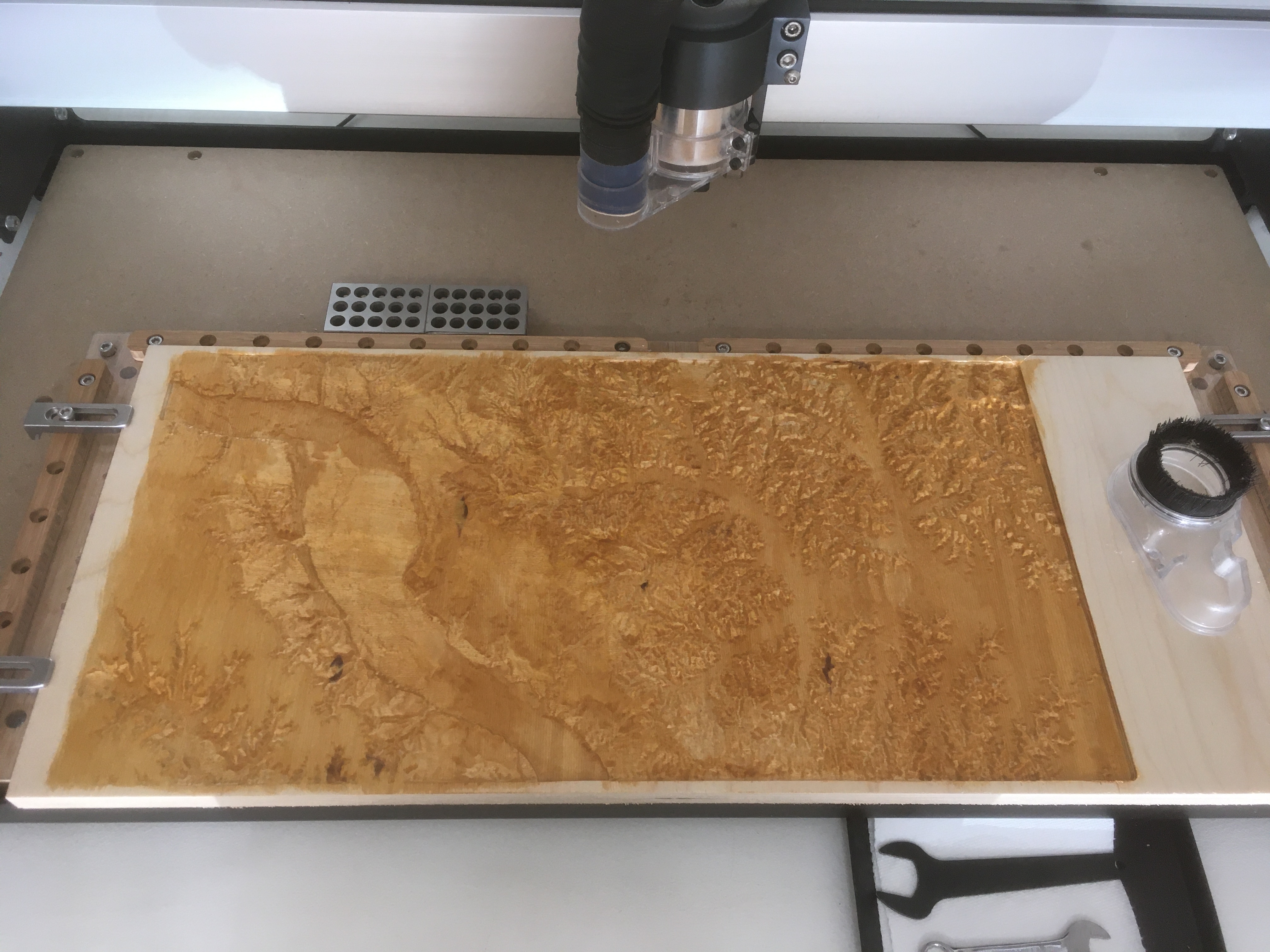
I started with Tangrams Heatmap which gave me the elevation. I then had to overlay a roadmap of Norman to add the (major) streets. Funny fact, Oklahoma is pretty flat, and the Tangrams heatmap informed me the difference in the highest and lowest points of Norman Oklahoma is 60 feet.
Carbide Create was used to combine this information into a model.
I used the background image feature to put the street map on top of the heightmap. I then pathed each of the major streets (by hand) using the Polyline drawer.
The “Norman” and “Oklahoma” were originally text objects, but then they were combined with a design from the Norman city flag to create that design.
I broke the toolpaths into 4 jobs, first one was the 3D roughing…
Many hours later, the Shapeoko was done. The final step was to add lights. In the day-dreaming phase of this project I thought about really going overboard with the lighting, but reality was suggesting I just add backlighting.
I really like how it turned out.
(lights off)
(lights on)
(close up - playing with macro lens)
Norman v4.c2d (2.2 MB)
Nice work!
I didn’t realize Oklahoma has topography 

I really like the golden look with that stain, and carving the streets and letters after the relief was done makes its stand out from other topo maps, very well done ! Have you considered selling such maps locally ? (or donating one to city hall  )
)
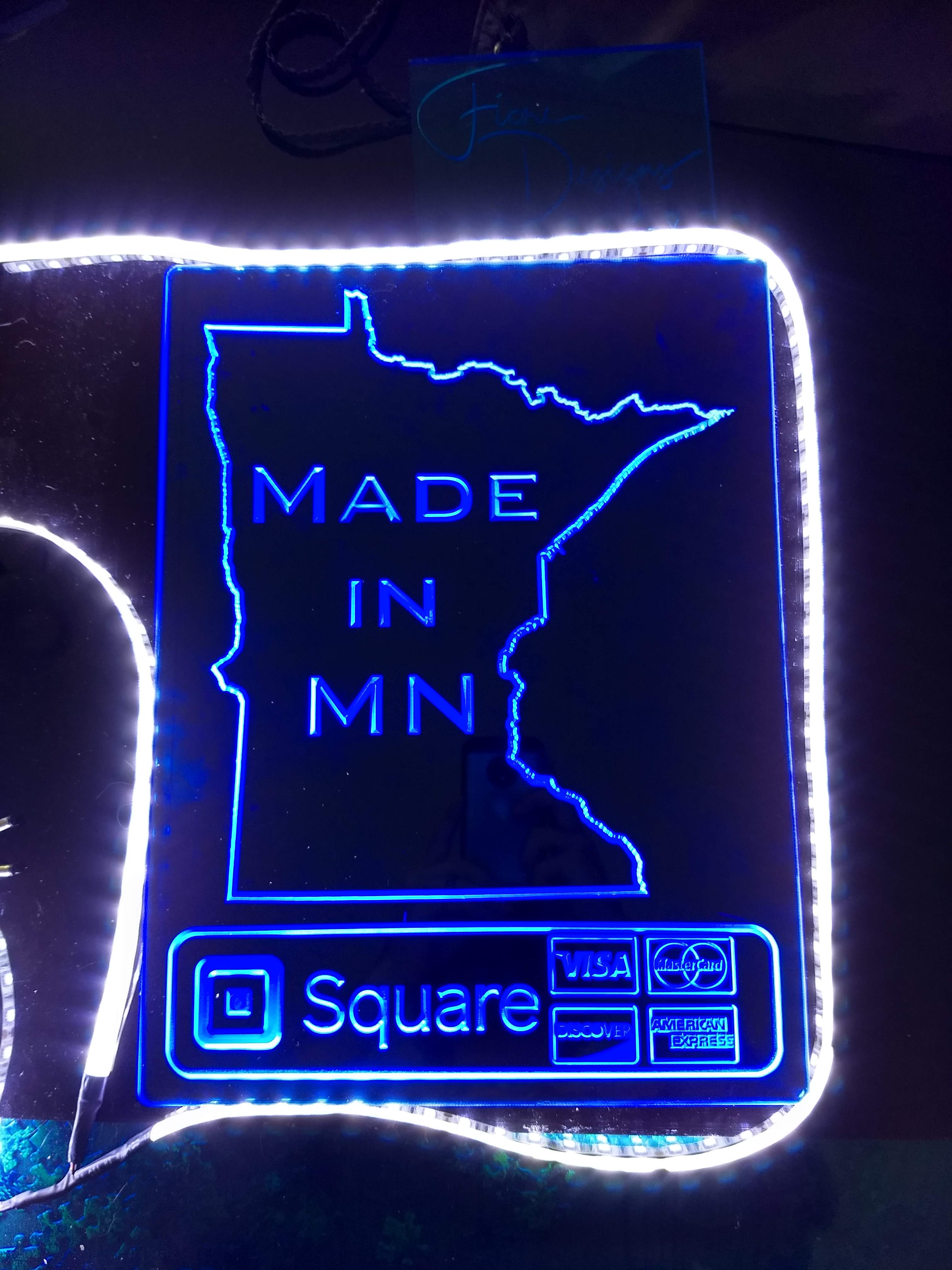
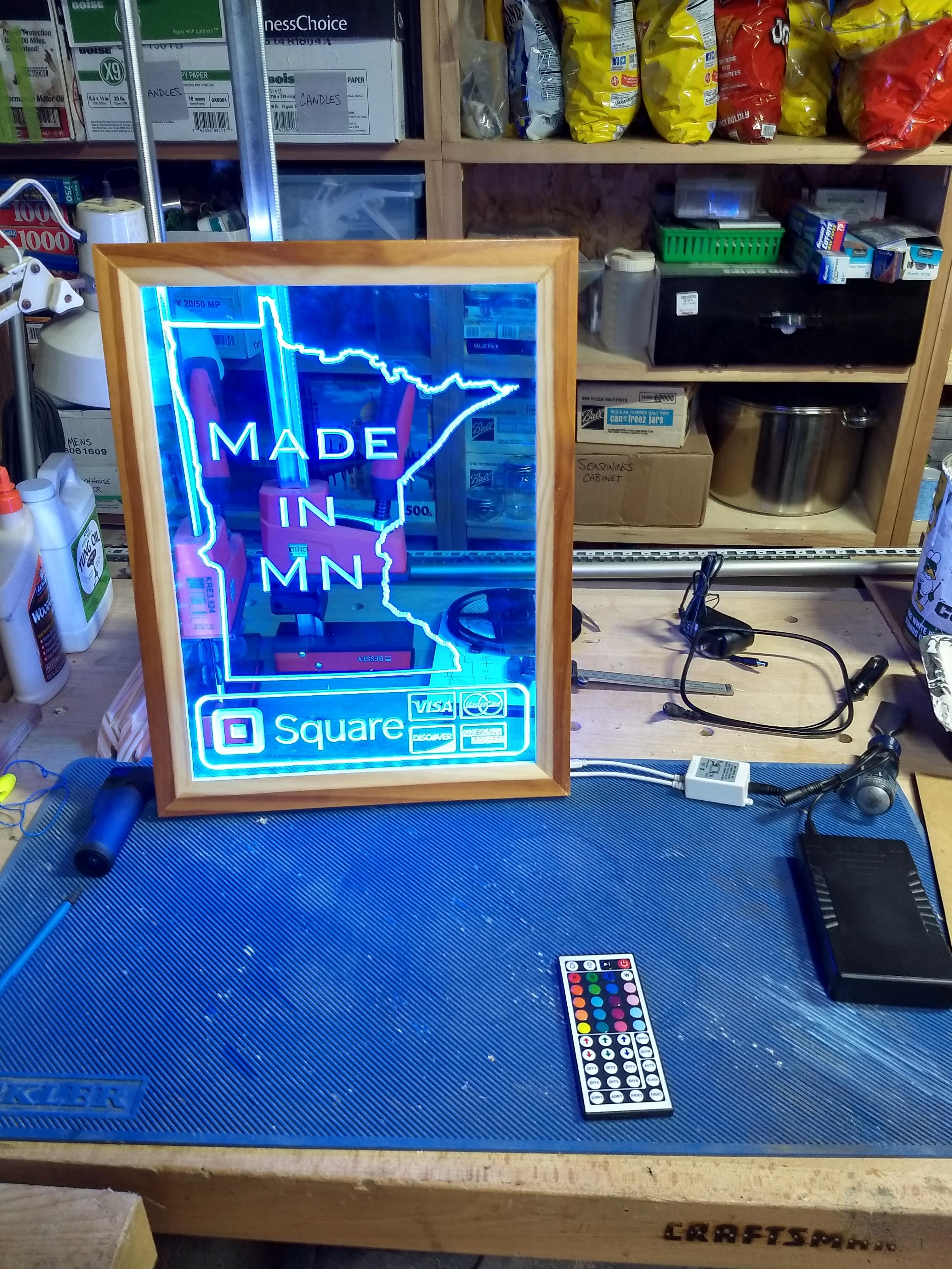
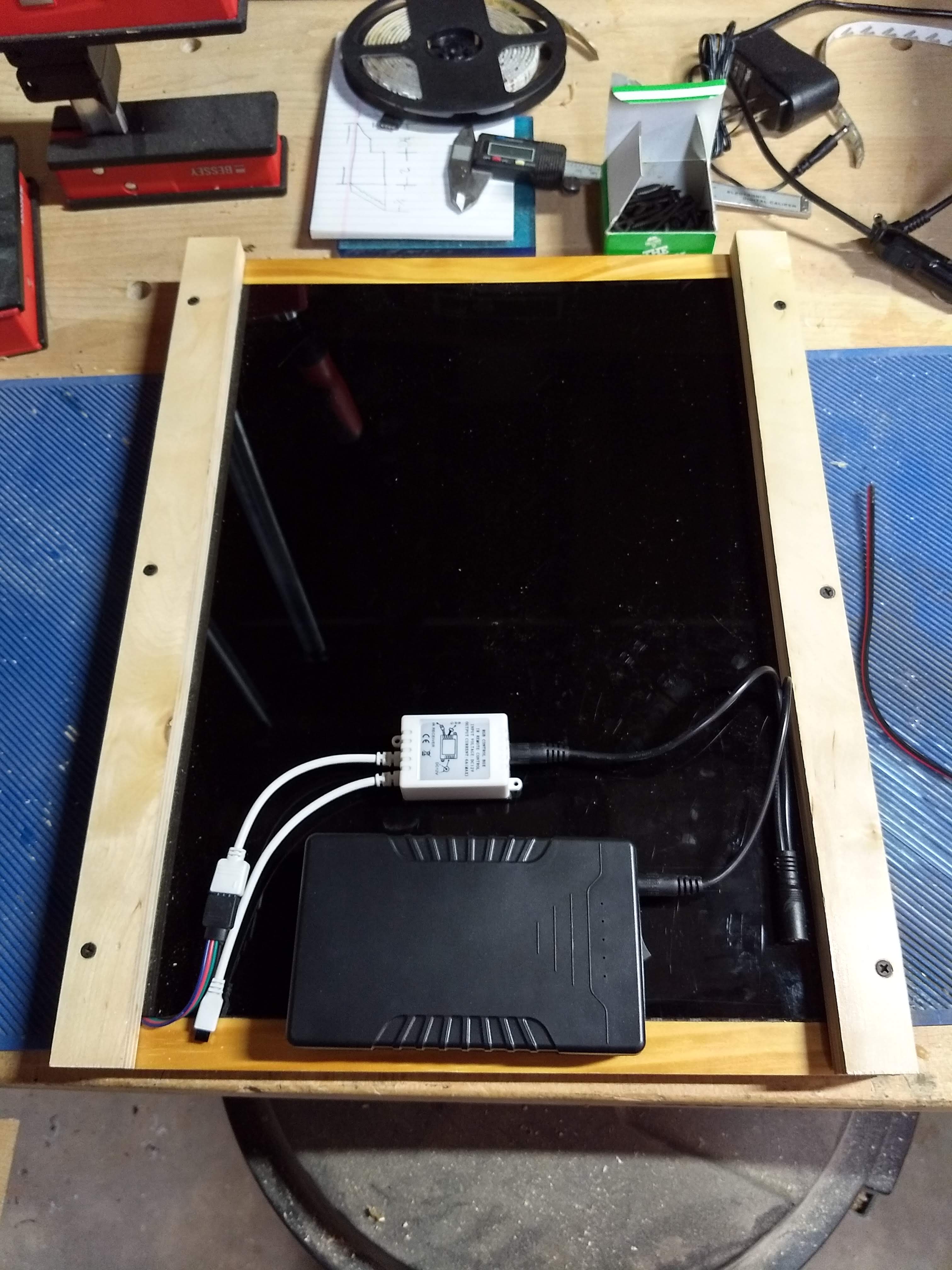
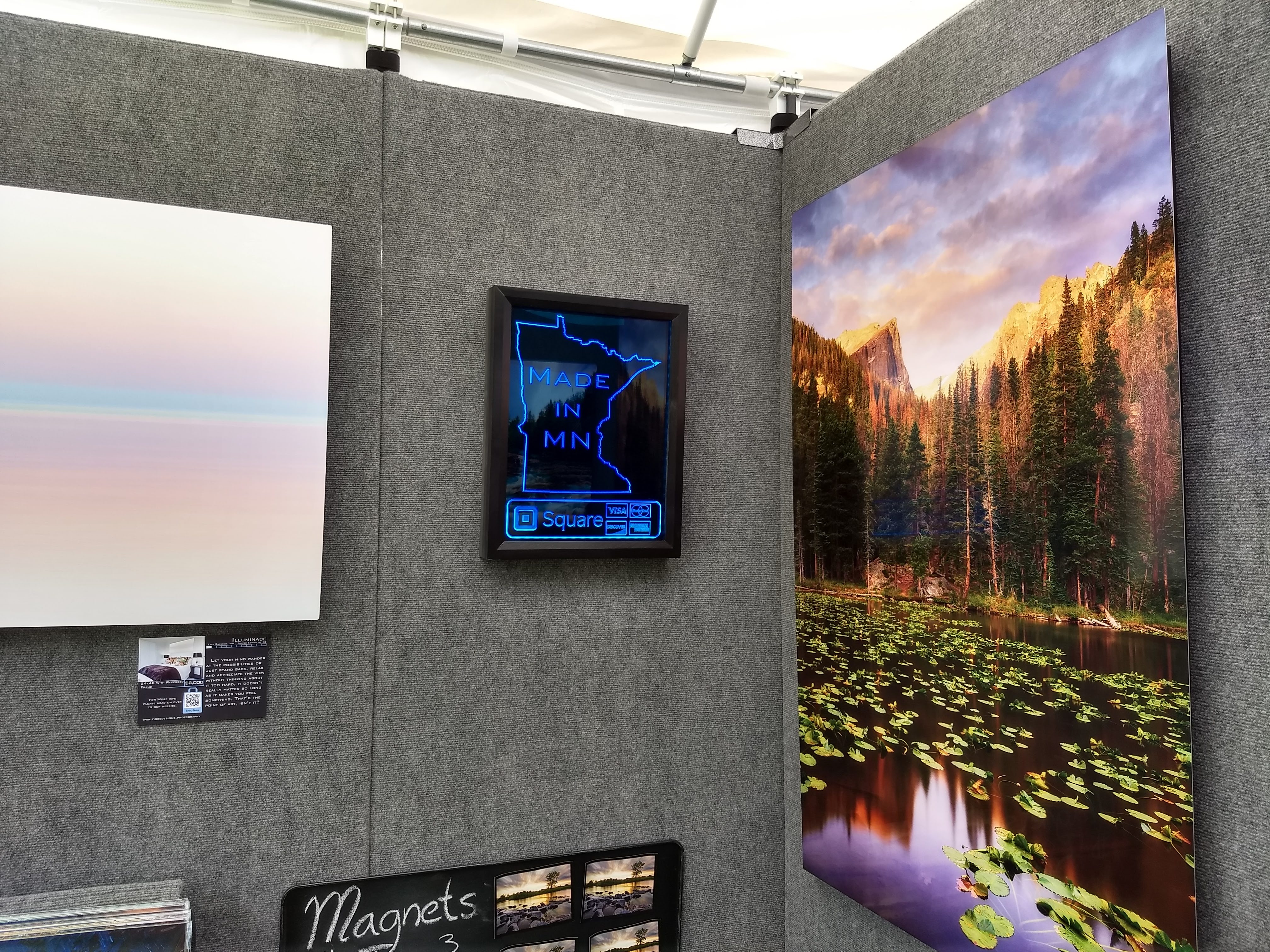
I was originally going to try to make an additional project and post that also but time has gotten away from me. I just had my first and only in-person art show of the year this past weekend due to COVID, hence why I felt the need to finally make this sign. Couple that with an early fall in MN I’ve been pretty busy and haven’t been able to make a real “Lamp” project.
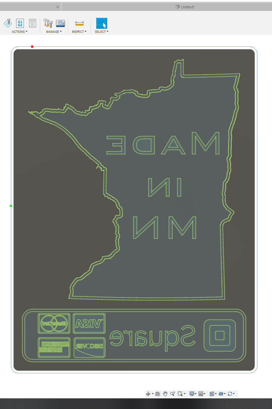
I’ve had the idea to make an edge lit sign that can hang on the walls of my tent/booth at art shows that clearly tells everyone that all prints/products are made in MN, and that I accept credit cards via Square.
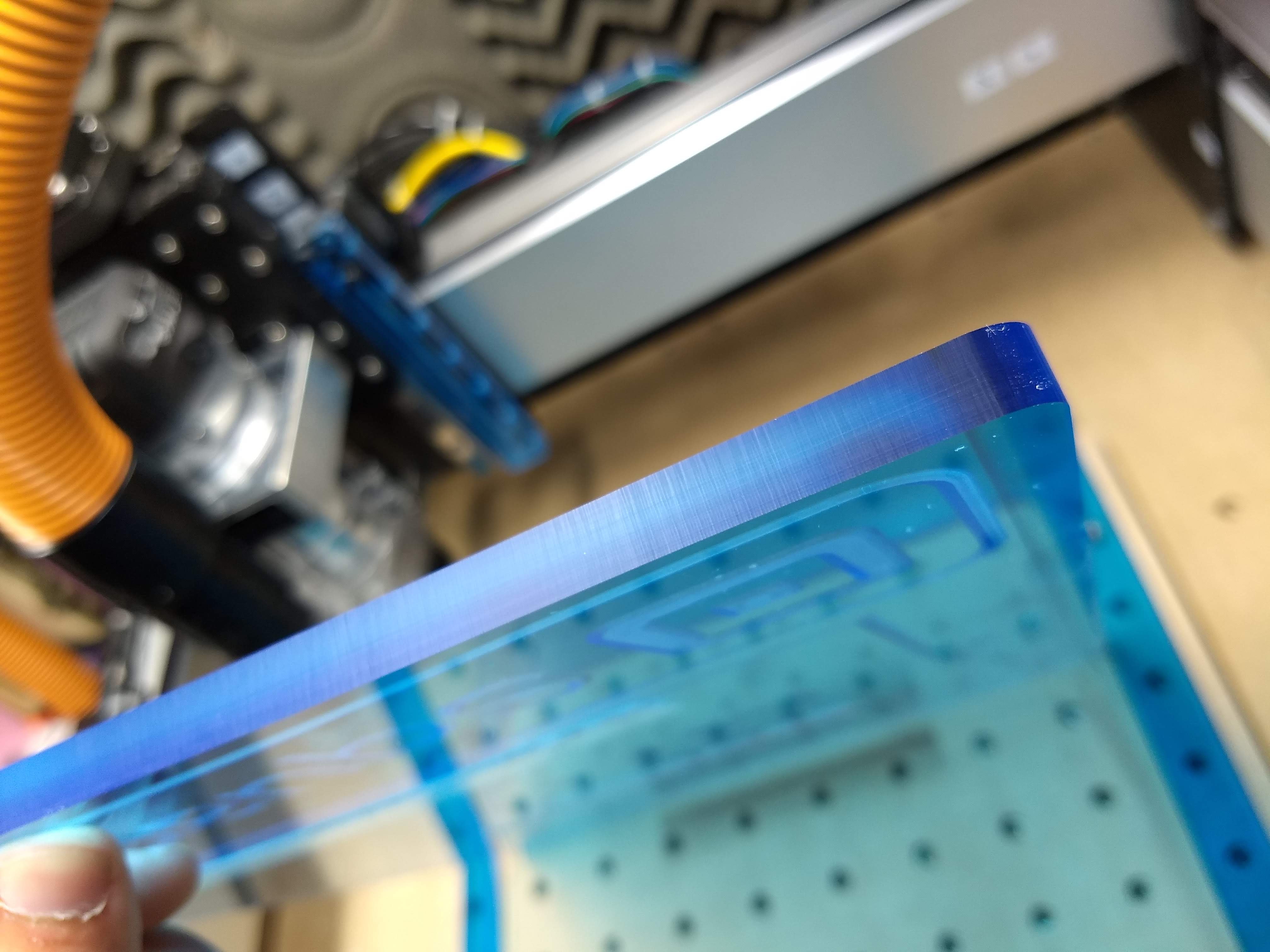
I first started off with a test piece to see if I had the right S/F for acrylic vcarving and a proof of concept.
EDIT: All the designs Elements in Carbide Create and indivudually in a zip folder
Made in MN Sign.c2d (743.5 KB)
Edgelitsignelements.zip (24.5 KB)
Awesome! How did the show go ?
Thanks, @Julien and the Carbide team for prompting me to take on this long standing idea!
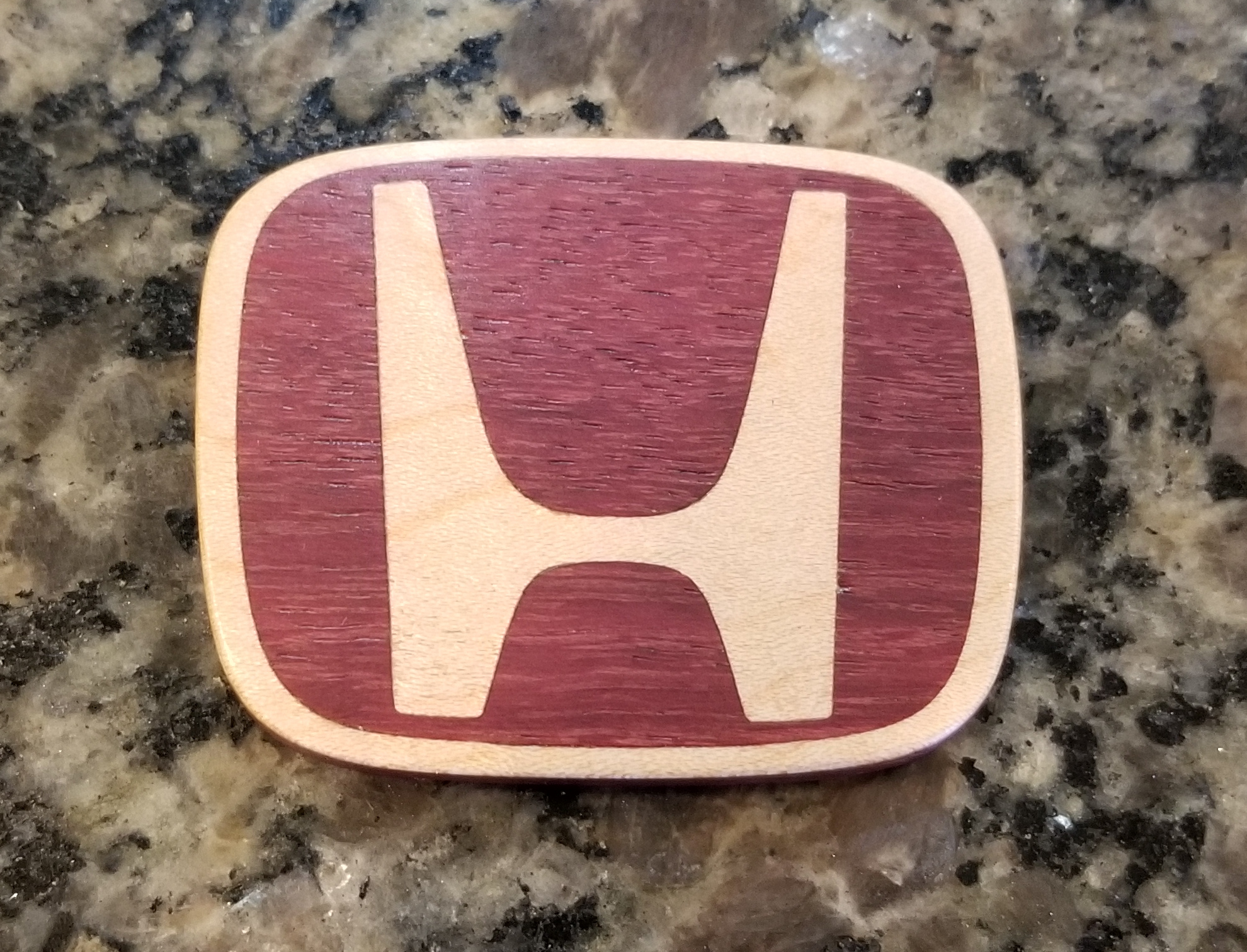
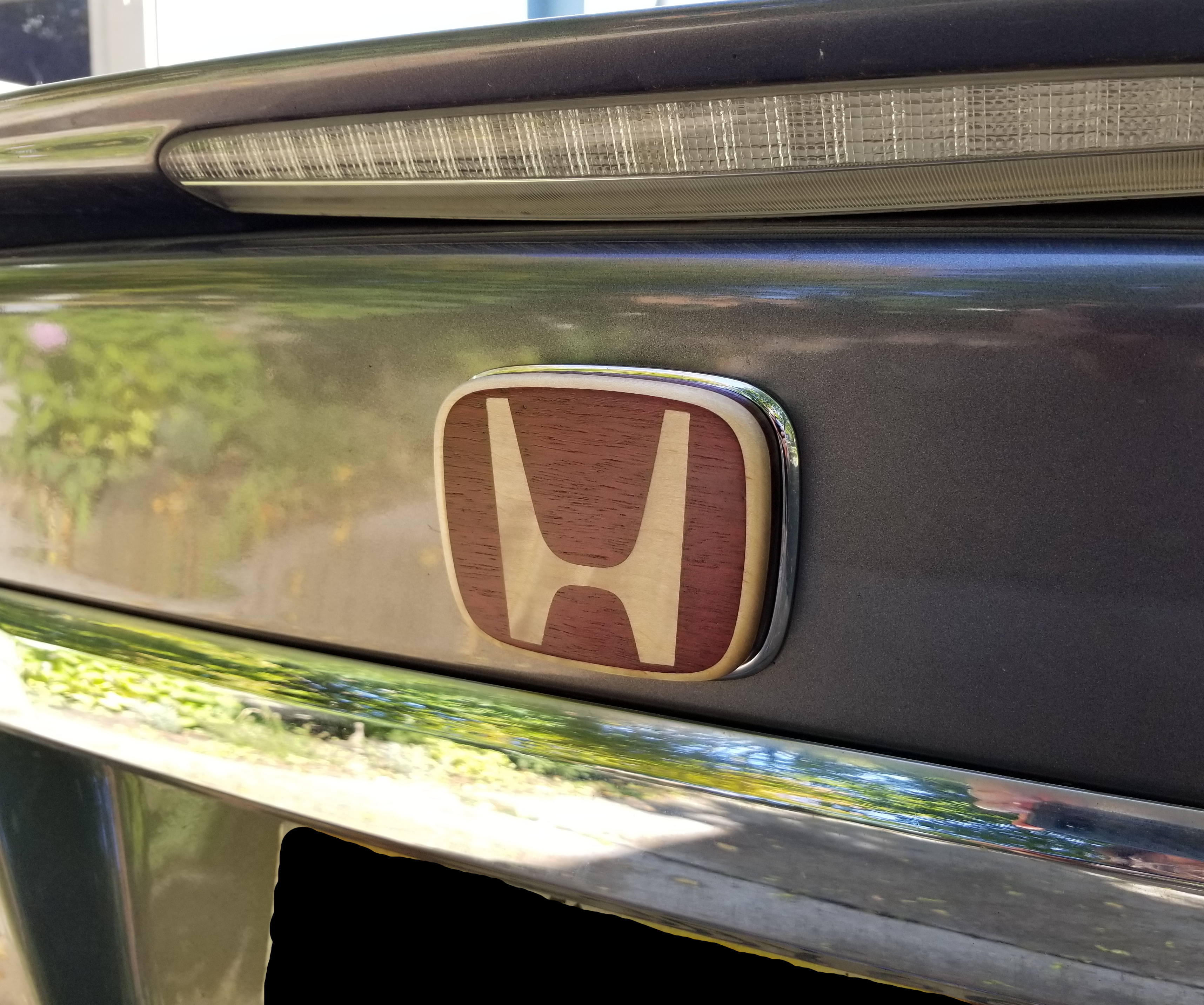
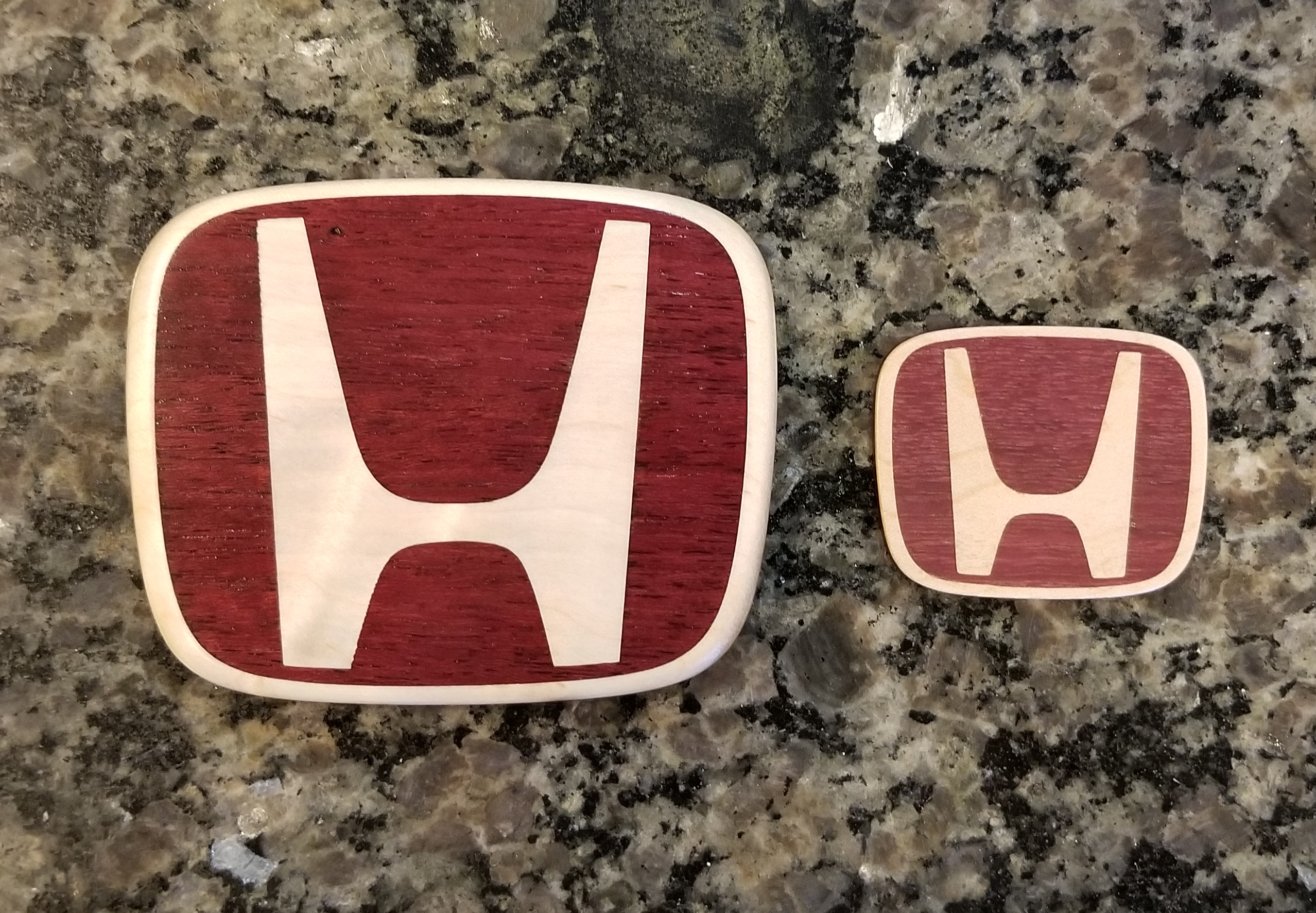
For quick background on the idea, when I first got my S3 about 1.5yrs ago, one of my early projects was a Honda badge for my steering wheel (this is ~2in wide x 1.6in tall):
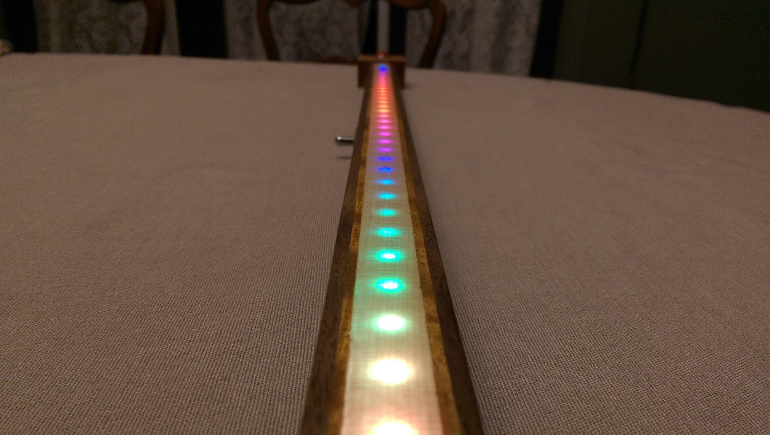
Long ago, I was inspired by this 1D pong creation and made my own for my nephew. Early in the build, I wondered “could you make wood thin enough that it looks like wood normally, but would let light through it?” Turns out, yes, yes you can:
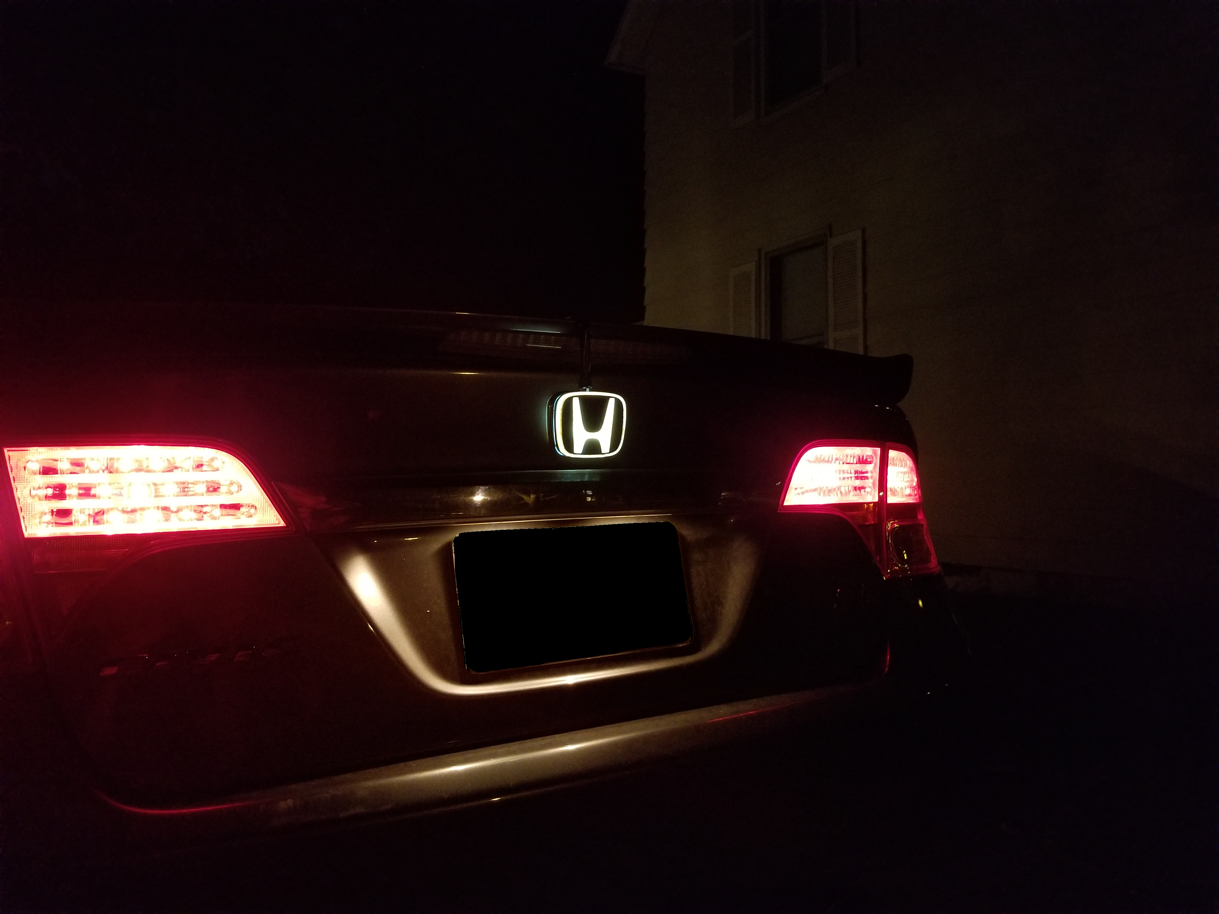
So, I present the brain child of these two concepts: a gorgeous, wood-by-day, eyecatcher-by-night Honda badge:
I was going to actually install this, but a) ran out of time as I’m leaving to go camping in ~1hr in northern MN and b) think I learned enough to make some tweaks for a final version. In these mockups, the badge is just taped to my current badge, but the nighttime demo really is hooked into my tail lights, which was my goal in using a 12V LED for the light source (it’s a dome light retrofit)!
Here’s proof, with my son locking/unlocking my car to show it off
I’ve never done one of these contests before and don’t know the appetite folks have for gory details, so I put the full log of annotated build pics on imgur for those interested.
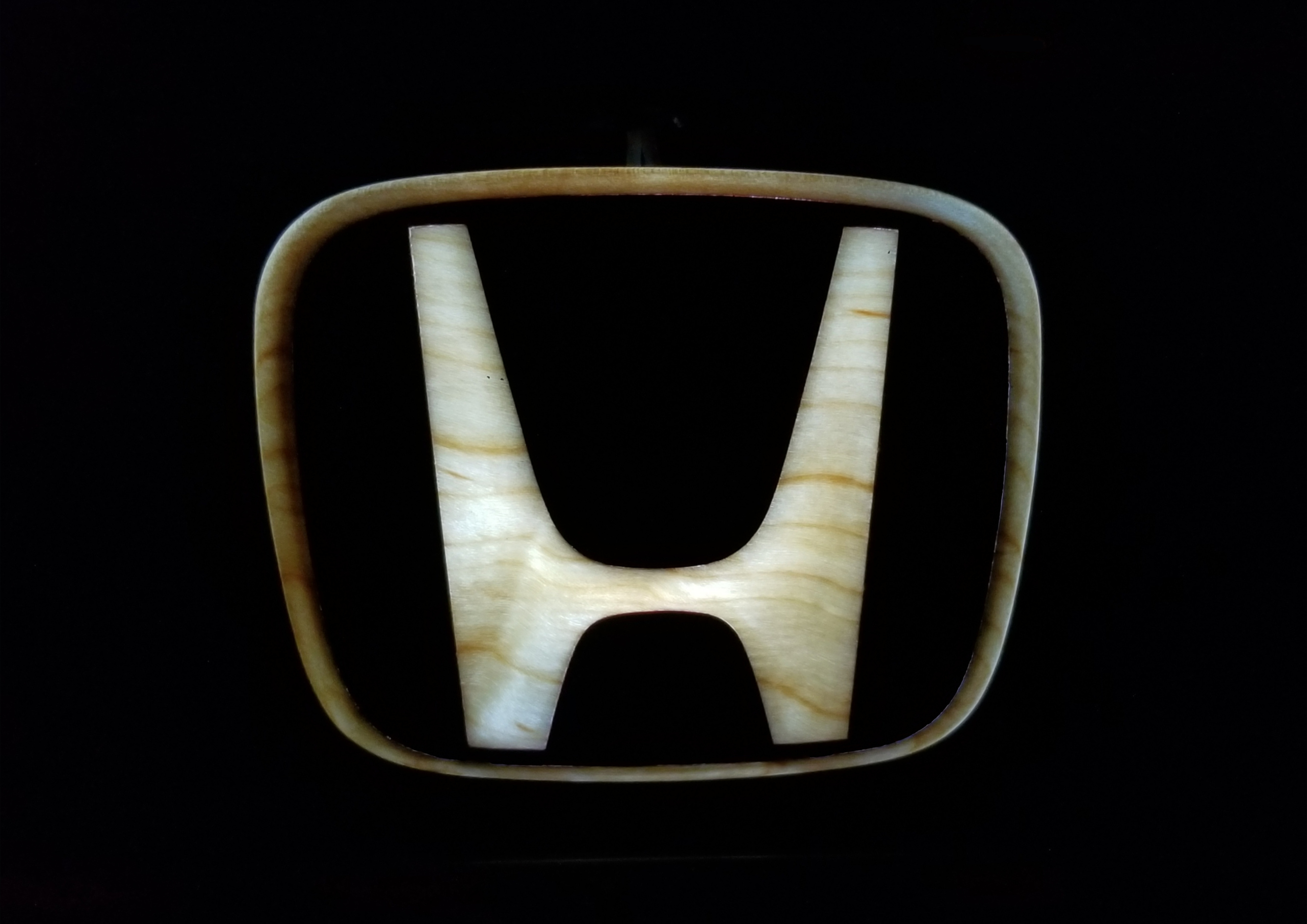
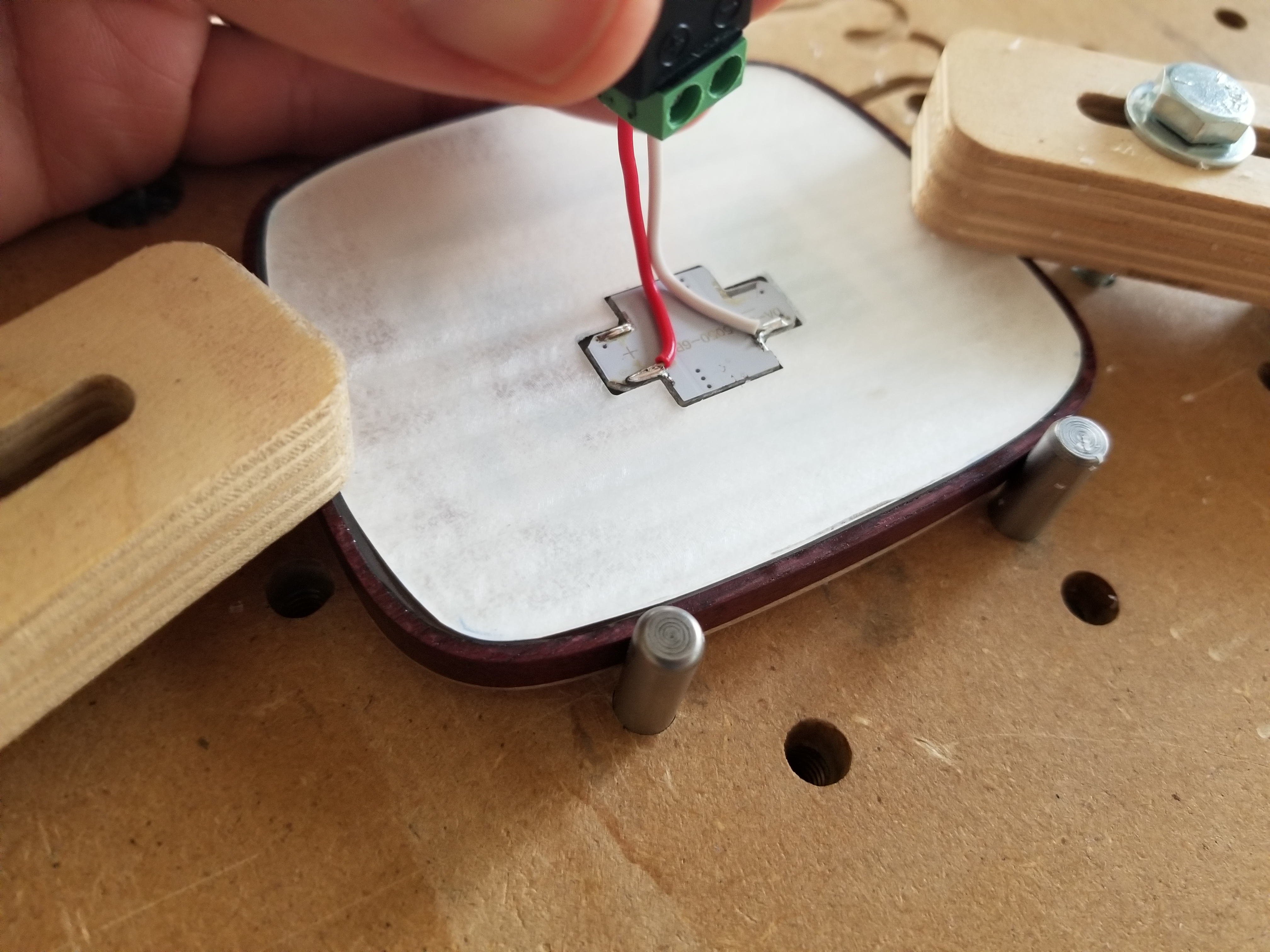
For the quick and dirty, the badge is a wooden shell, backfilled with epoxy. I used a small amount of white pearl powder to make the epoxy diffuse just behind the H and ring. Then I lined the entire thing with mirror film to give me the best shot of getting the light bouncing around from a point source to evenly illuminate everything.
I machined a backplate from acrylic for the back, which is also lined with mirror film, and then machined a pocket for my LED light (mirror film is down in this pic, you’re seeing the machined back of the acrylic).
I learned a lot, and am happy to answer questions on what I’d do differently. I consider this version as exceeding my expectations (really did not expect it to look so darn cool at night, and though my light would be too weak and get dwarfed by the tail lights). That said, I have enough tweaks in mind that this will live on as a nightlight in my son’s room.
I hope to outfit the front/back with these one day, and I love that it matches my steering wheel emblem so nicely!
For a quick summary of some thoughts/lessons learned:
Here’s the project on cutrocket and another link to the full build pics in case it was missed above.
Disclaimer: I generally don’t know what I’m doing in CAM world, so I end up with pretty Frankenstein-ish models, setups and operations. If it’s in there, I probably used it at some point.
Final disclaimer: the legality of this is not clear to me. To the original post’s comment about sharing vectors… the no-nos appear to be representing something that’s not a Honda as a Honda by labeling/badging and/or selling it as though it’s made by Honda. I’m doing neither, and there’s plenty of precedent for aftermarket badges that I doubt are from Honda (like this and this). To play it safe: limit to your own car and don’t sell these.
The show was awesome, plenty of space for everyone to keep there distance if they wanted and whatnot. Saturday sales were slow, but Sunday made up for that. Everyone, artists/organizers/customers, I talked to seemed really happy the event happened.
CHILD’S NIGHTLIGHT
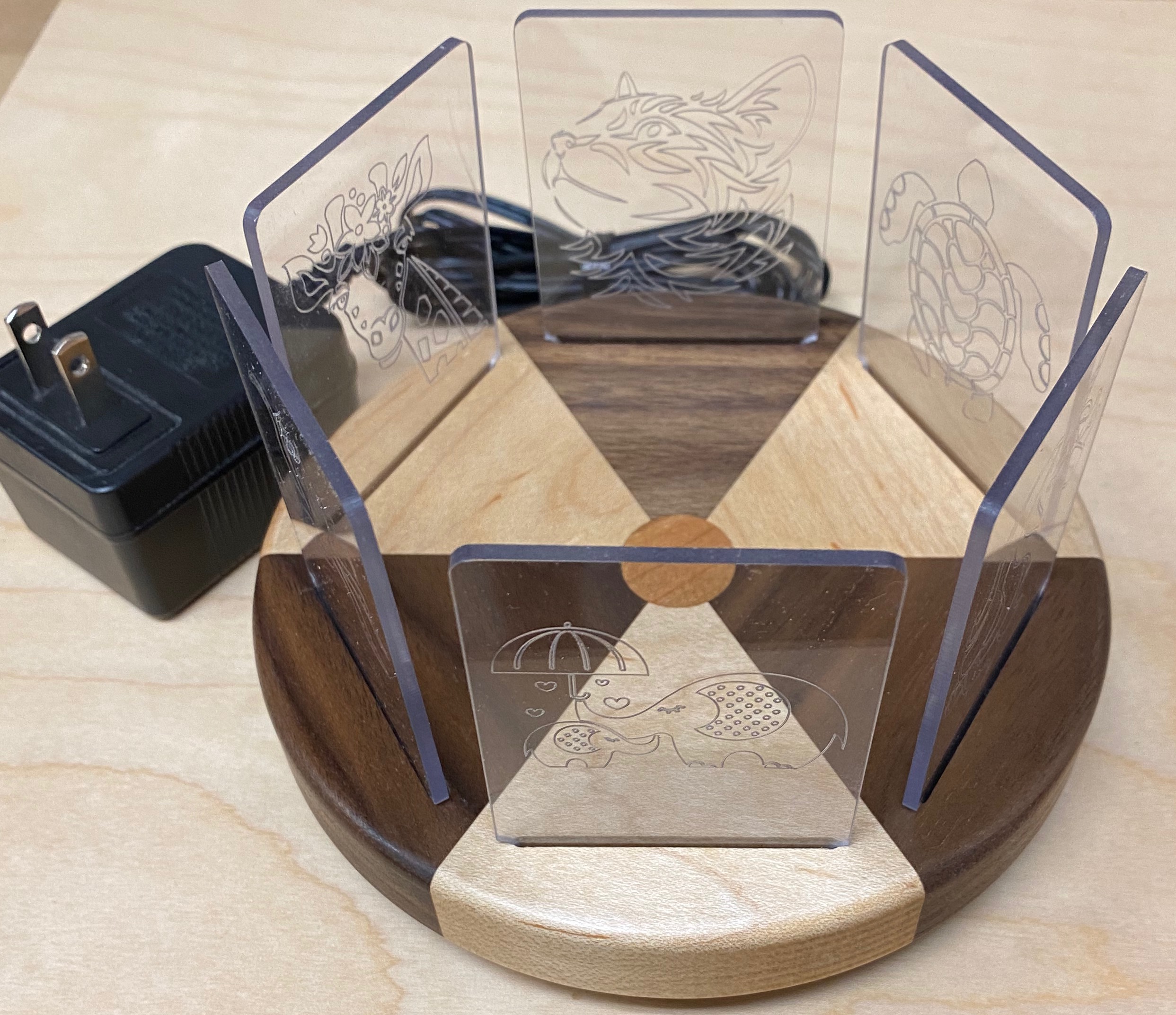
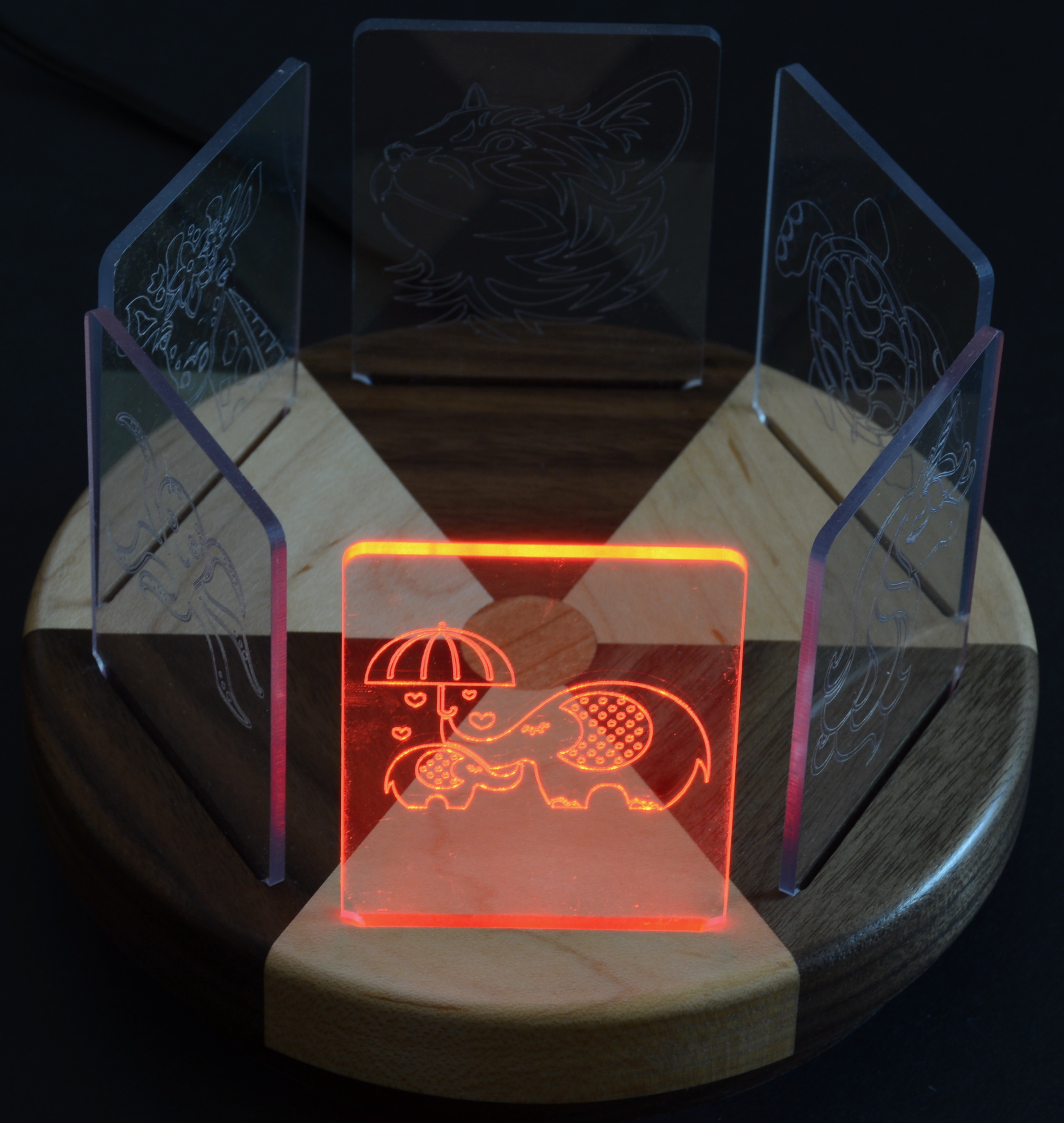
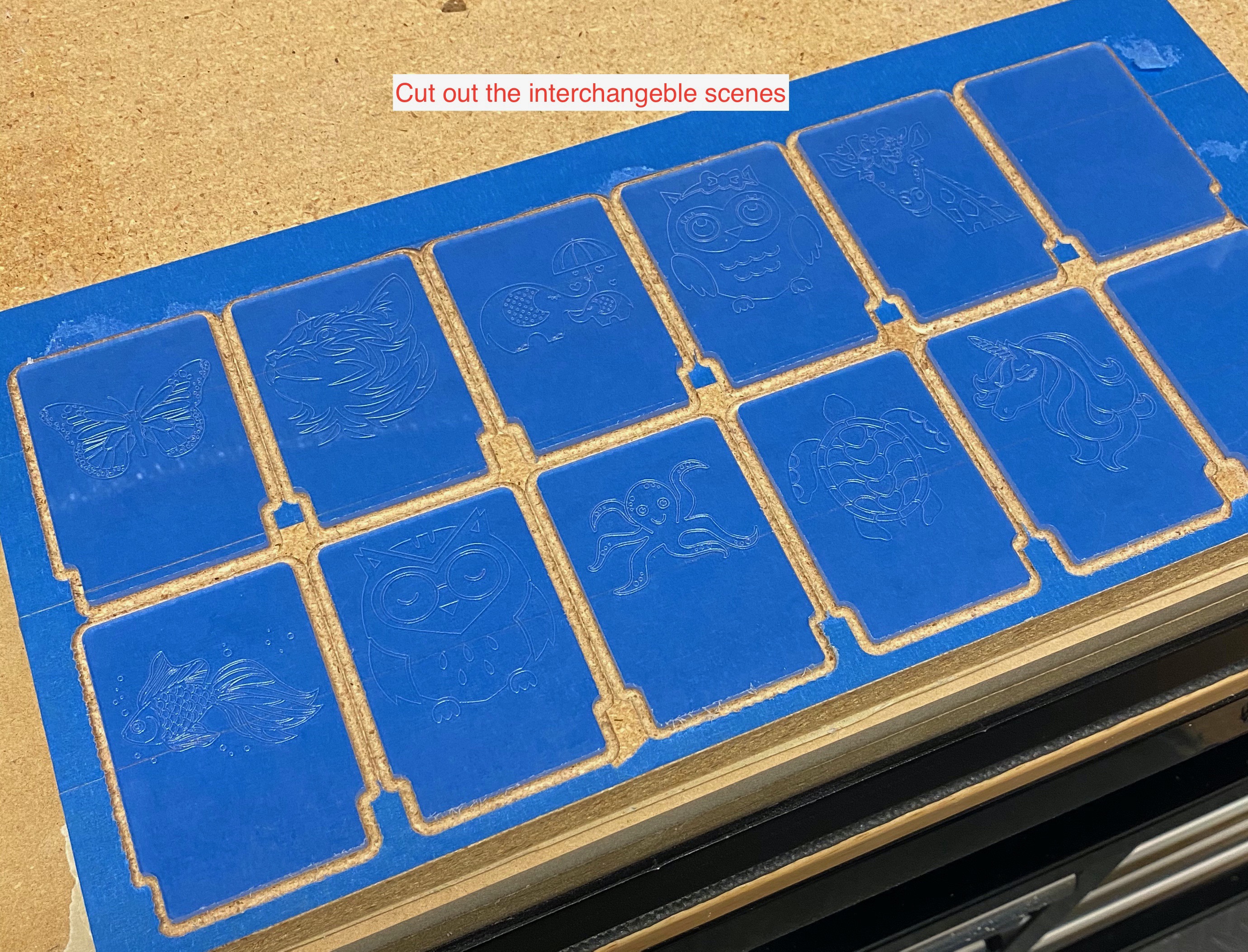
Here is my edge-lit Child’s Nightlight with interchangeable scenes so it can be refreshed as the child grows.
Here’s a YouTube video of how it works:
DESCRIPTION
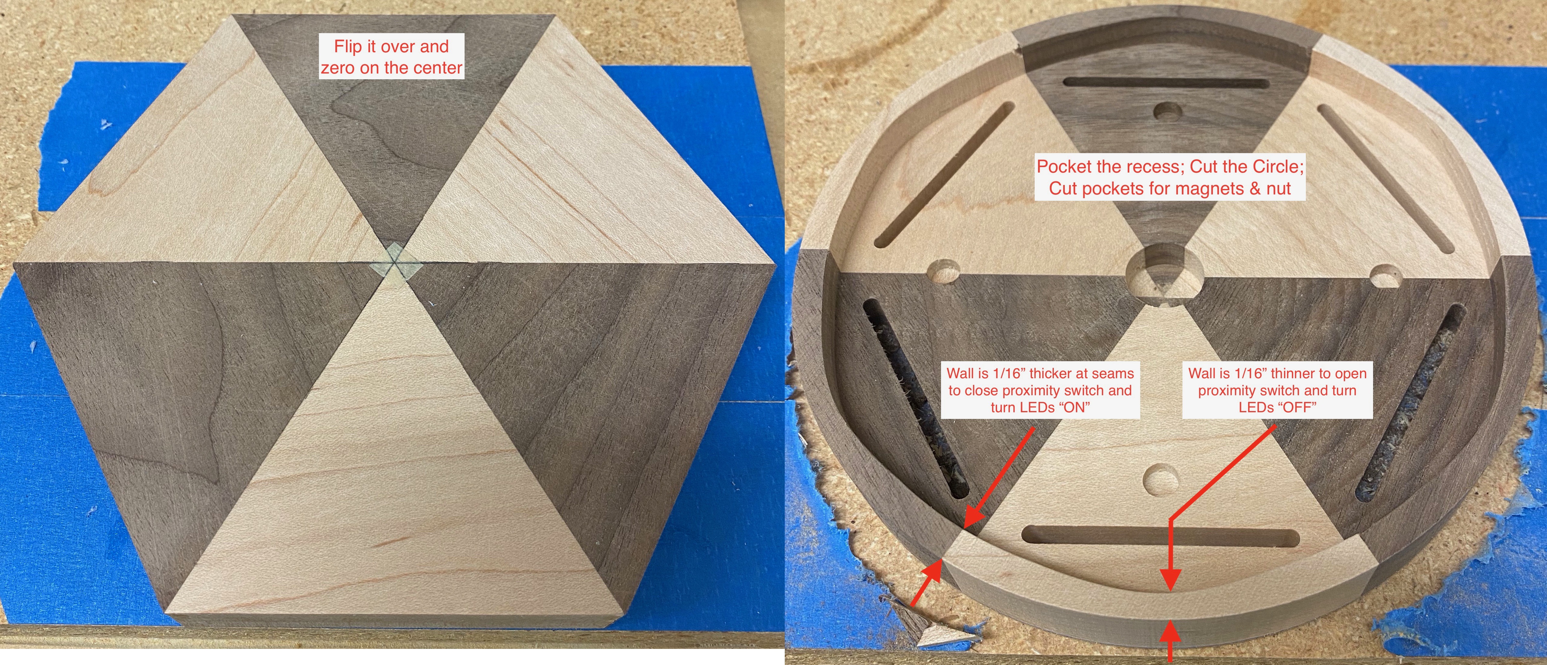
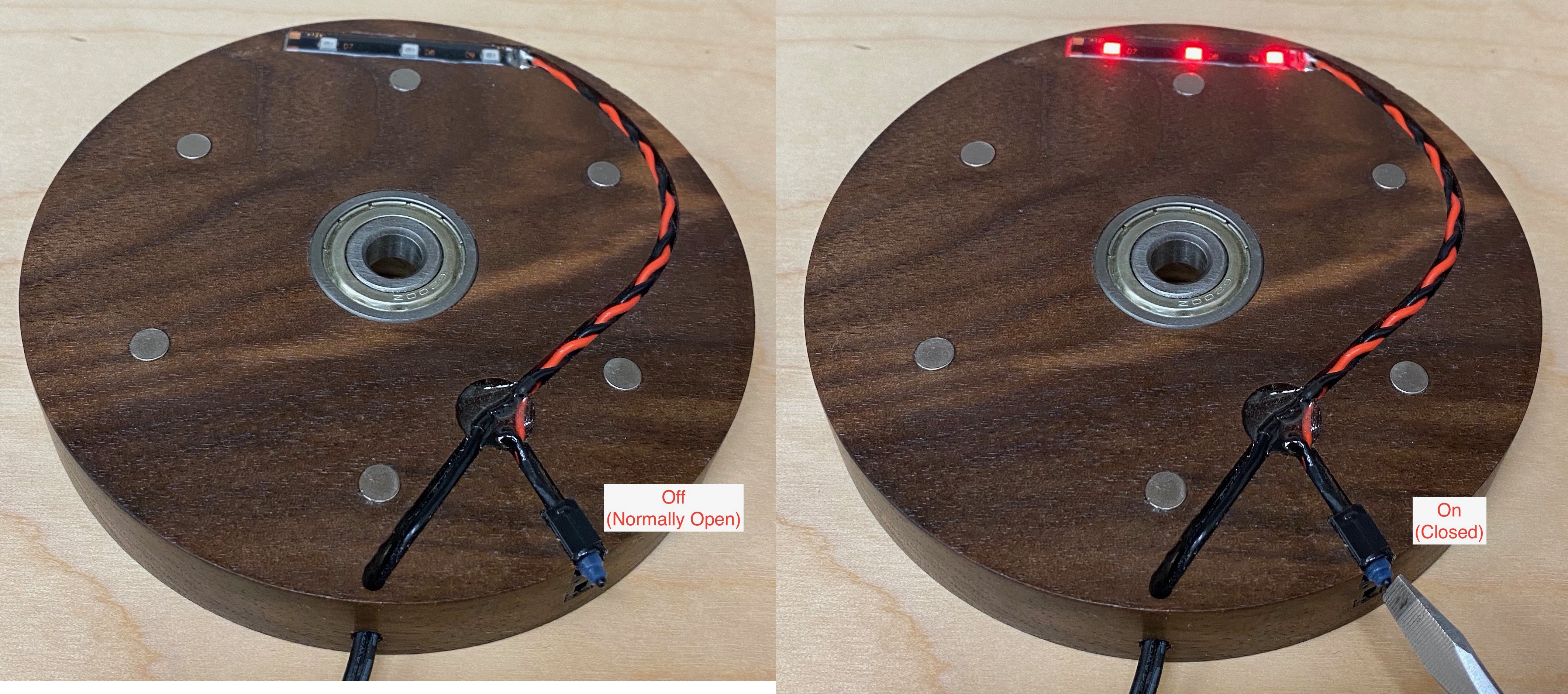
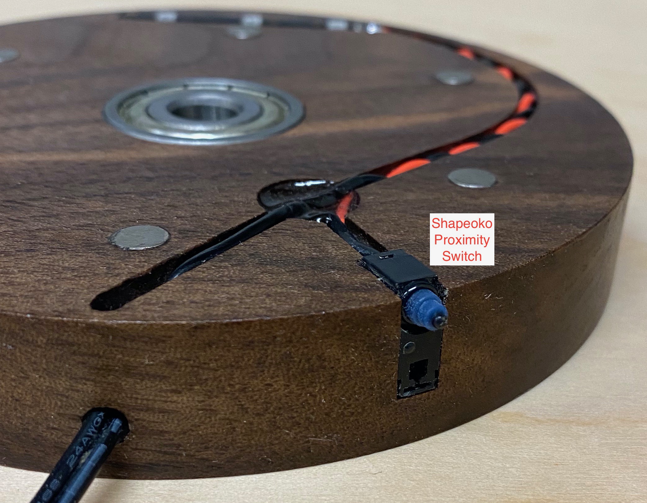
The 2”x3” Lexan “scenes” drop into slots in the top. Underneath, on top of the bottom disc, is a single 2” LED light strip that illuminates the “front” scene. It turns on/off by simply rotating the top (“On” when rotated to a scene; “Off” when rotated between scenes.). Rare earth magnets provide tactile “stops” all the way around so the top stops exactly on a scene (“On”) or between a scene (“Off”). On/off is controlled by a repurposed Shapeoko mechanical proximity switch that contacts a scalloped lip under the top piece.
I wanted to do Disney characters but didn’t want to run afoul of copyrights, so I found some fun “free for personal use” SVG files instead. This is more of a girl’s version (I’m biased since I have twin daughters), but I can envision dinosaurs, happy monsters or superheros for boys.
I made 10 Lexan scenes (because I couldn’t decide!), though the Nightlight only holds 6 at a time (dealer’s choice!)
INGREDIENTS (all stuff I had laying around):
LINKS AND FILES:
Cutrocket: https://cutrocket.com/p/5f6d145634749/
Nightlight Wood Parts.c2d (997.3 KB)
Nightlight Acrylic Cutouts.c2d (529.7 KB)
10 c2d scenes.zip (483.8 KB)
CONSTRUCTION PHOTOS:
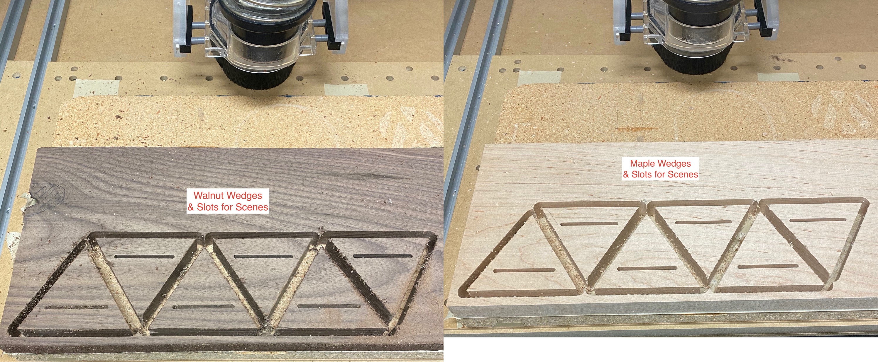
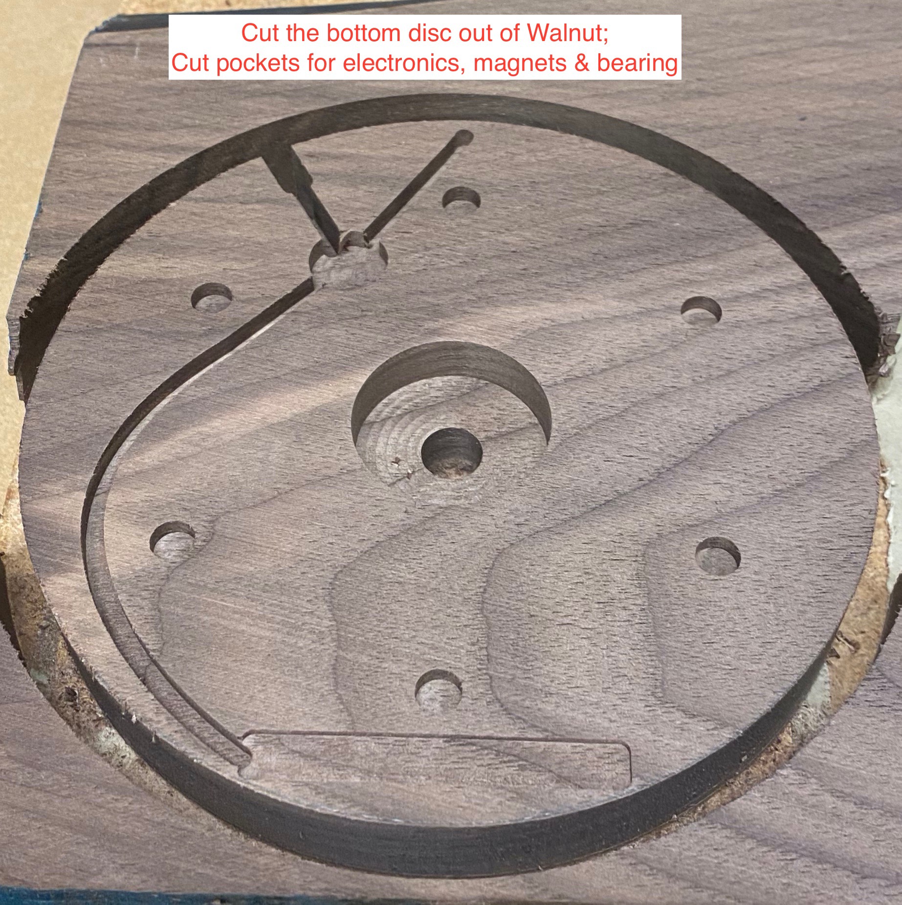
Cut wedges out of contrasting woods (I chose Walnut and Maple)…
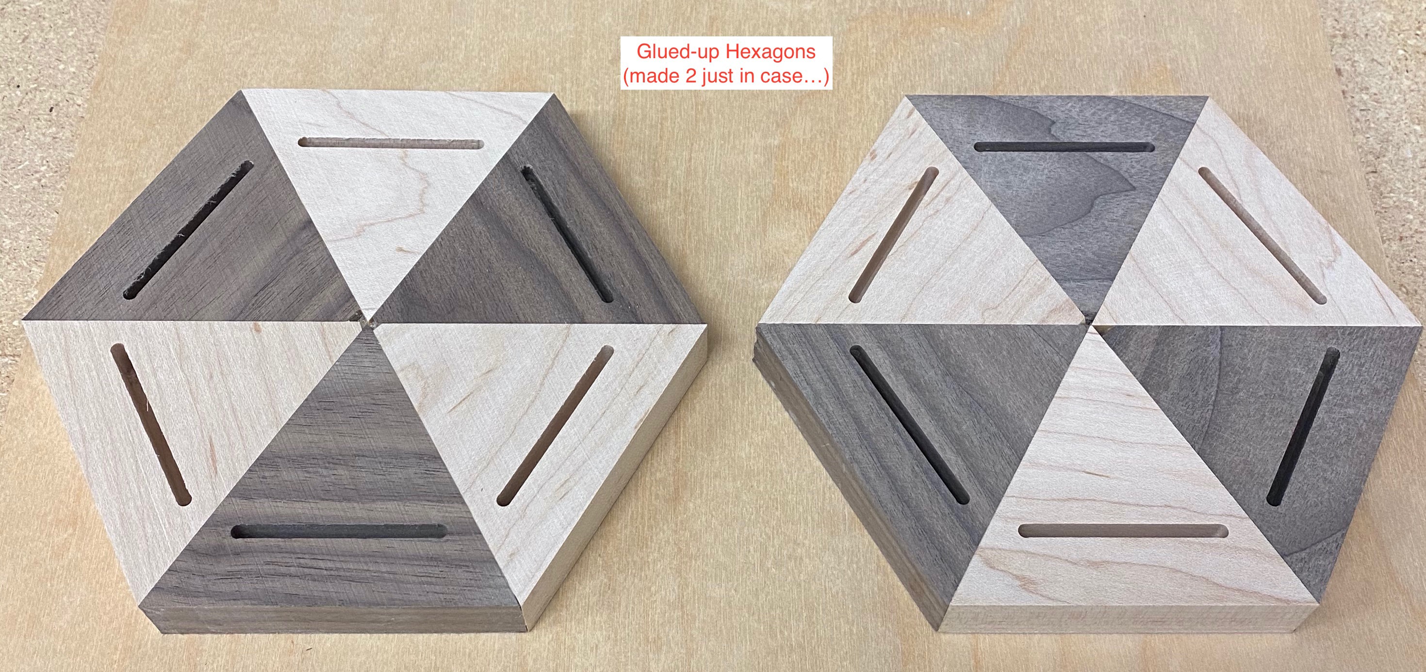
Don’t Worry about the chewed-up tips at the center - we’ll fix that with a decortive plug in a bit…
Machine the bottom side of the top half…
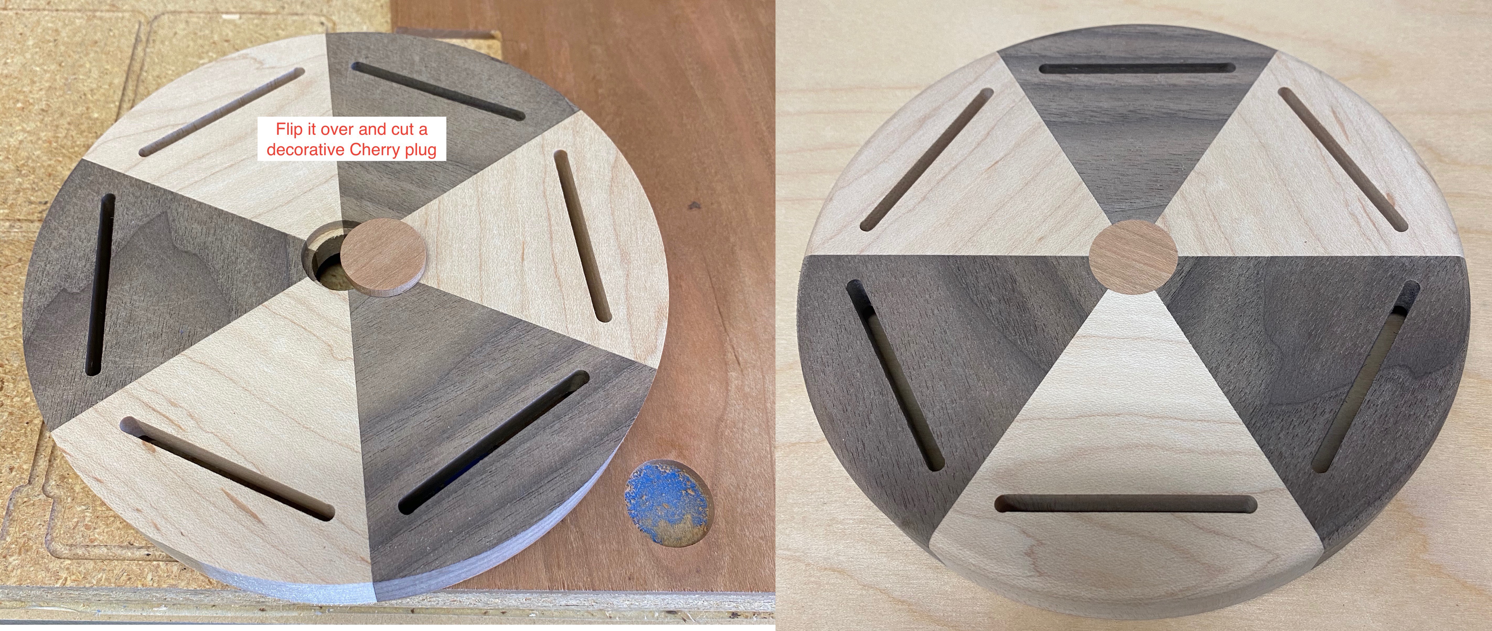
Now for that decorative plug on the top, made out of cherry…
Machine the top side of the bottom half…
Here are the guts with all the parts installed…
Testing the proximity switch…
A bottom view showing how the scalloped lip activates the proximity switch…
Now for the Lexan parts…
Closeups of each illuminated scene…
And the final result…
MISTAKES, TIPS, TRICKS, ETC
This was a fun project involving wood, plastic, electrical elements, mechanical elements, photography and some head-scratching design work. And 100% “free” with stuff I had laying around. Oh, and made on my Shapeoko XL that I’ve had for about 11 months. Thanks for inspiring me to participate.!
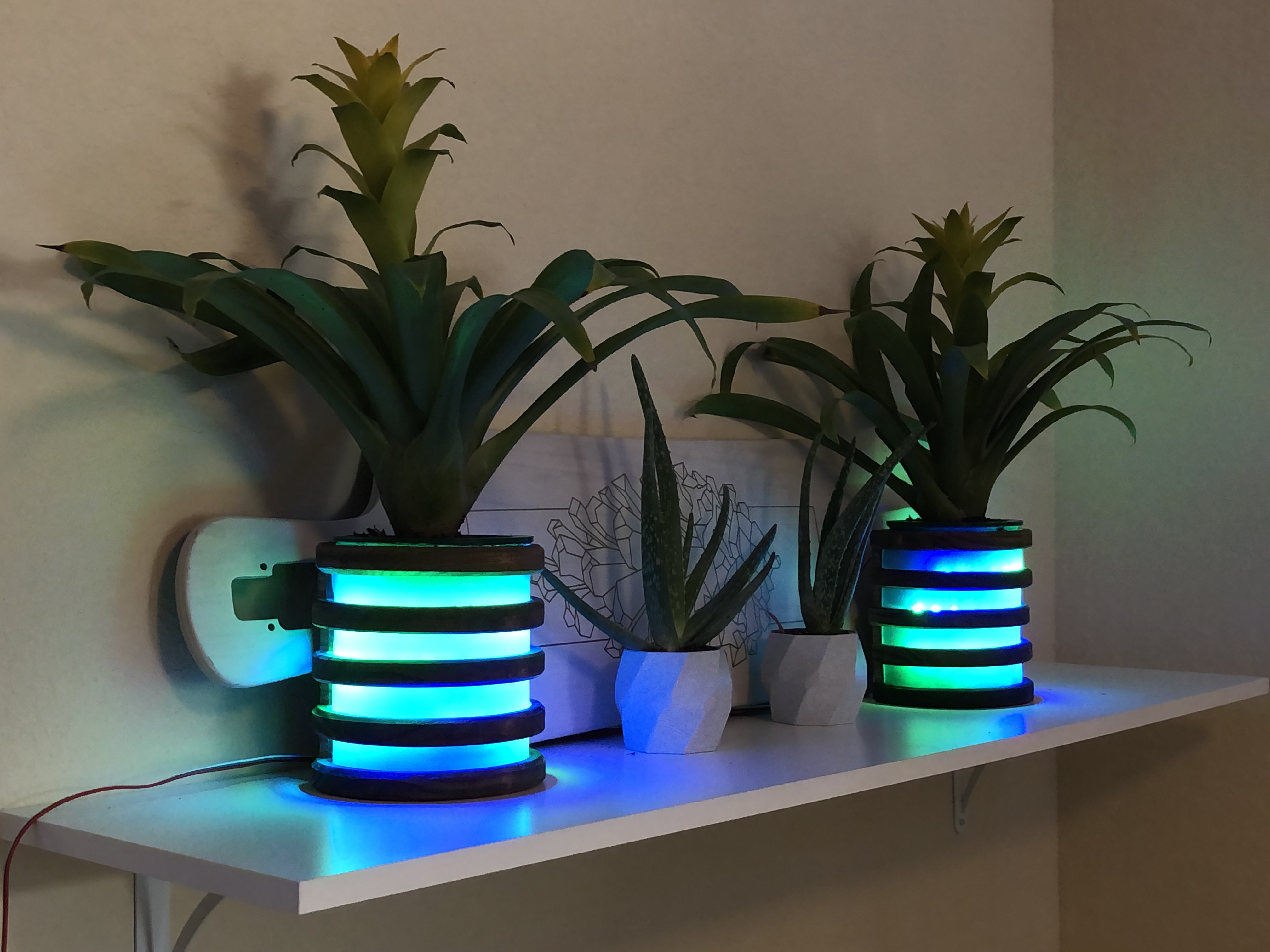
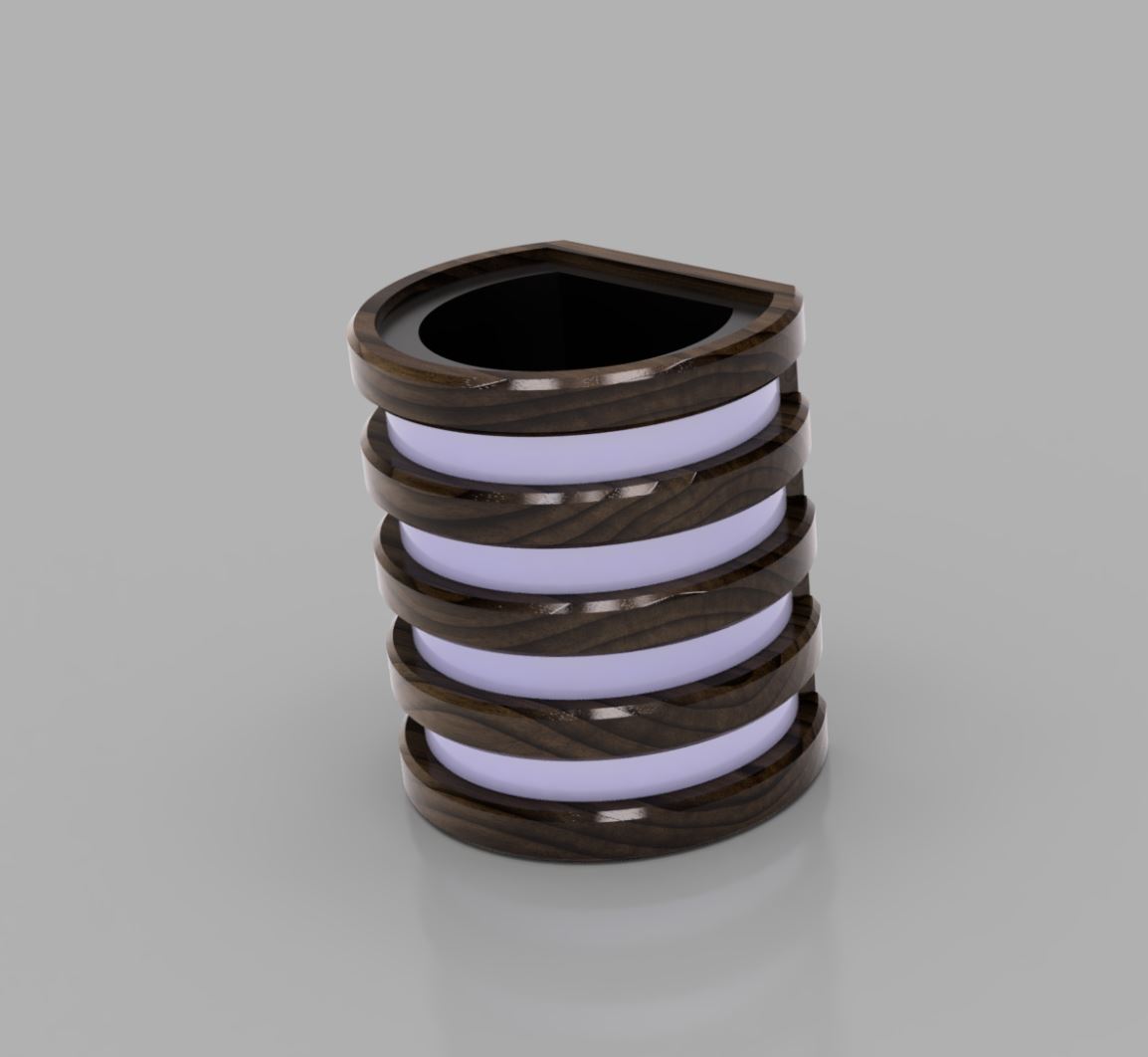
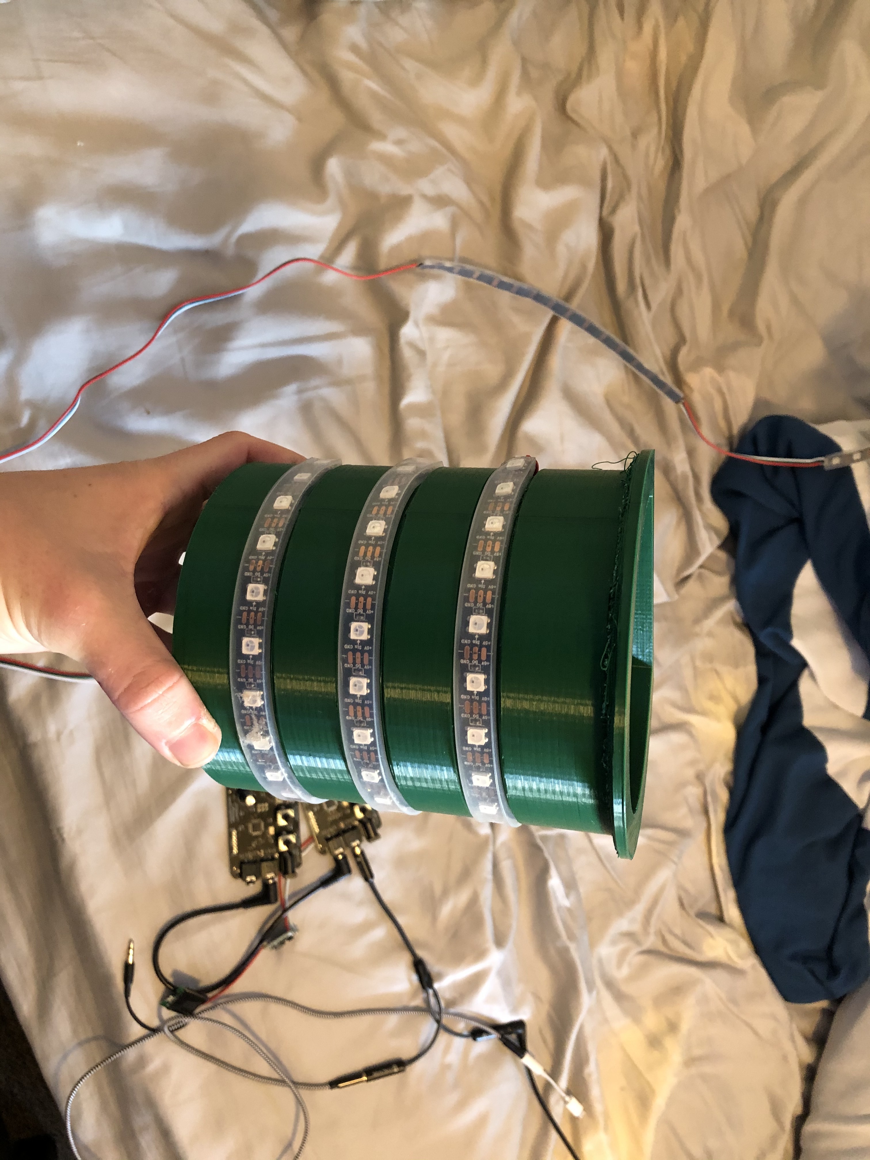
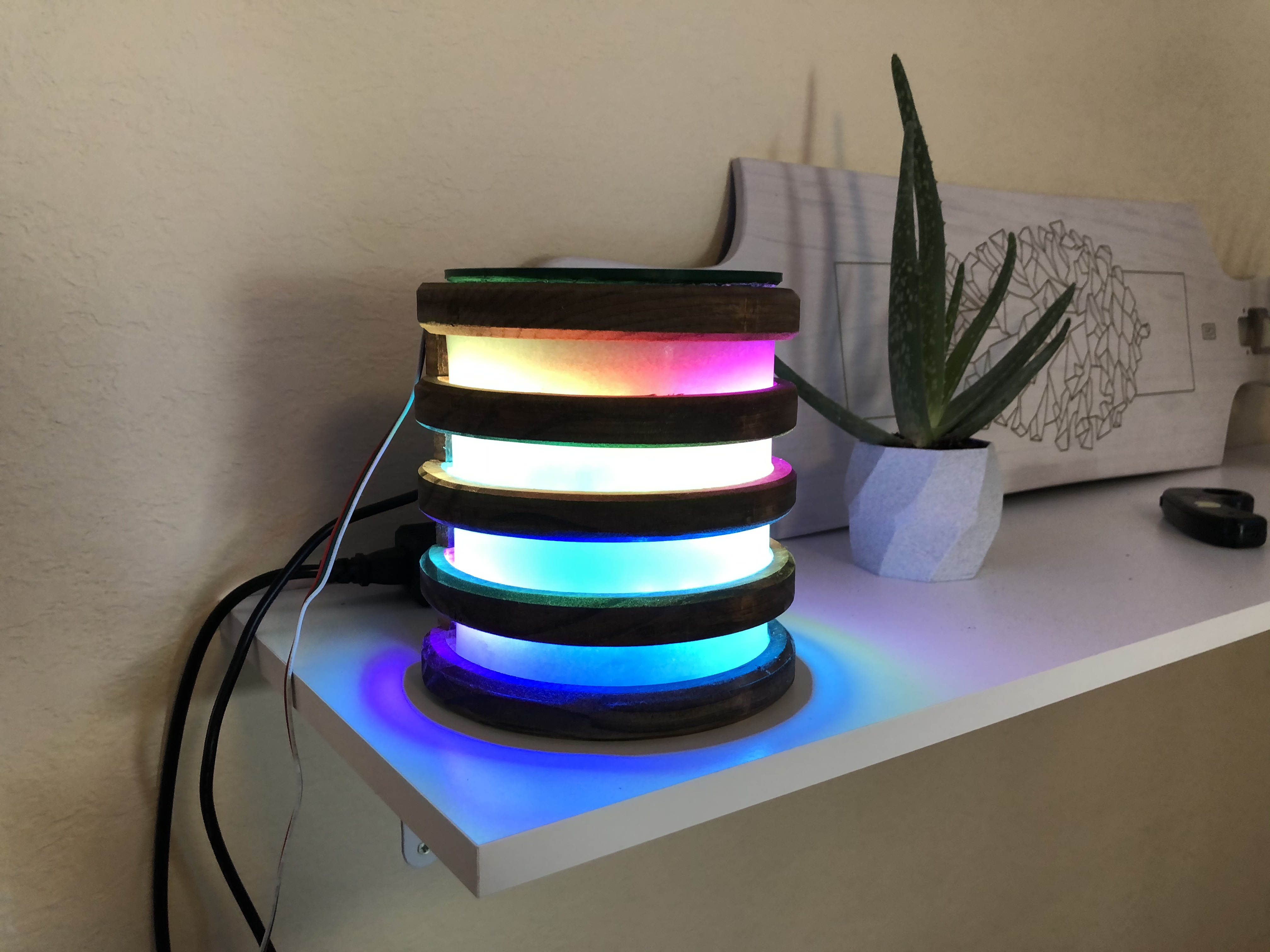
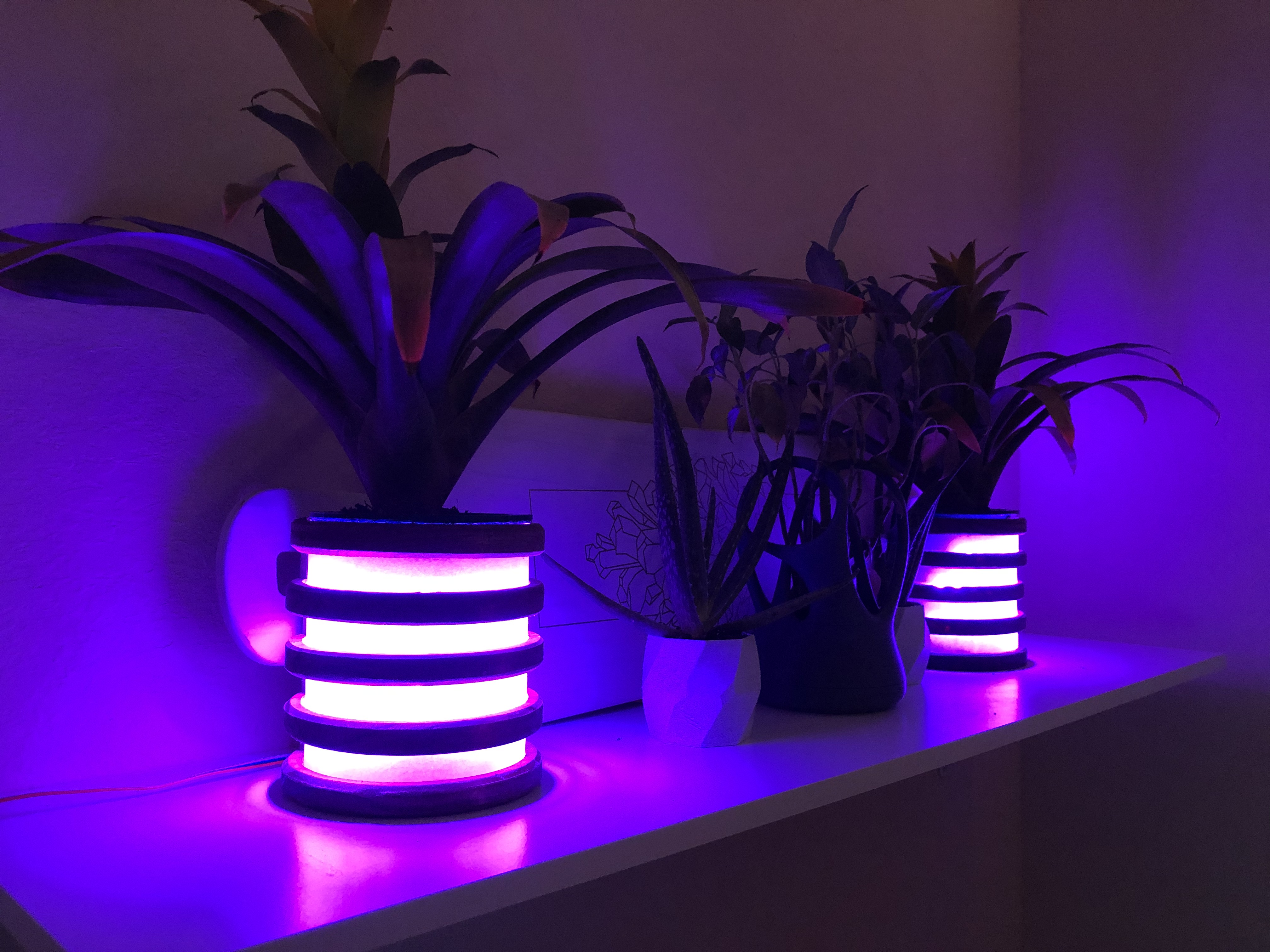
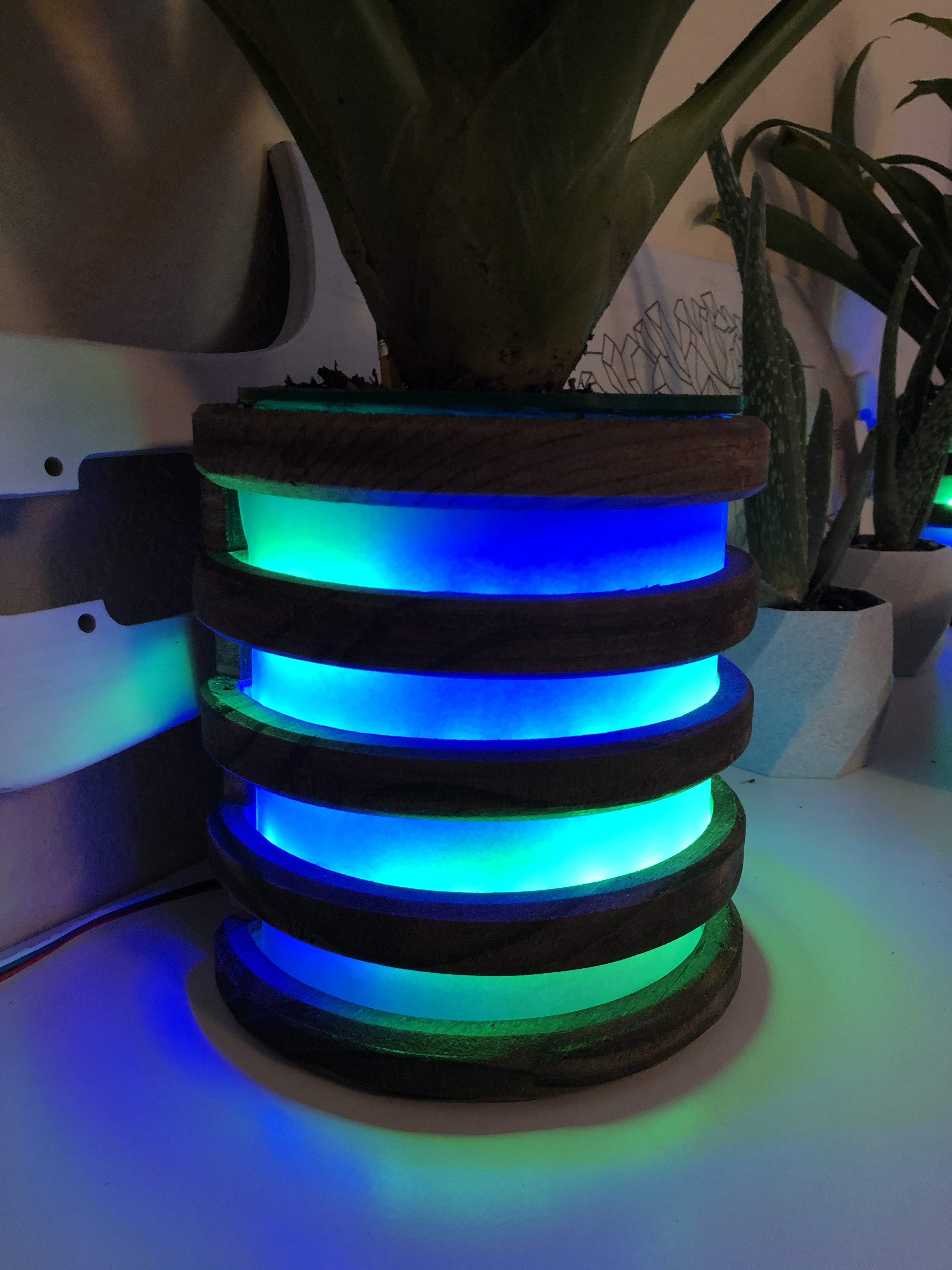
Plant? Lamp? Nah, its a Plamp. (aka LED planter)
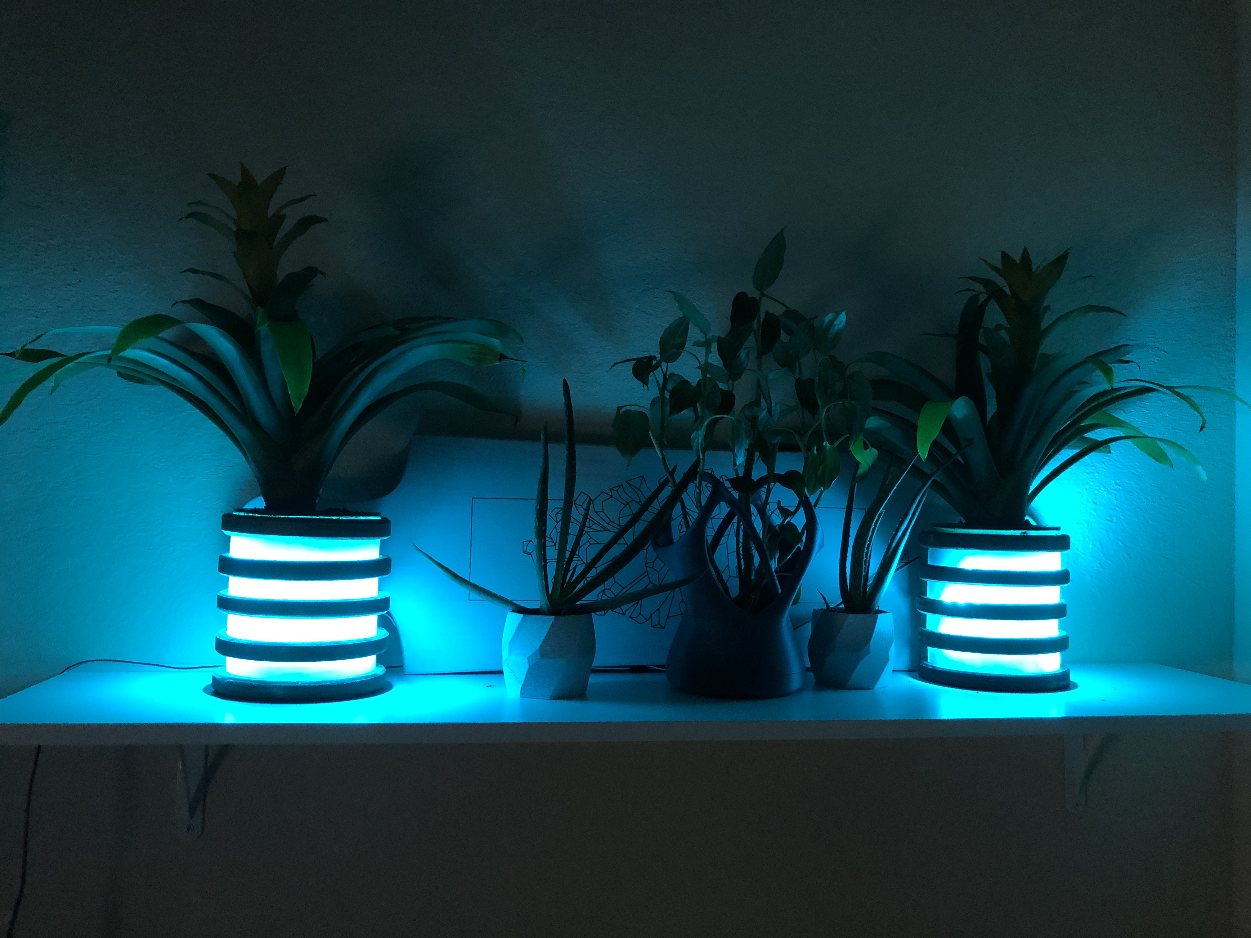
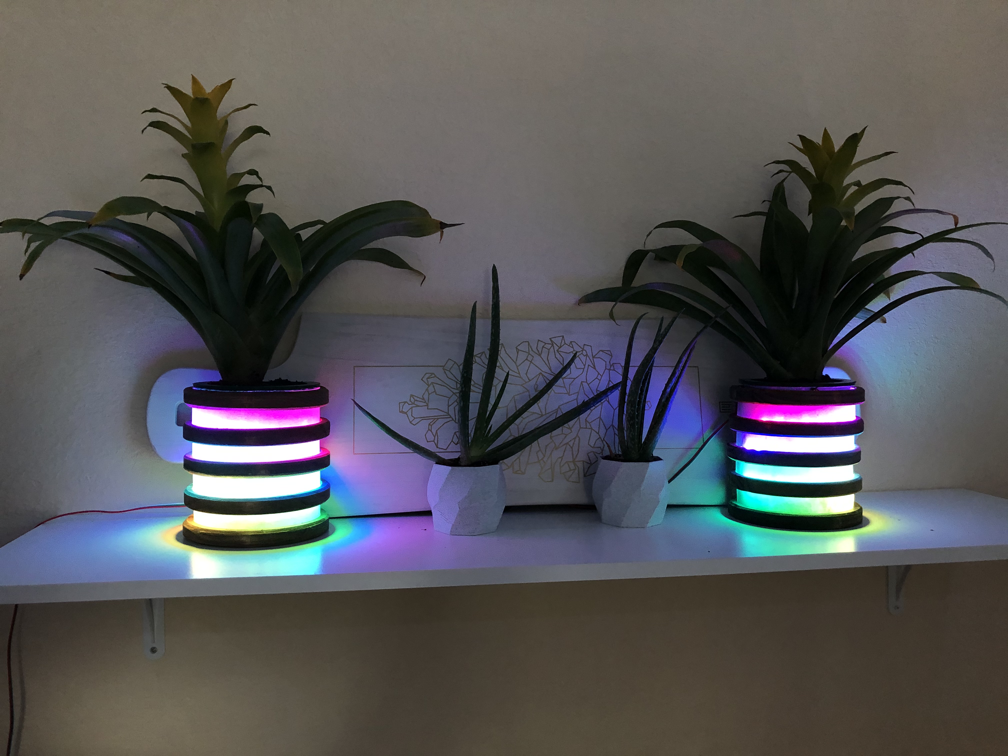
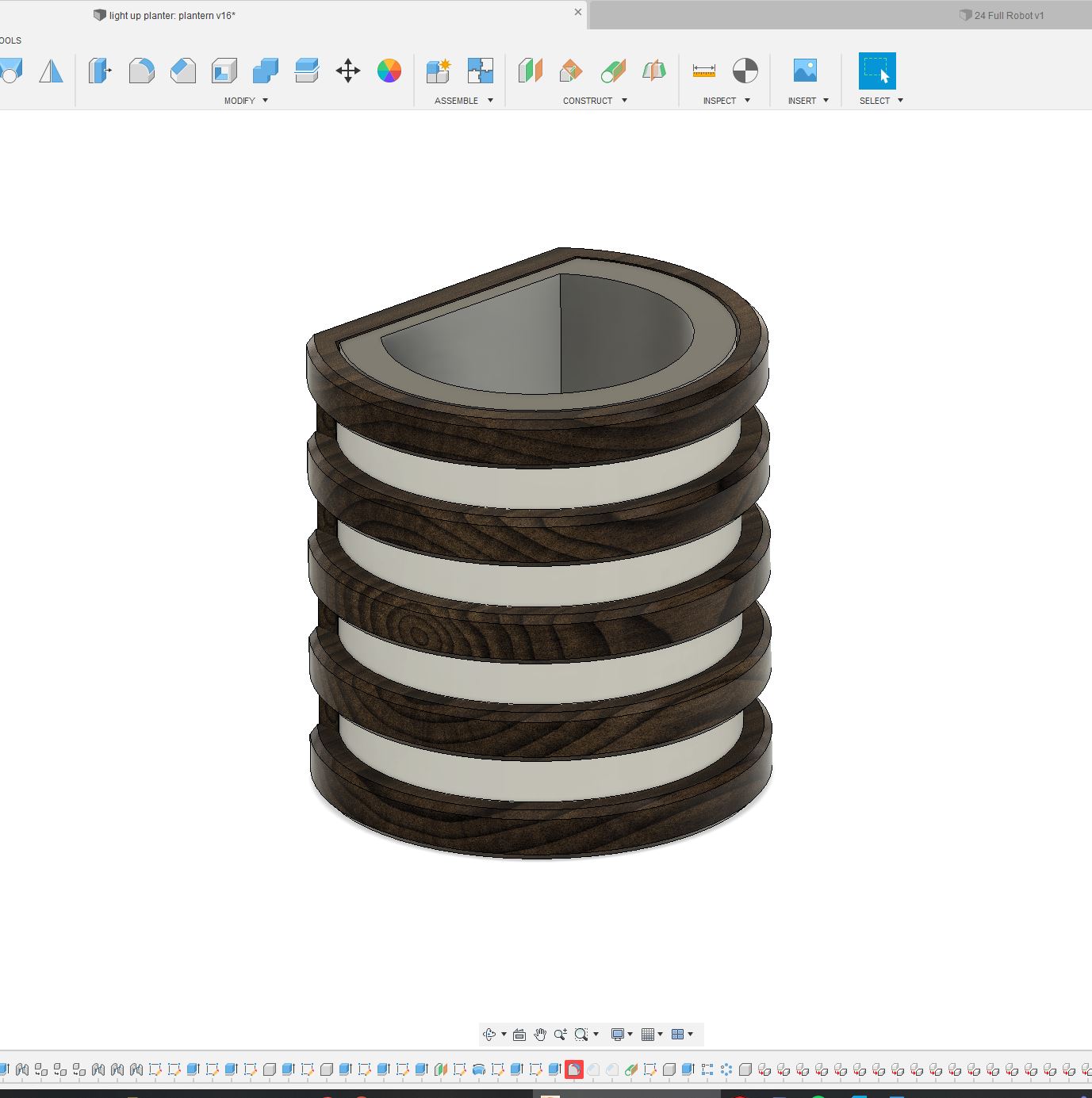
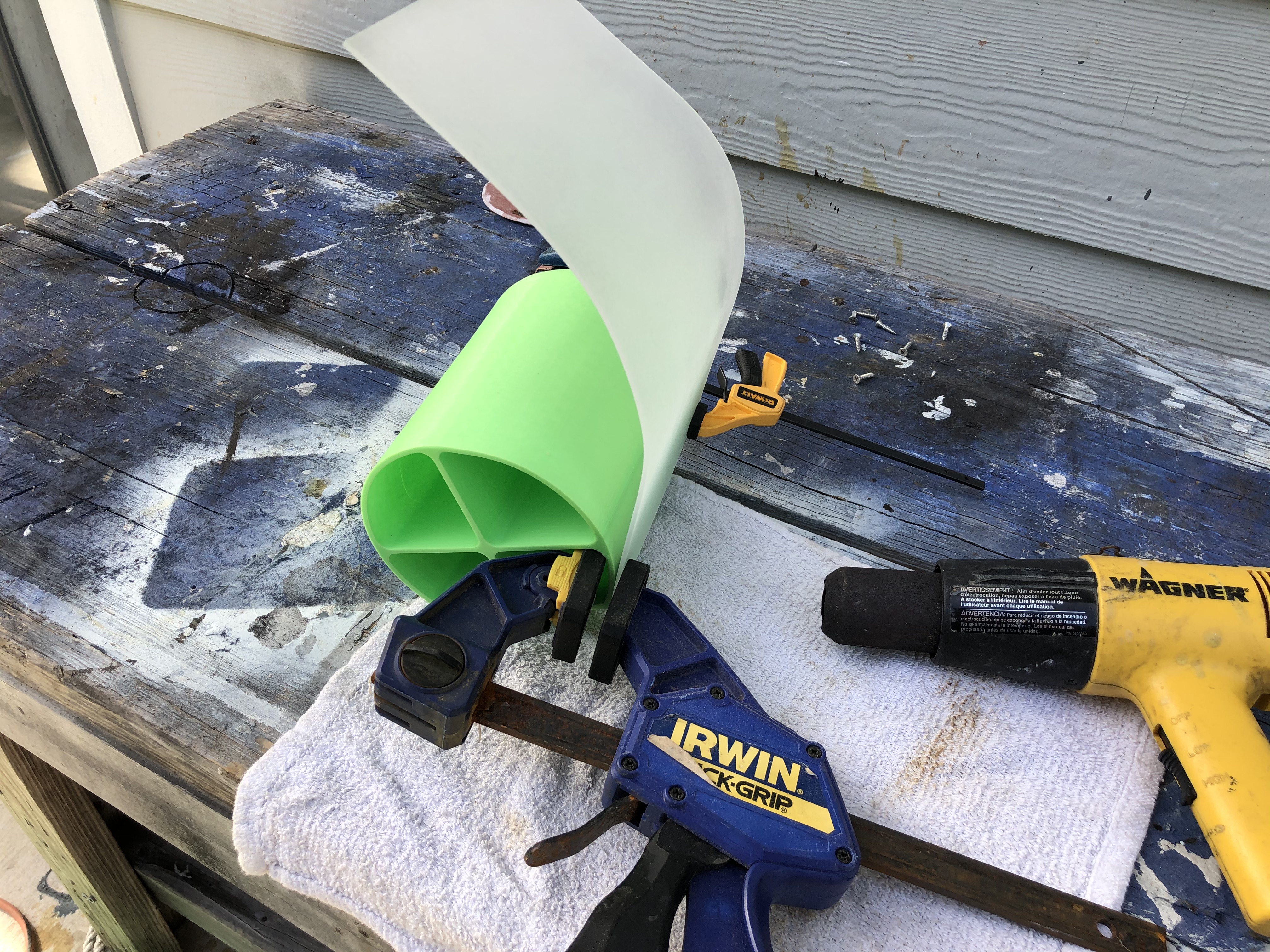
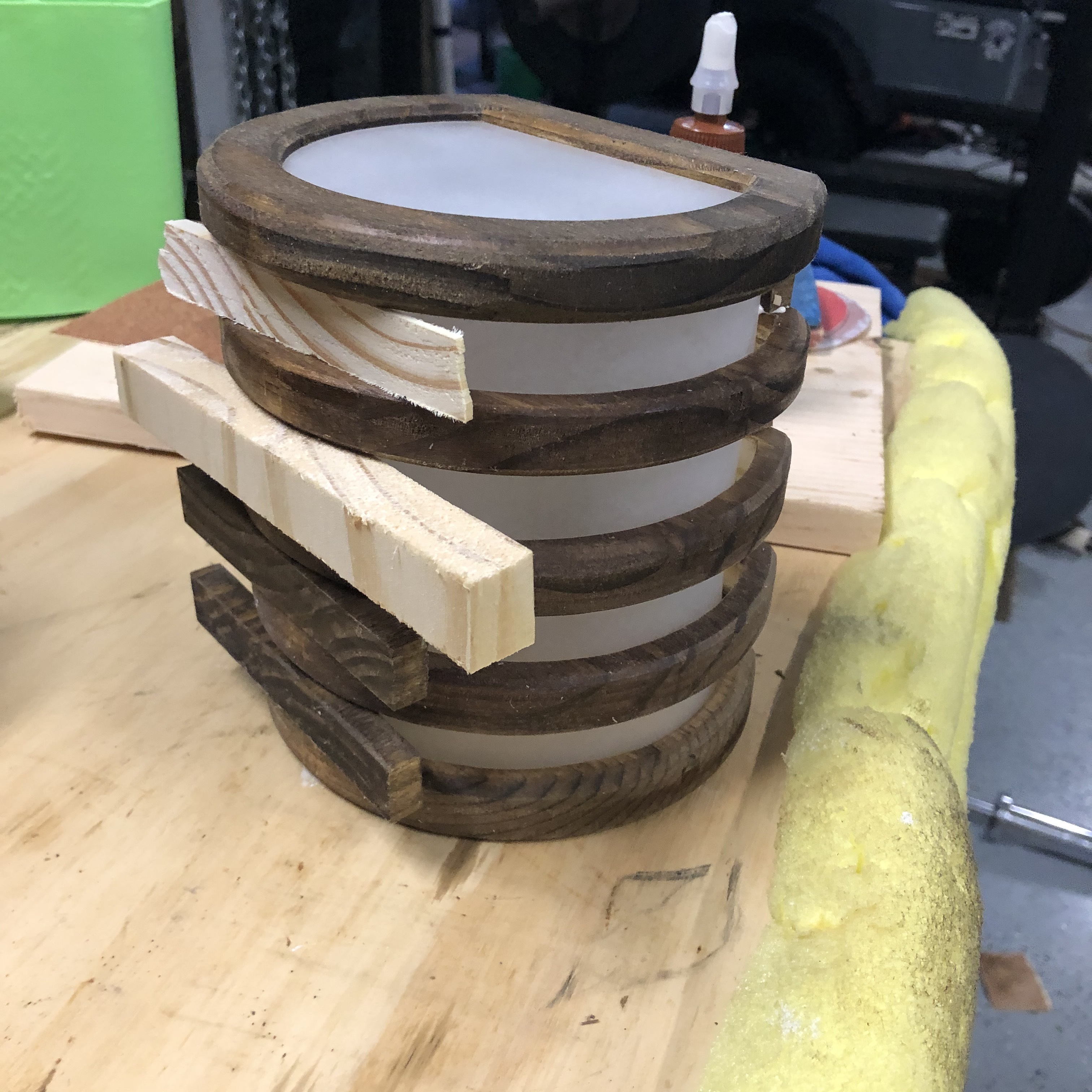
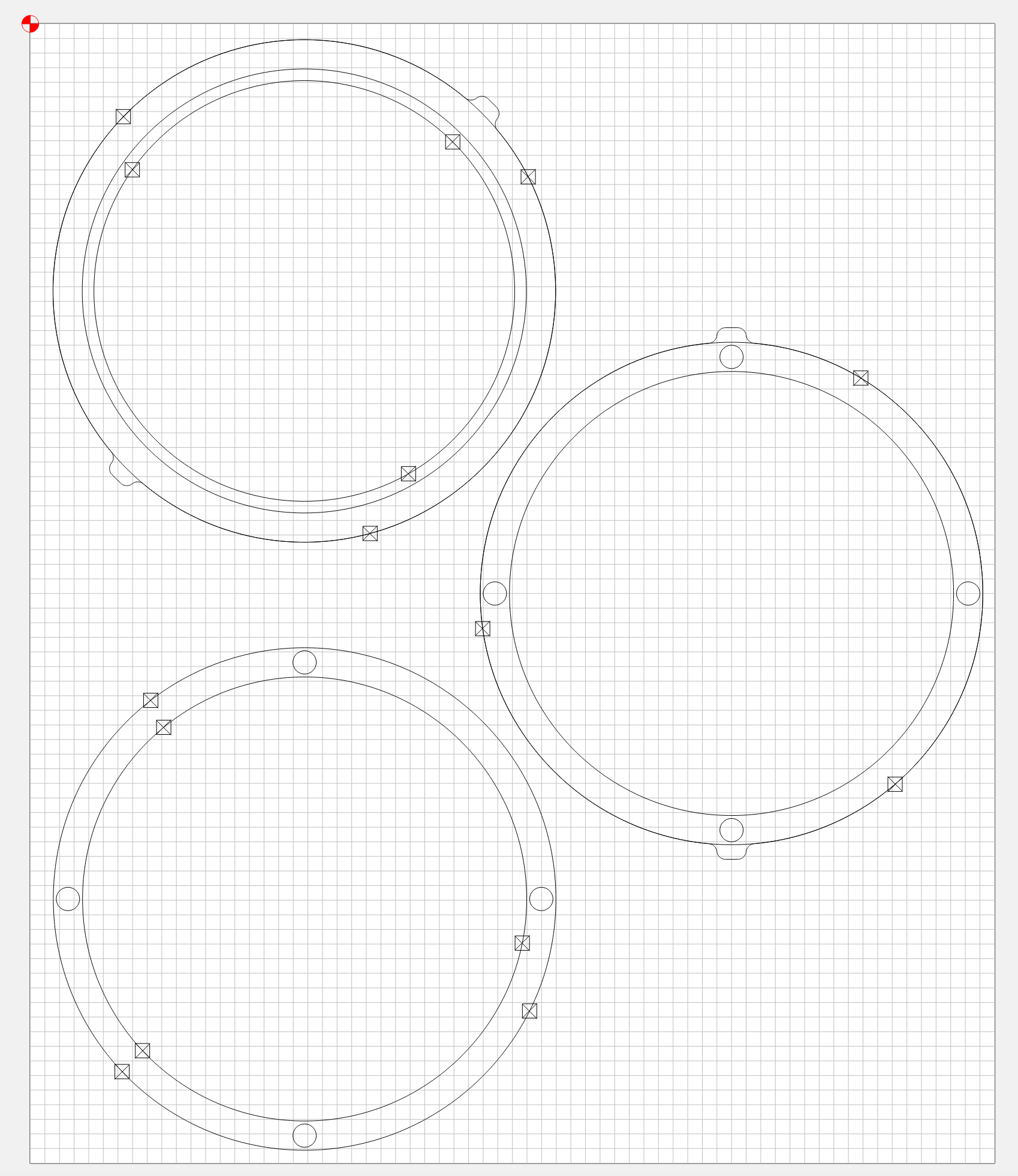
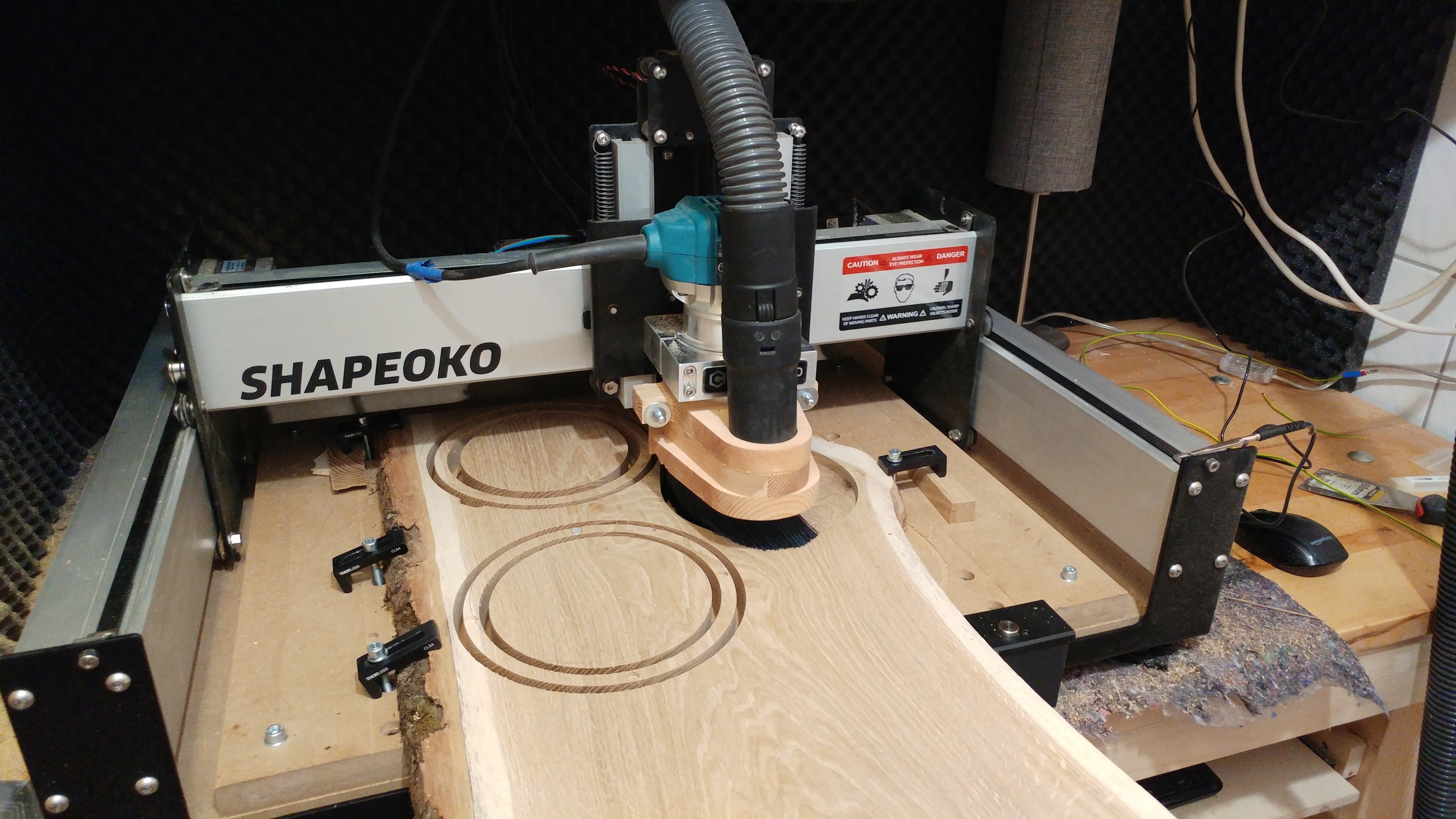
These LED planters were something I wanted to make years ago but just never got around to, this months theme was the perfect excuse to try and finally make them. Theyre made up of 5 stained pine rings, a bent and sanded sheet of acrylic, a 3d printed pot and some sweet individually adressable LEDs. They also house real plants and can be mounted to the wall!
They were an absolute pain in the butt to pull off and I honestly didnt think I was gonna meet the deadline for the contest, but I was able to rush a few things and get them finalized today.
F360 link: https://a360.co/3mUjk1o
CutRocket:https://cutrocket.com/p/5f6fbb1e136fe/
I dont have enough time to write a fully detailed build report today but Ill post all the pics of the build process and try to add a few comments.
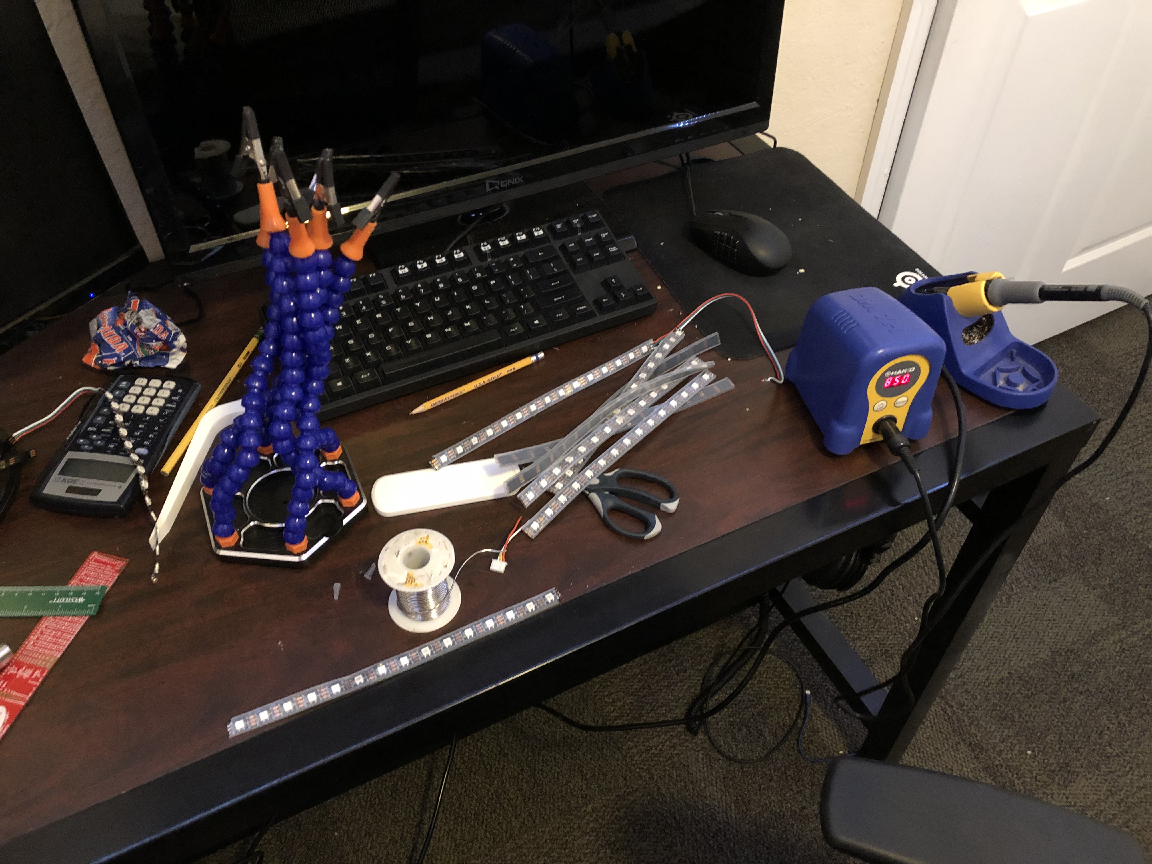
The LEDs are ws2812b individually addressable 5v LEDs, which means each pixel operates independantly of all the others. This allows for some sweet multicolor effects which you can see in the below video:
I designed them from scratch in fusion 360 and also did all the CAM in fusion 360. Just like last months contest I was able to use the new manufacturing model feature and the arrange tool to easily arange all the components to be cut with the shapeoko.
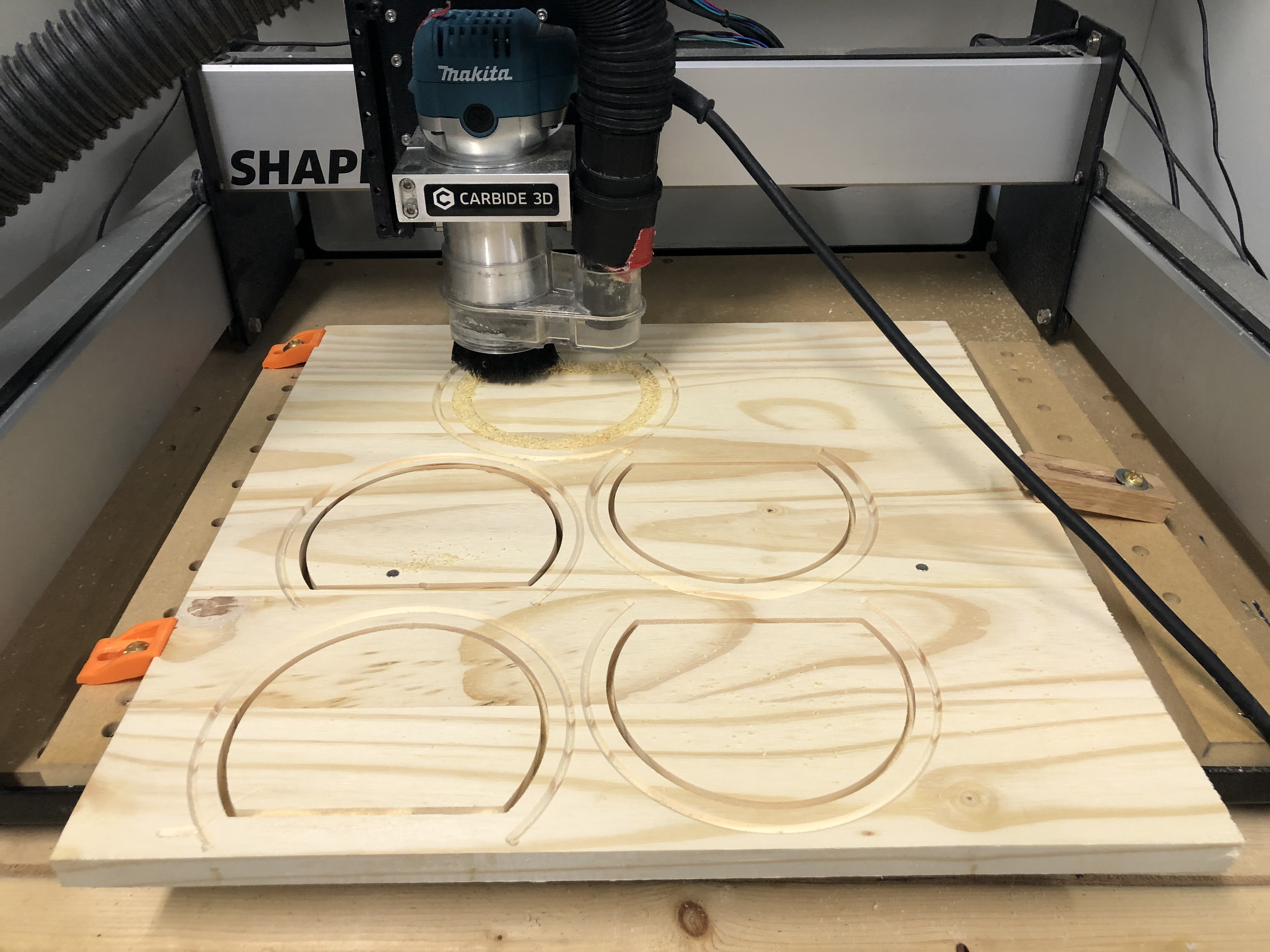
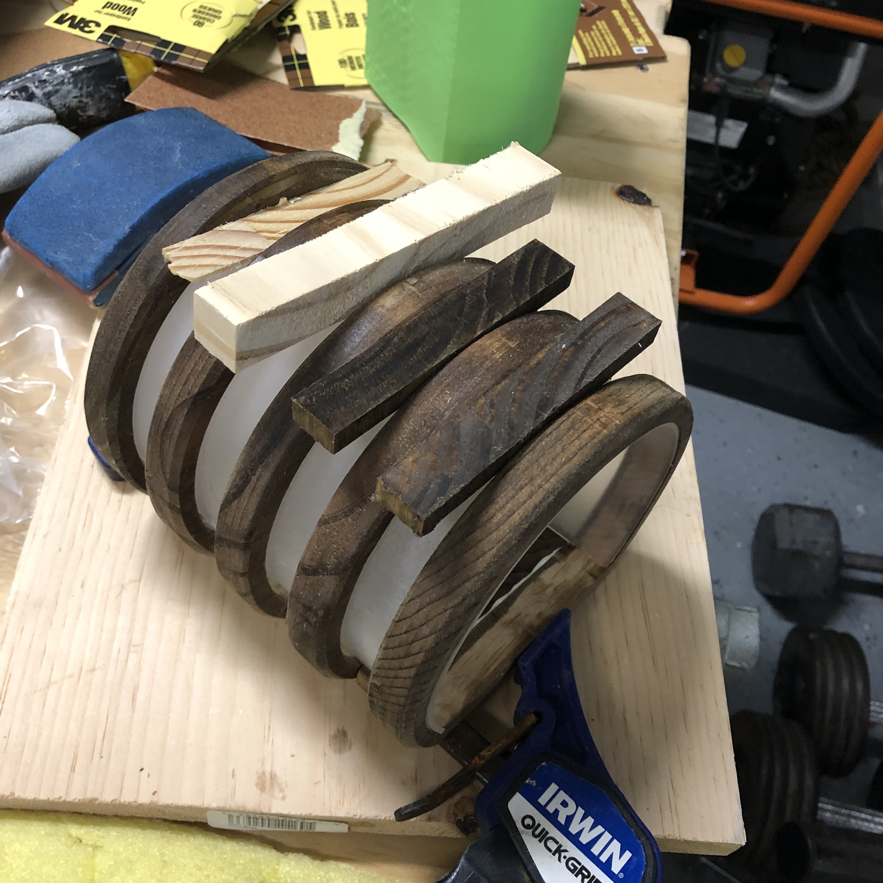
I started the build by cutting the pine rings and spacers that would eventually be glued together to makeup the wooden frame. I used dowel pins and multiple side machining to add a nice chamfer to both sides of the ring. Using multiple sided machining added a lot of time to the process but I’m fairly happy with the results, the chamfers add a lot of depth and detail to the rings.
Had a mini causualty when I accidentally ran through a clamp screw
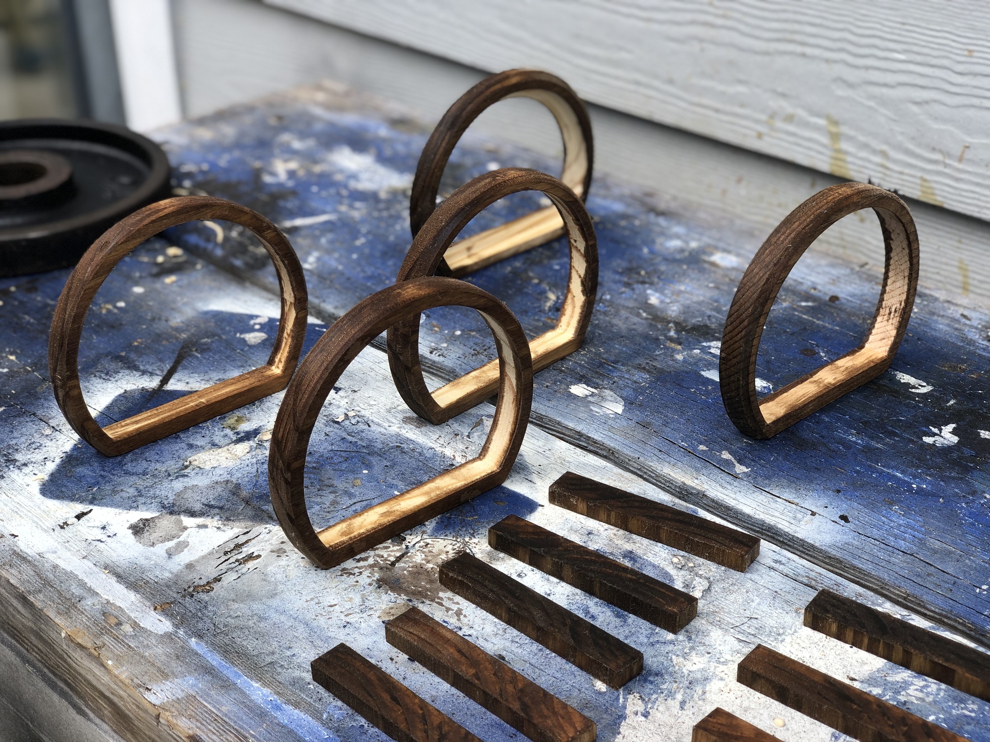
Next up was sanding and staining for the rings.
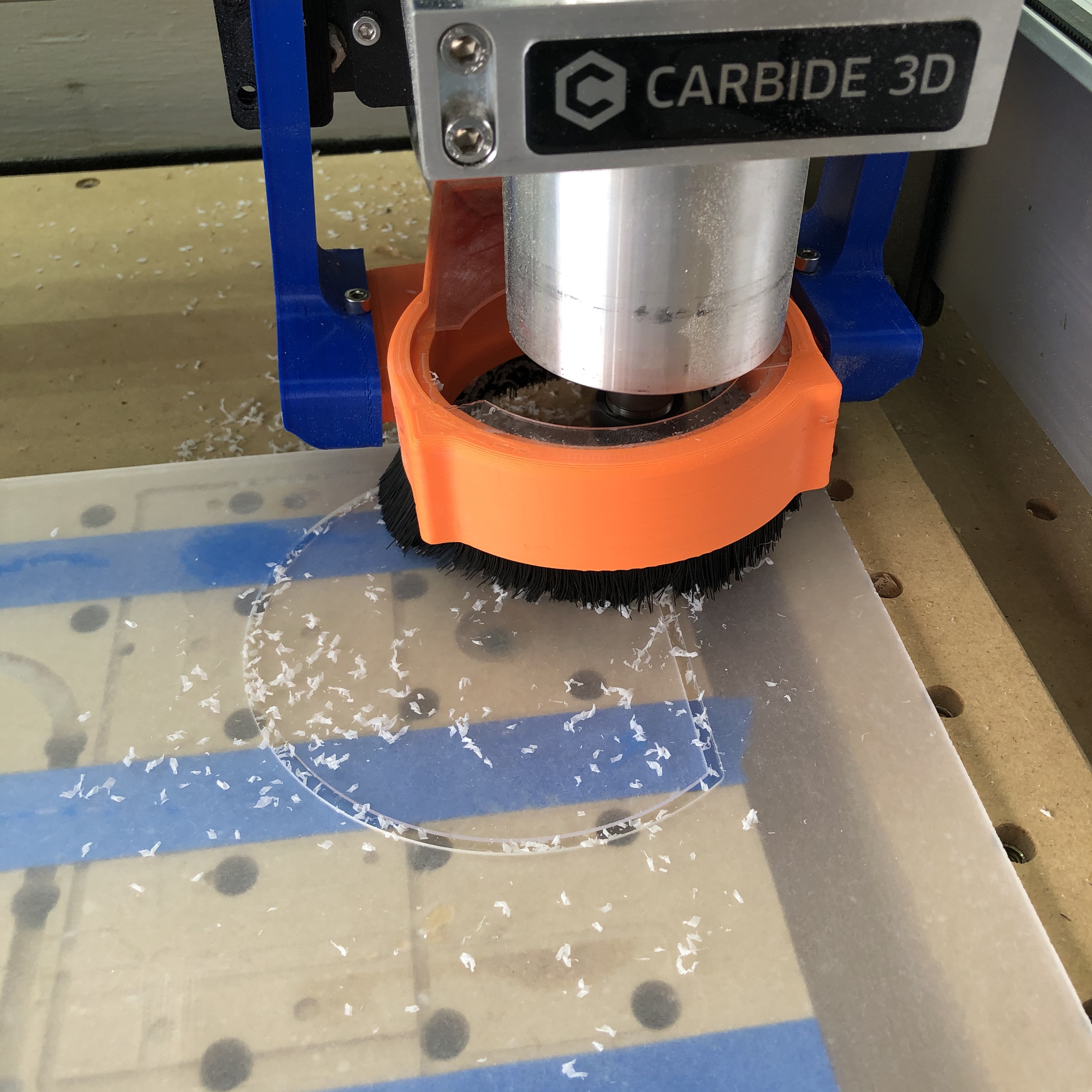
Now its time to move on to the acrylic.I started by sanding the .093" sheet to give it a frosty matte finish. This will difuse the lights from the LEDs and make it so you cant distinguish individual pixels.
After that was cutting the acrylic, which was extremely easy on the shapeoko
Then I heated and bended the cut acrylic using a custom fixture I 3d printed out of PLA. The PLA almost couldnt stand the heat and started to warp but it was able to get the job done for the two sheets.
I ended up using some of the extra rings I made in order to finish up the bending and keep the acrylic at the perfect roundness.
You can see here how the PLA was starting to get soft. If I do this again I’ll use ABS or nylon.
What happens when youre too forceful and dont apply enough heat.
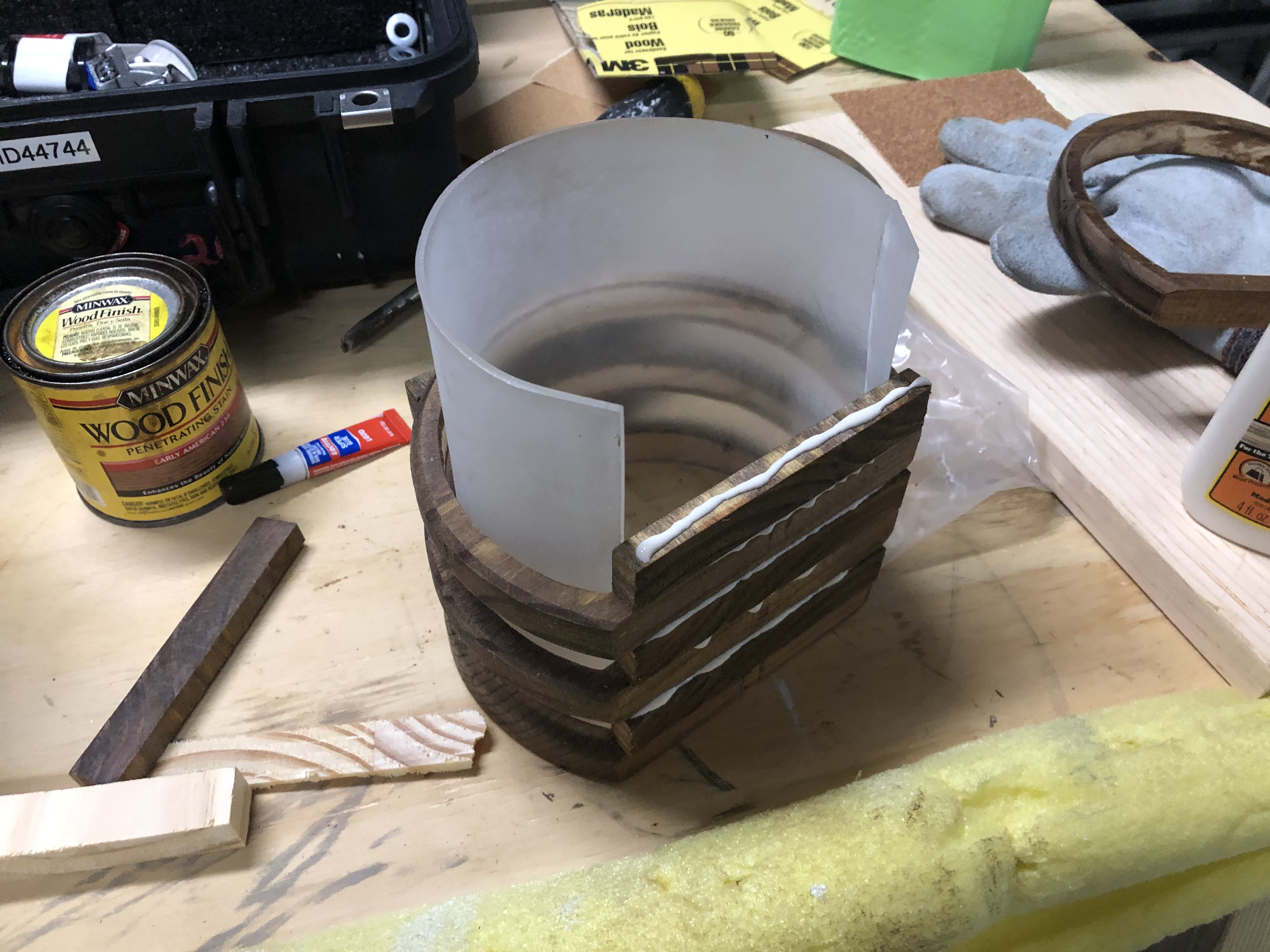
Now its time to glue it all together. I used wood glue for the wood and super glue to hold the acrylic to the bottom. The rounded acrylic fit fine with just a press fit. I also used some scraped wood blocks as spaces to make sure the rings stayed parallel.
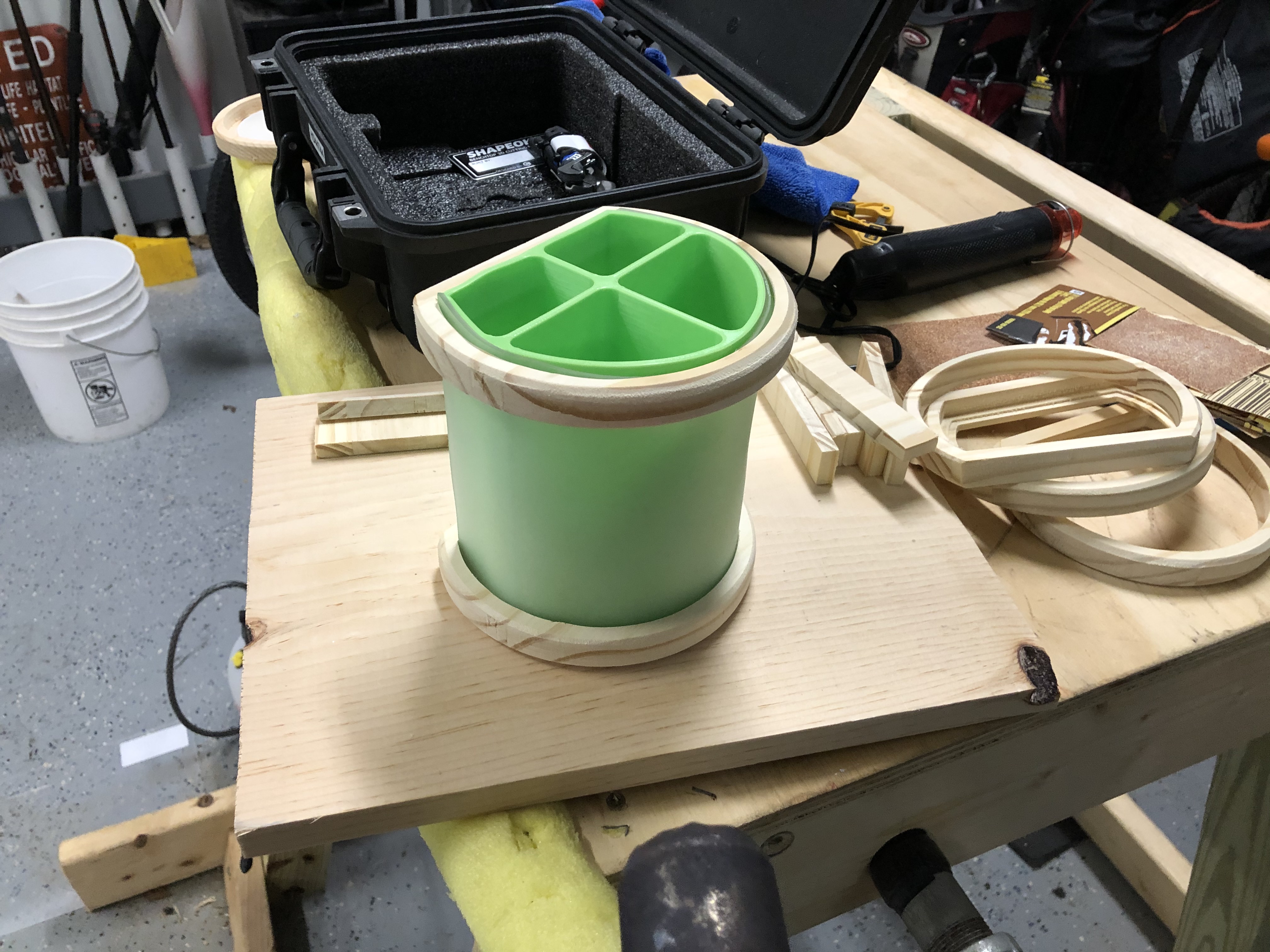
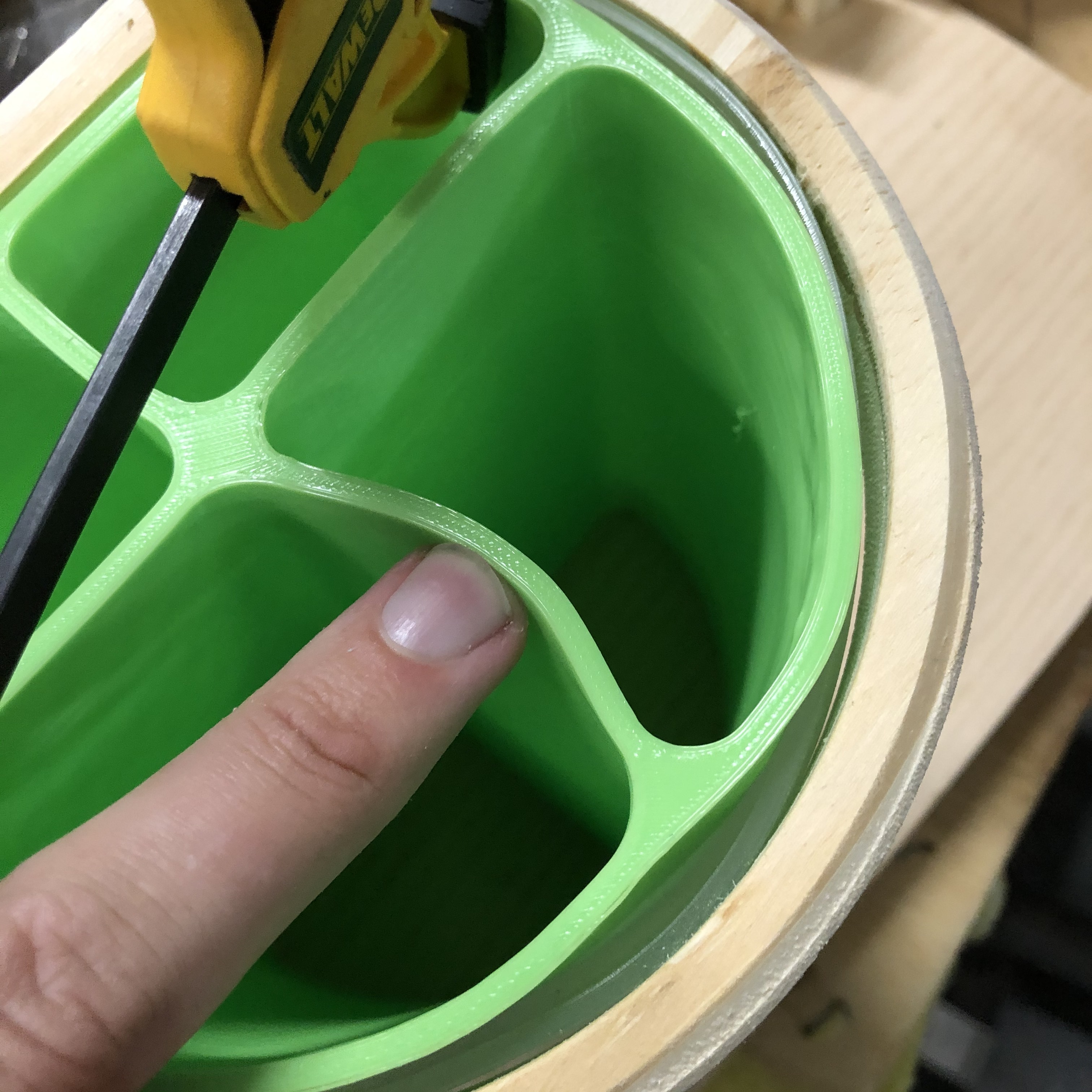
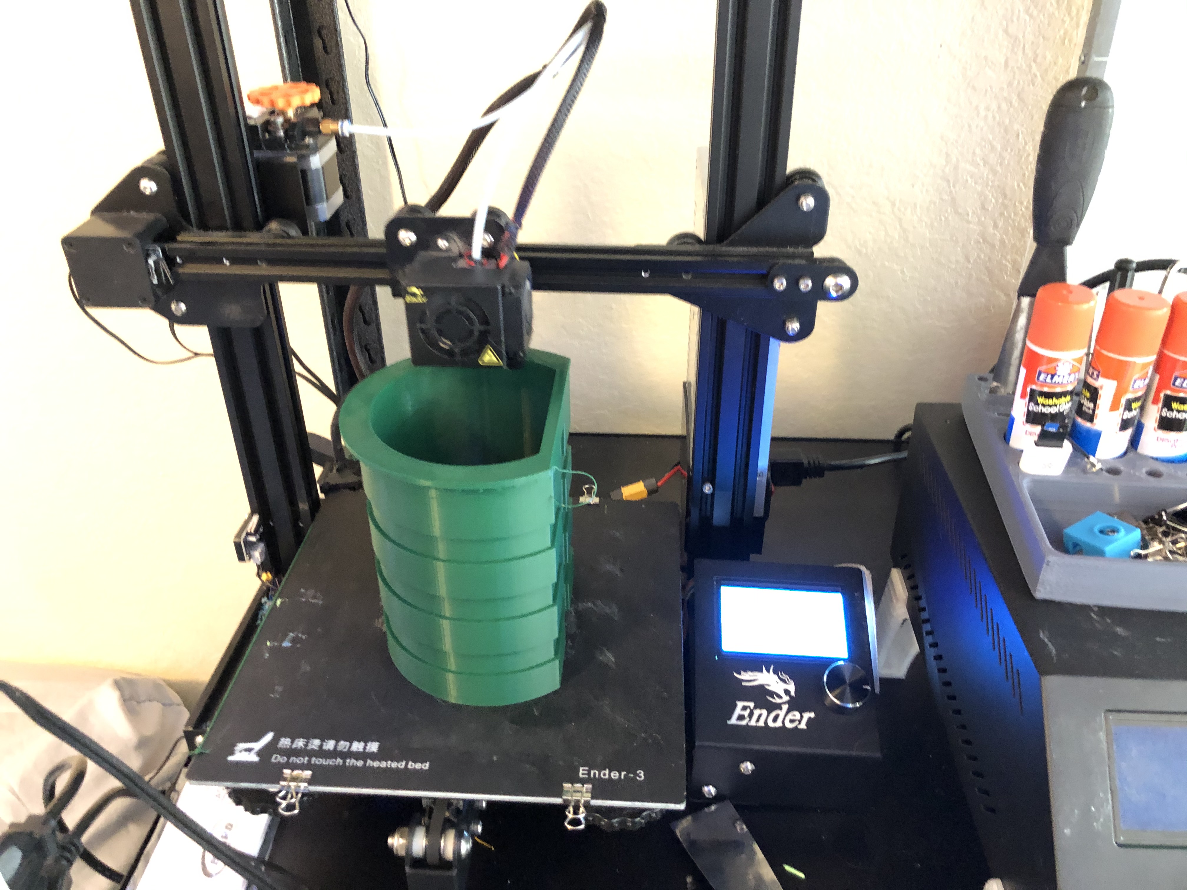
The final part was 3D printing the pot to actually hold the plant. I designed this part to have grooves to make it easy to hold the LEDs and have them line up with the wooden rings. The LEDs arent actually visable in the final design, theyre all hidden behind the wooden rings in order to hide the individual pixels and create a more seamless design. If you want to replicate this without a 3d printer you could just use a large PVC pipe.
I ended up using hot glue to glue the lights into the grooves of the 3d printed pot.
The pot fit snug into the wooden body and all I had left to do was buy a plant and plug it in!
They even look good with the lights off!
Very nice.
Bear Down! (from a UofA alum.)
Thank you! I’m a “house divided” - one daughter went to Arizona State and the other to University of Arizona.
Silly me was worried, but not anymore!
Awesome, awesome entries…
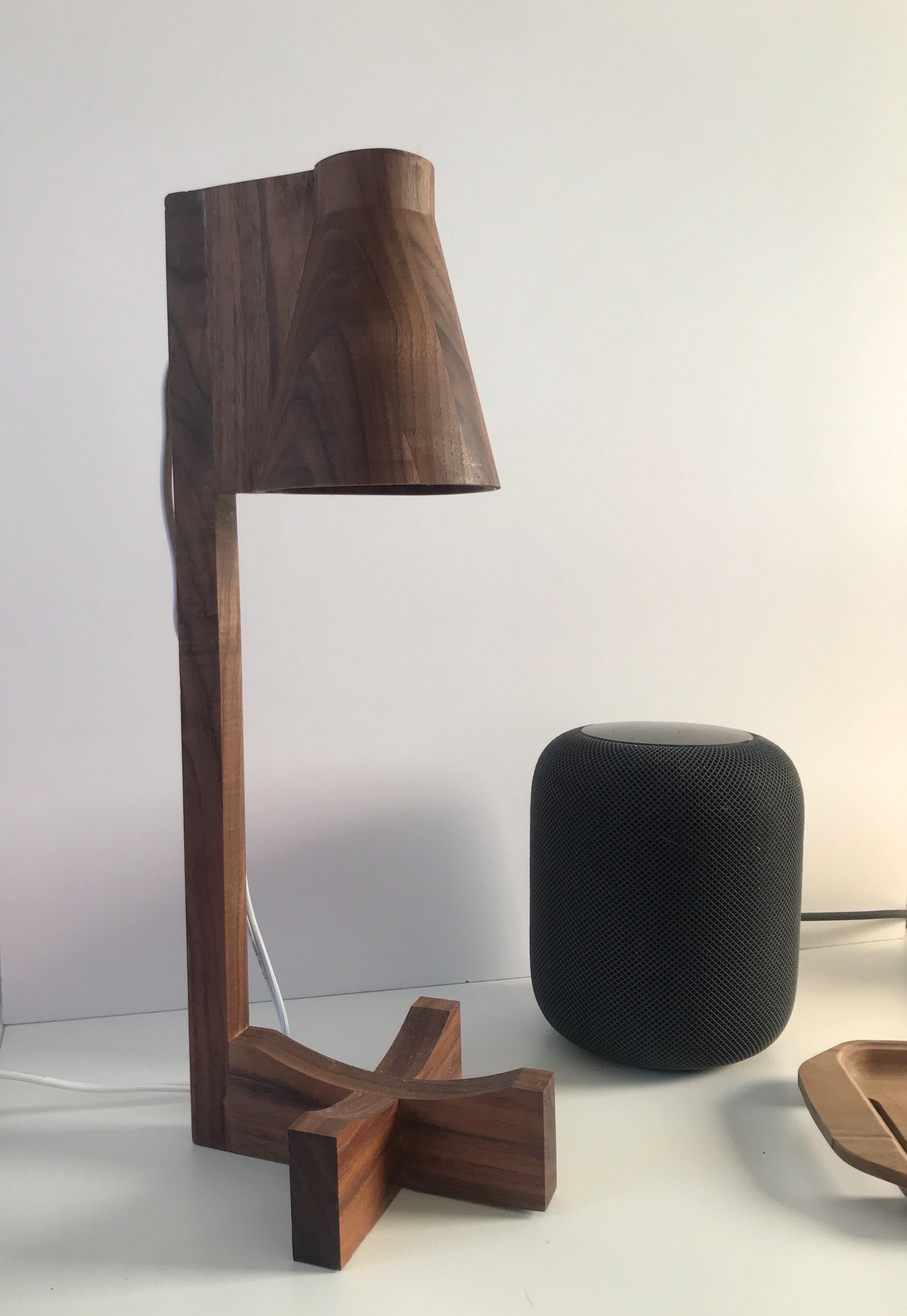
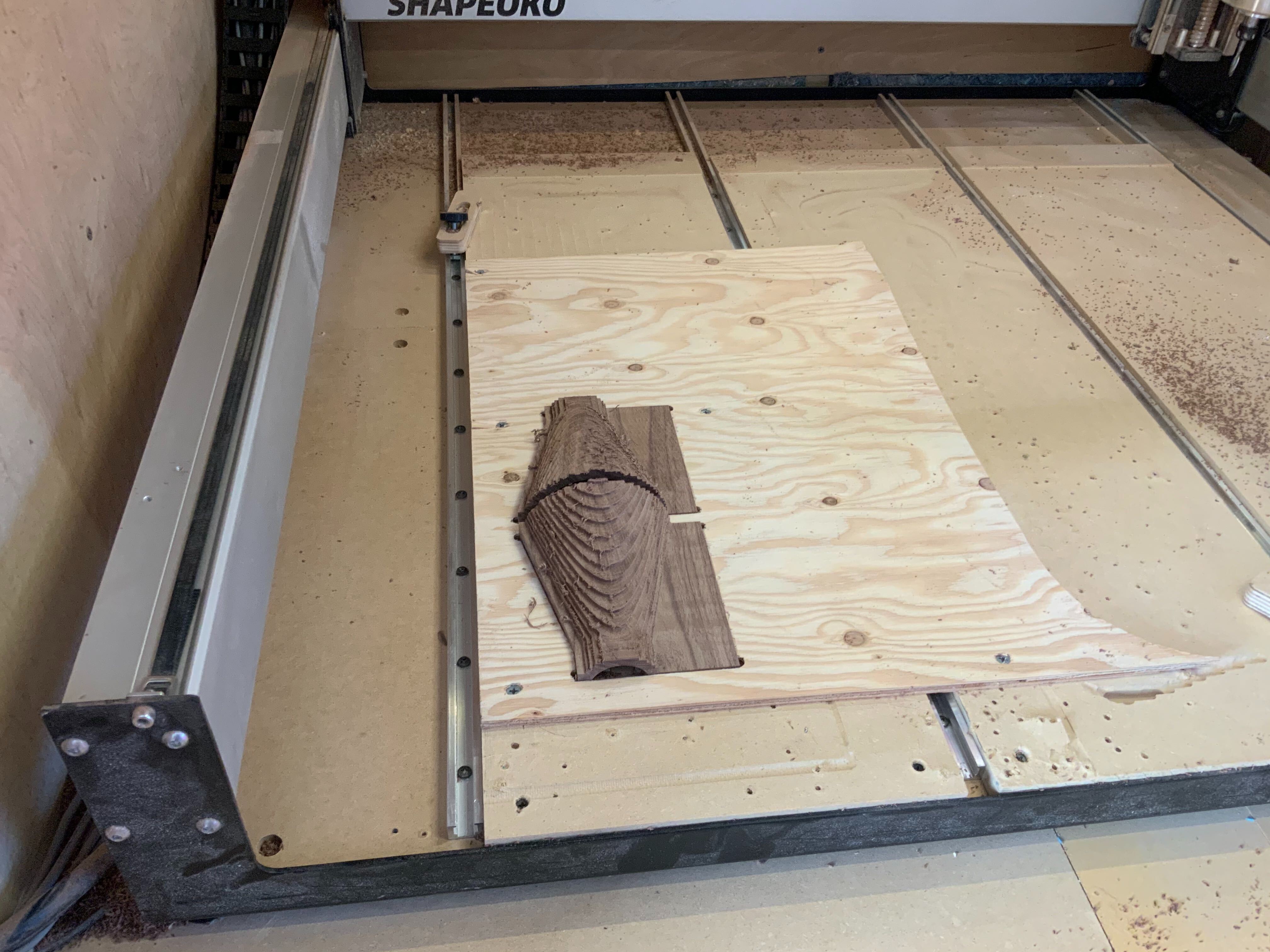
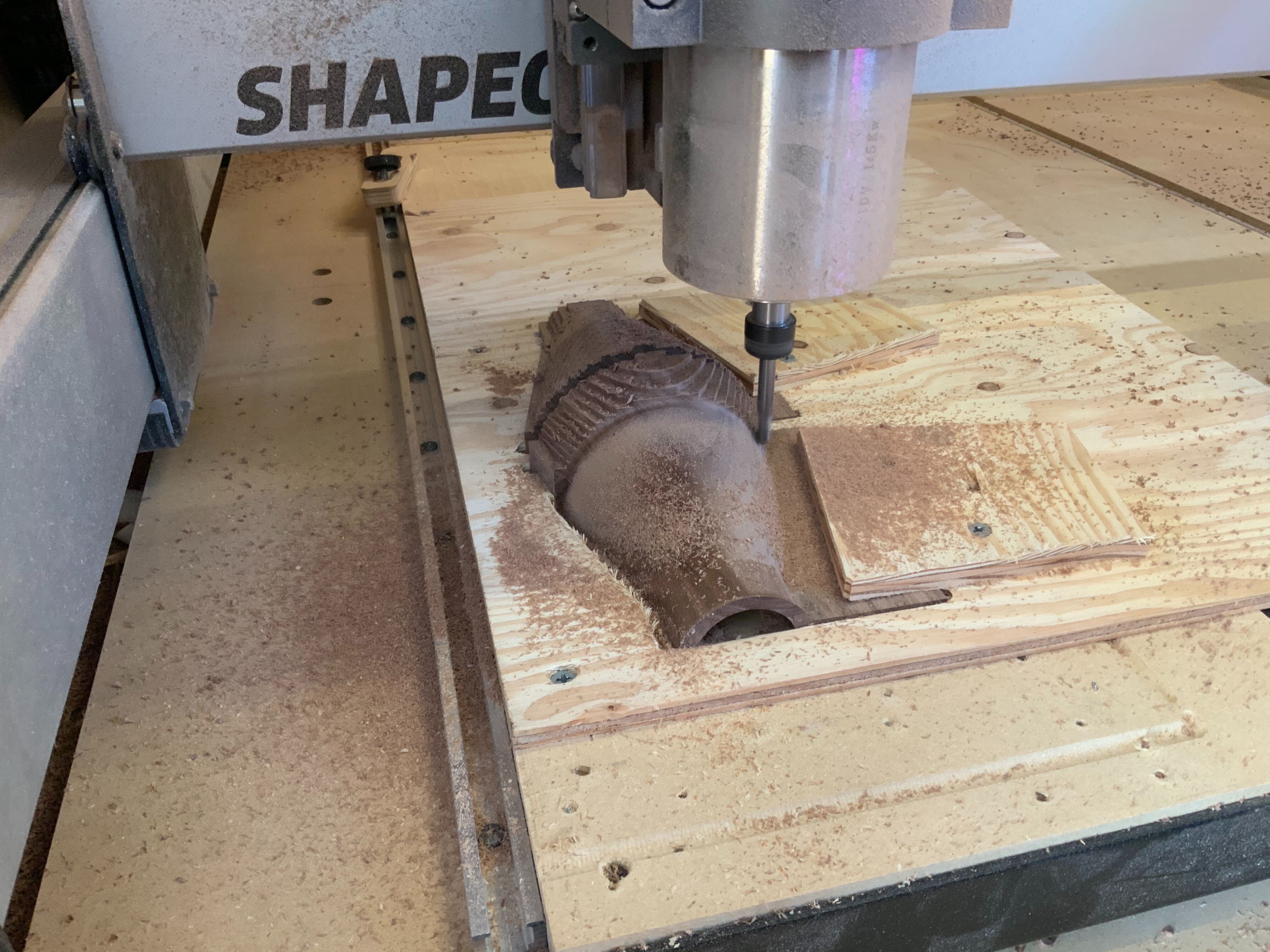
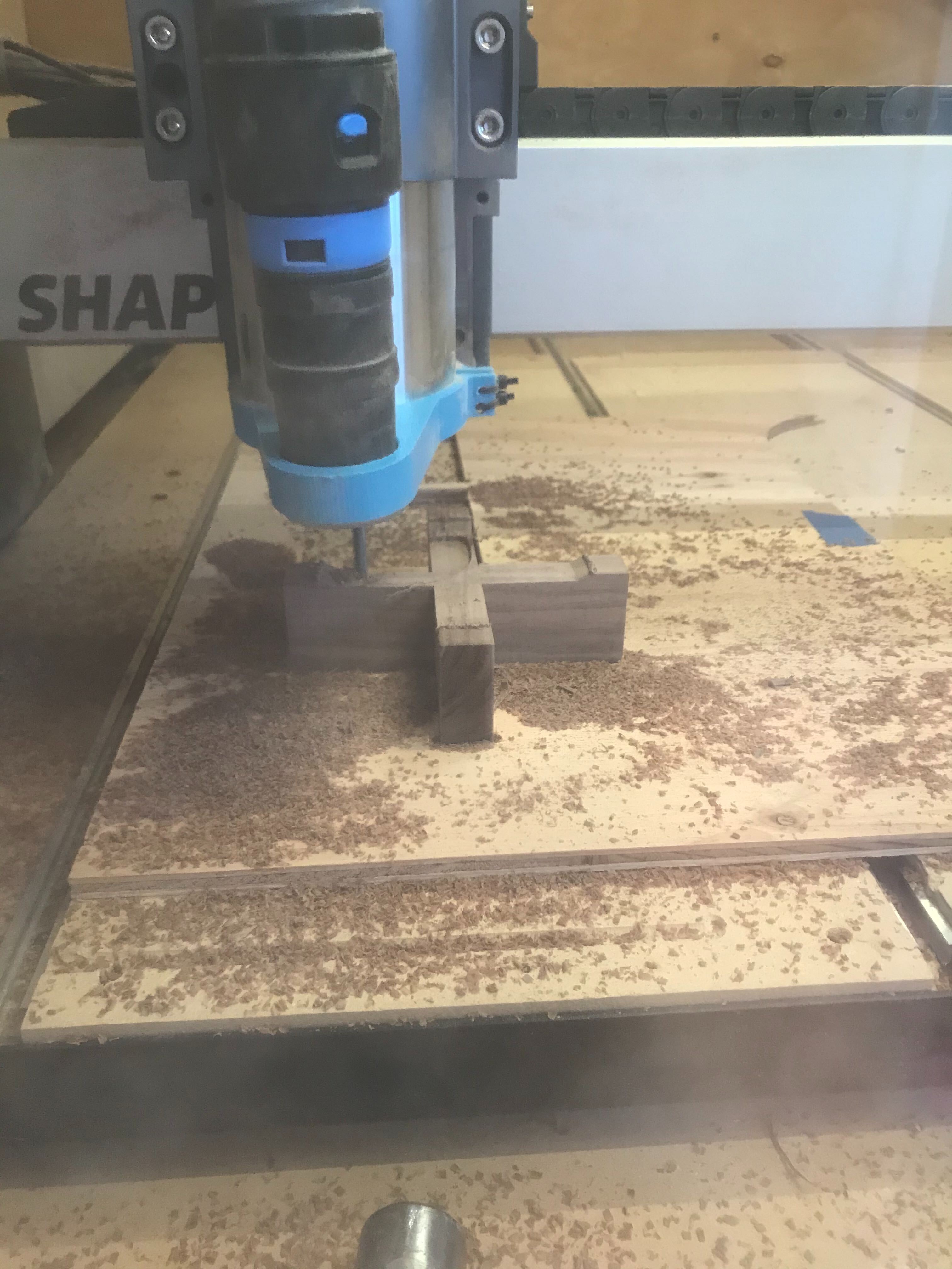
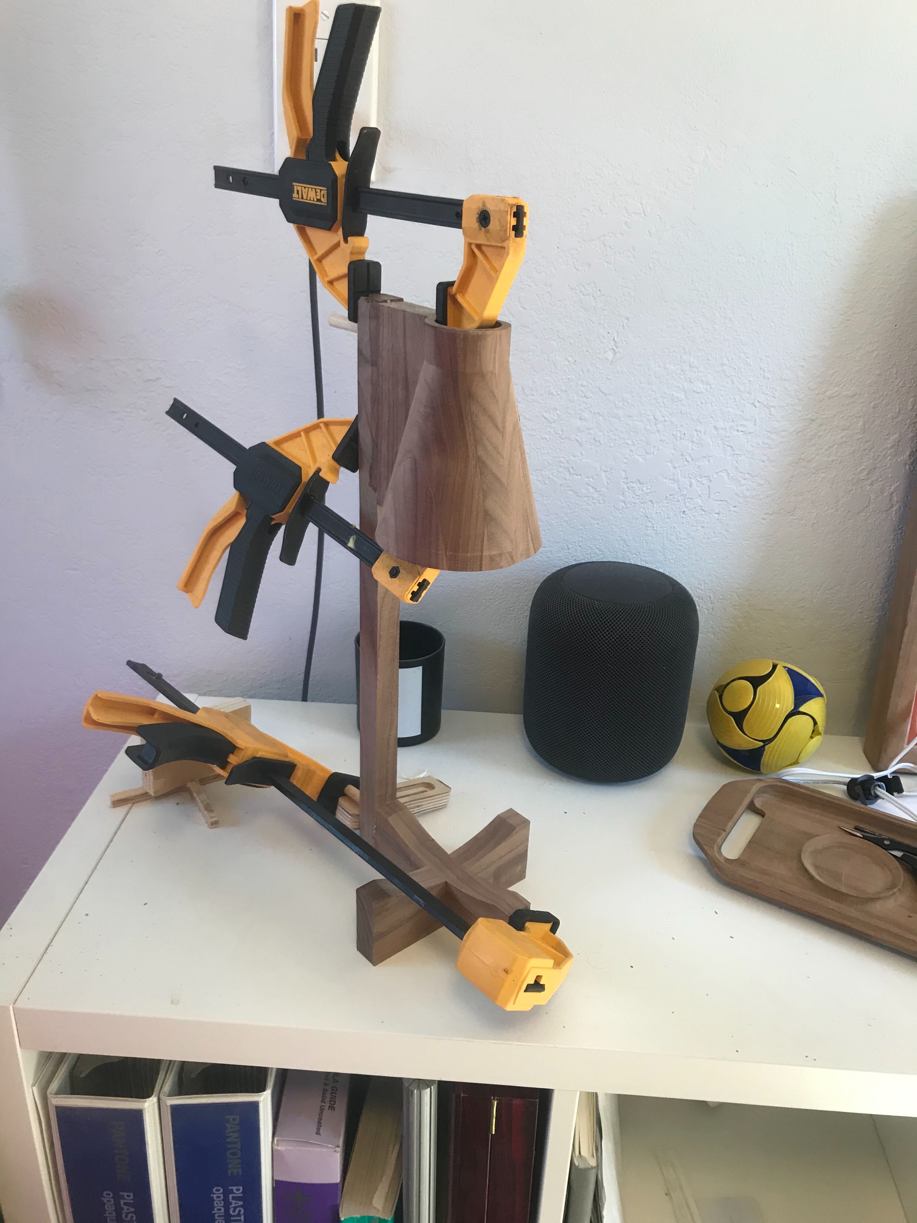
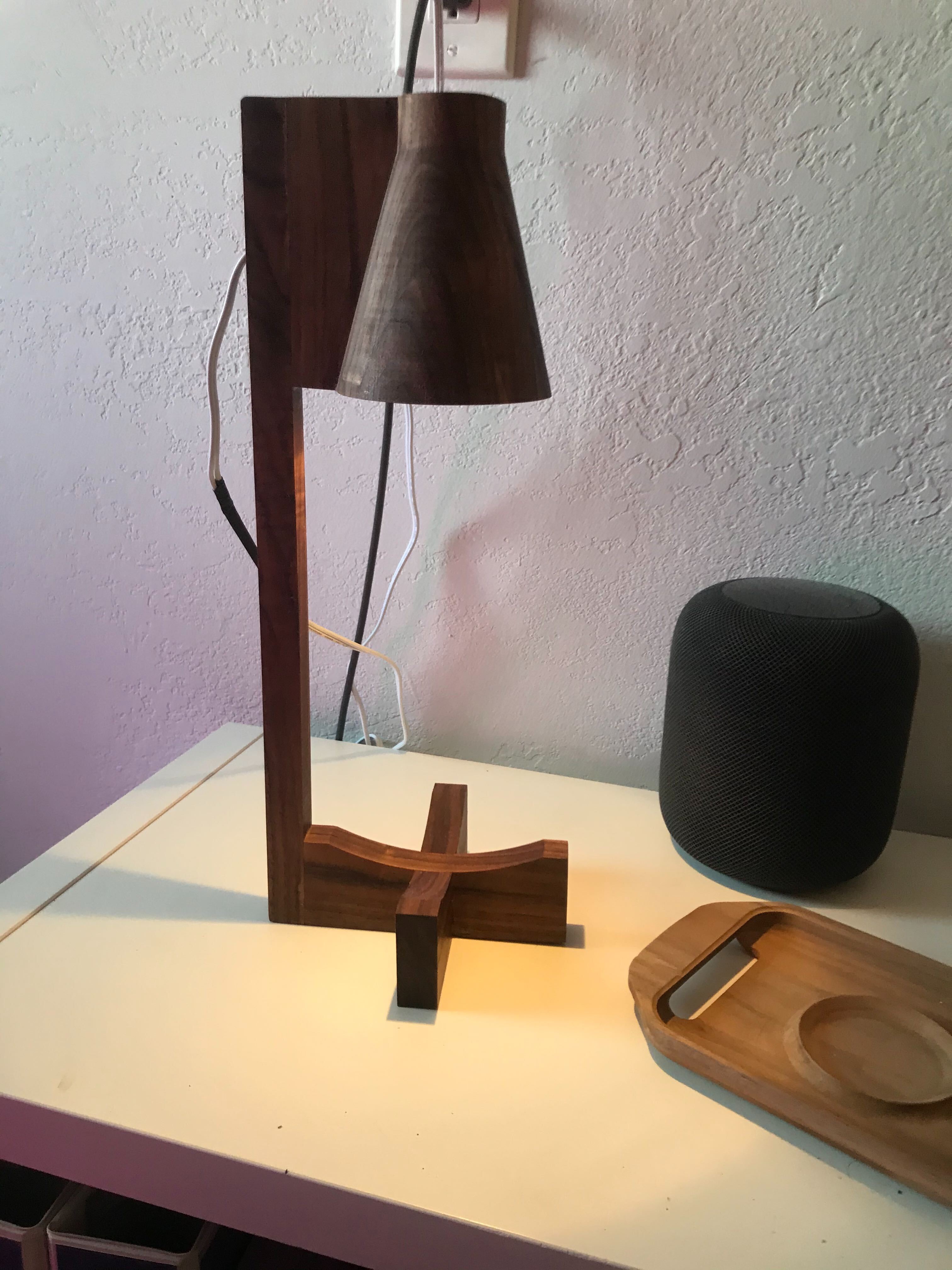
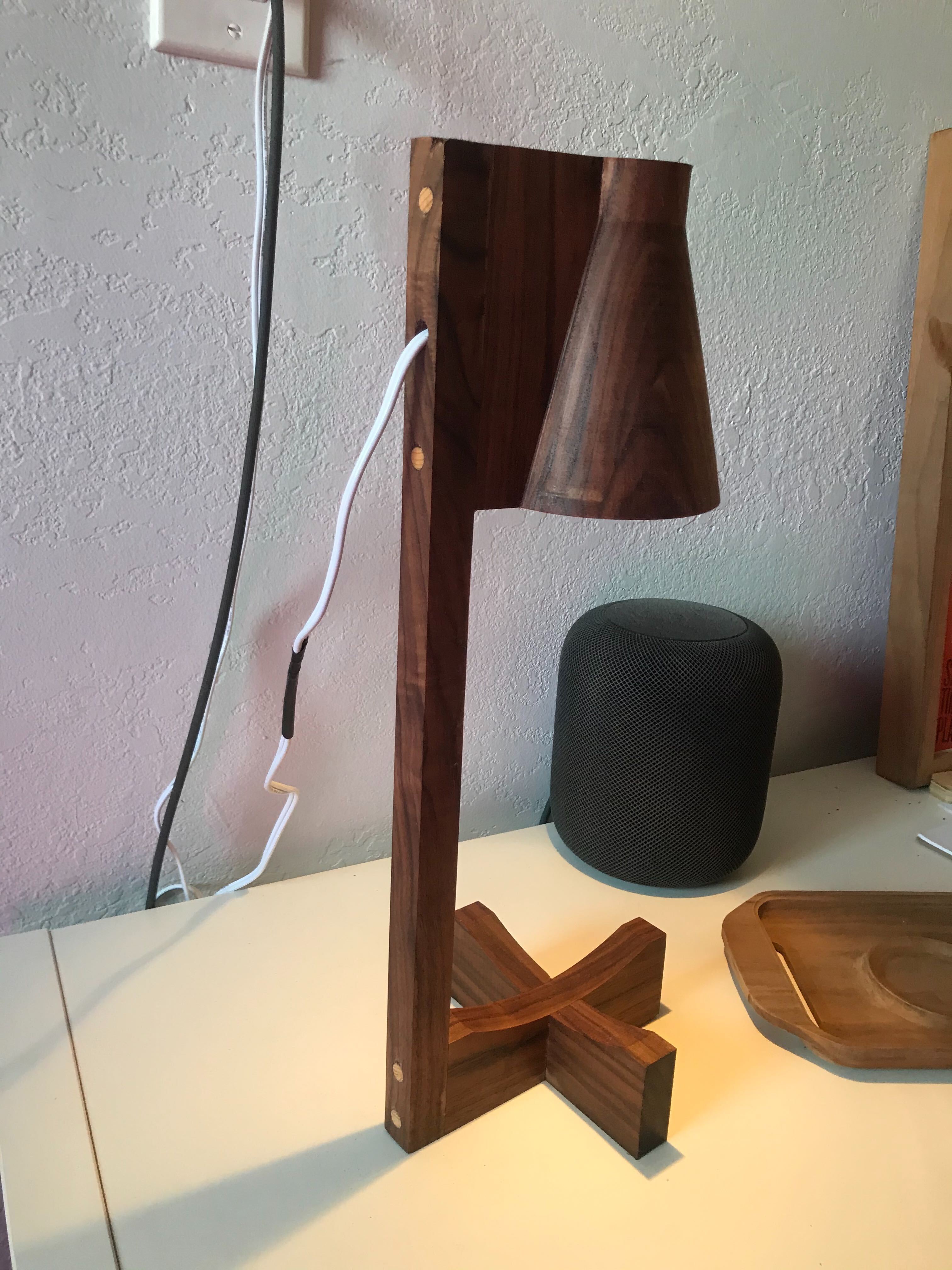
Walnut Lamp!
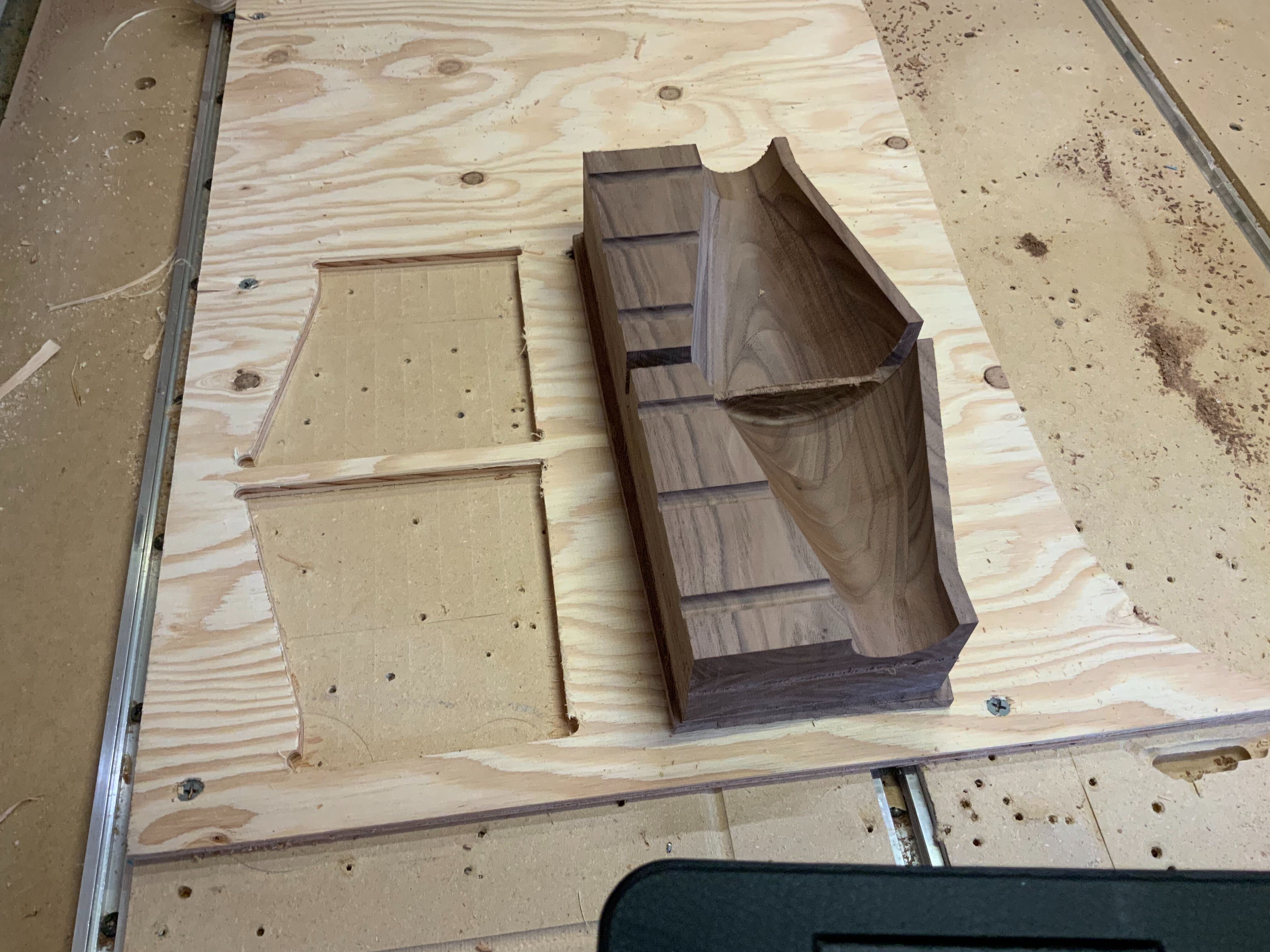
This entire project could be categorized as figure it out as you go. I glued up this block before I fully knew where I was going, so I had a little more stock material than I needed. Lots of wood Chips!
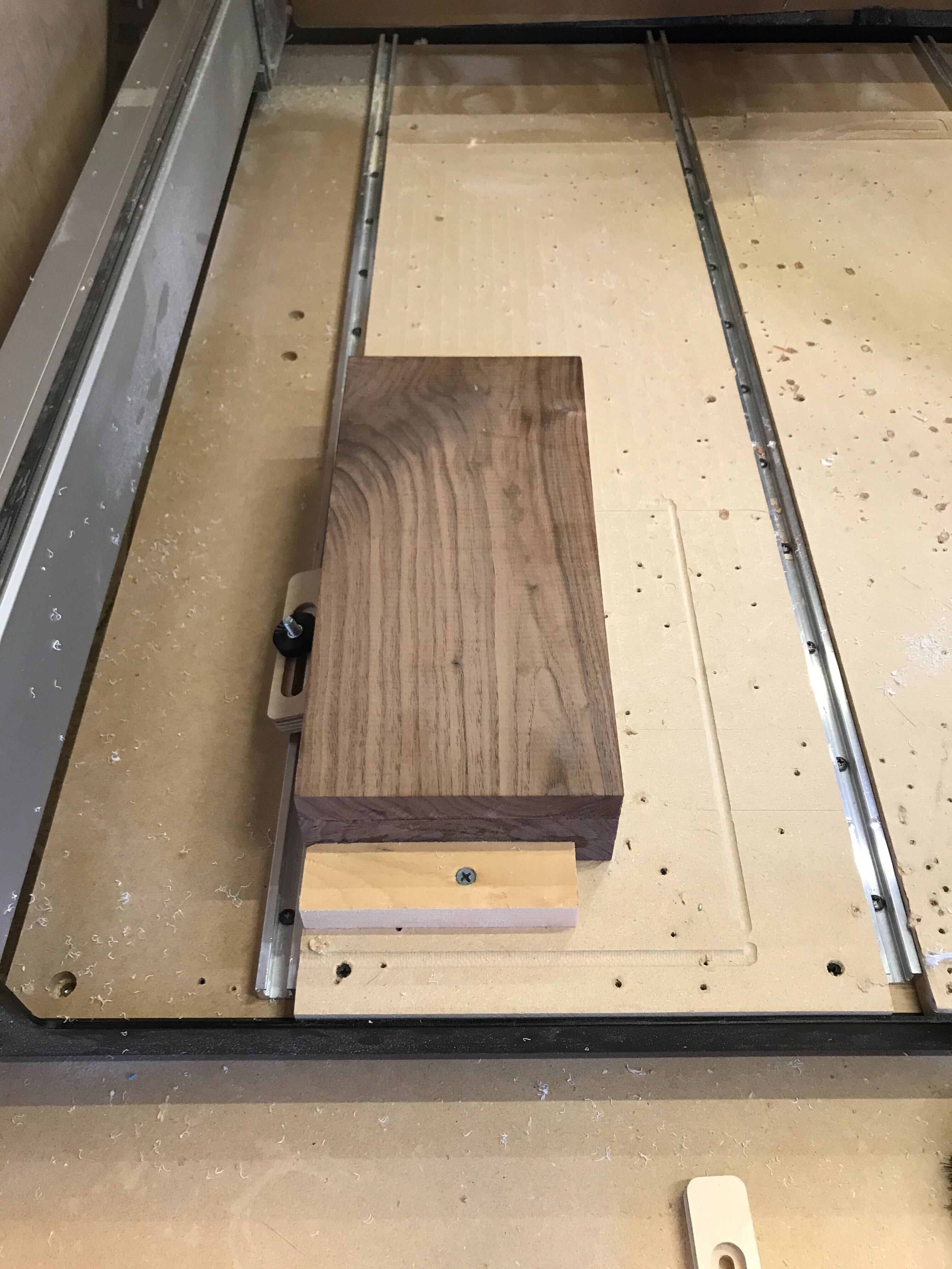
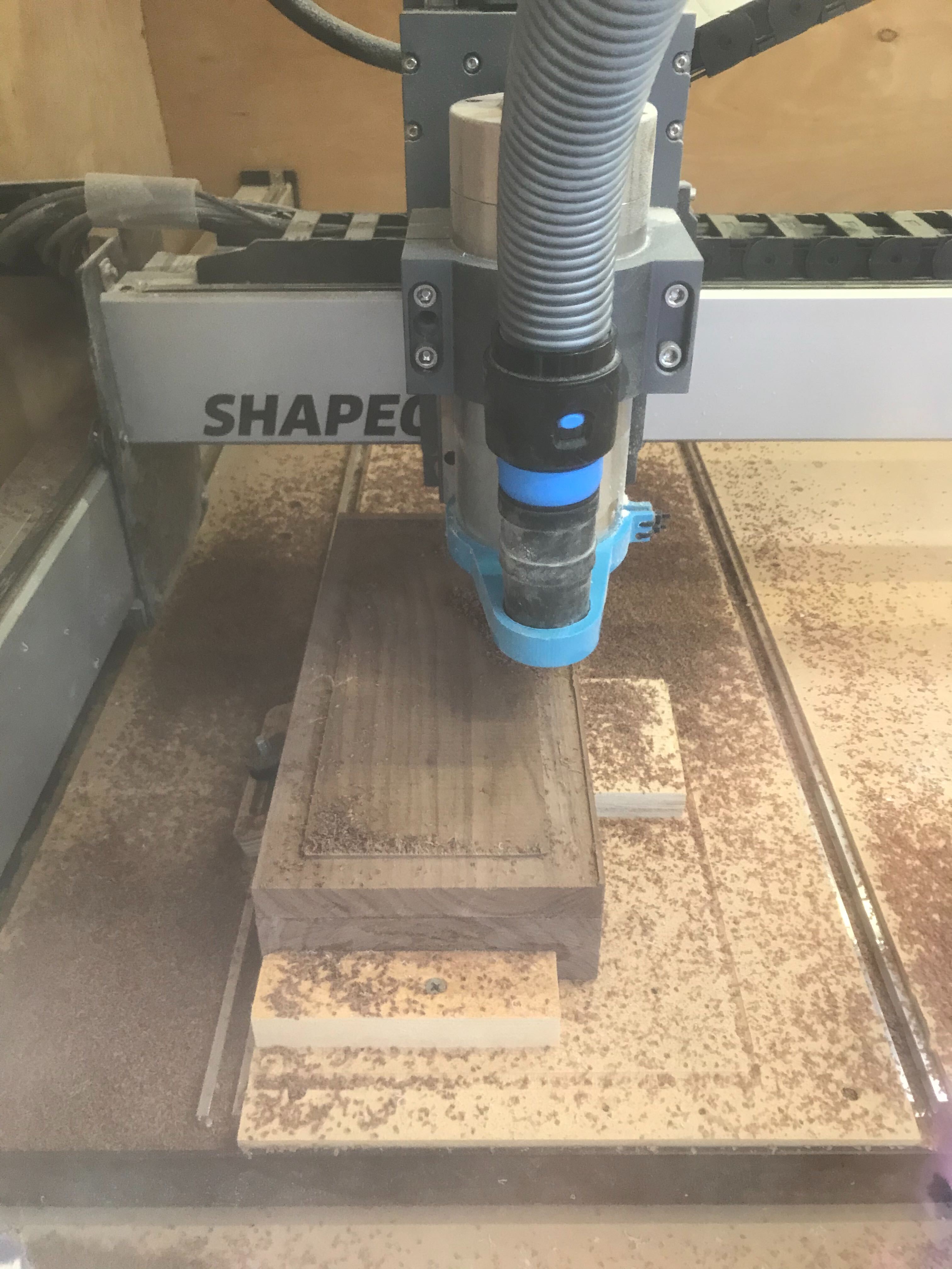
 So I milled a quick pocket in some scrap wood to locate it on the machine and hold it in place along with some double stick tape.
Here is the CAD file.Walnut Lamp.stl (162.7 KB) https://a360.co/3cCNEJ9
cut rocket: https://cutrocket.com/p/5f70b6cc67d1a/
Thanks for the challenge, and for checking out my project!
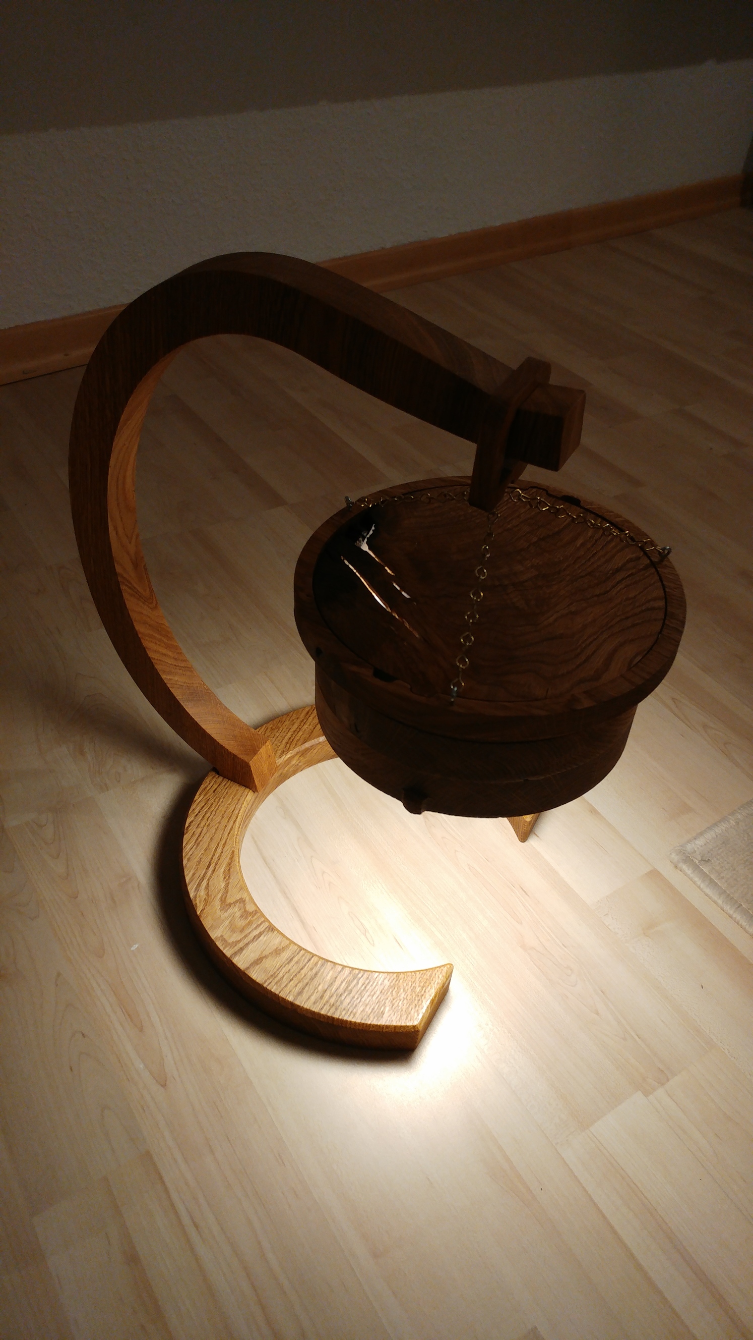
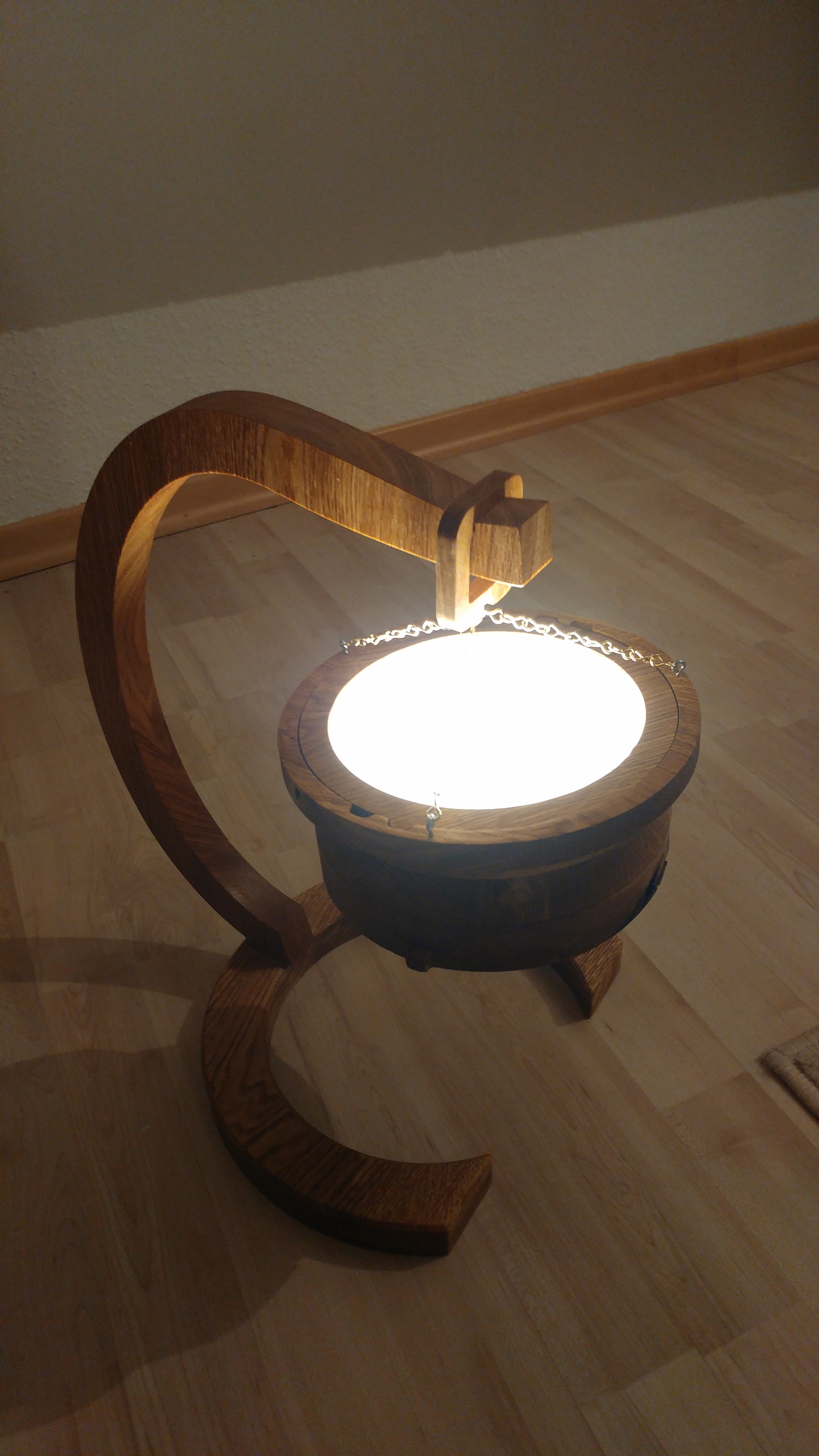
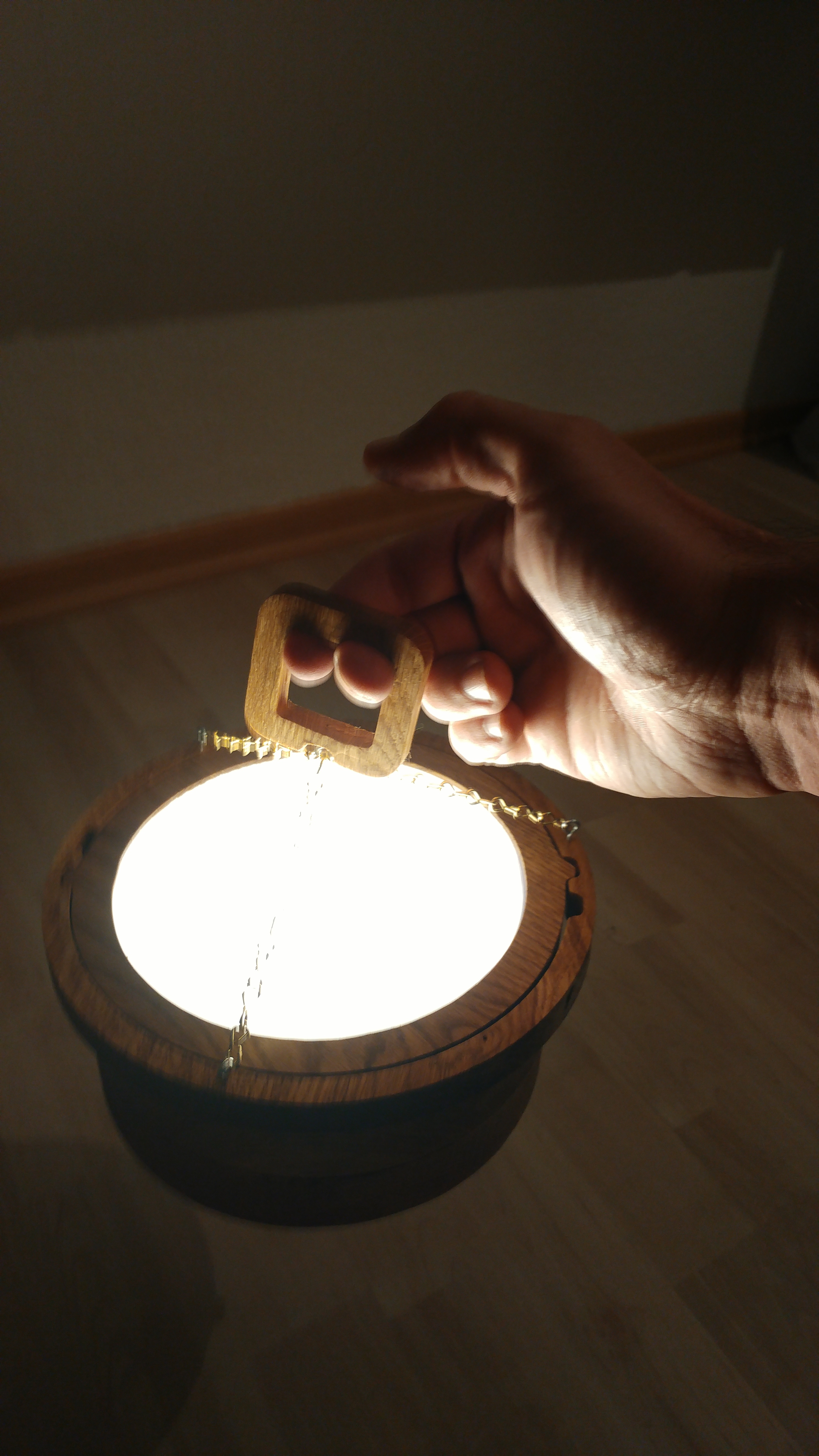
There is this Philips Hue Go lamp… 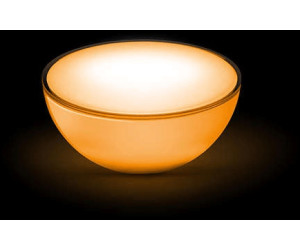
… which I find nice to wake me up in the morning, but otherwise I find its feasibility somewhat limited. That’s because you put it on the floor/table/whatever and it lights from the bottom up, blinding you or not effectively lighting the room.
So thanks to this challenge I came up with the idea to extend its field of use:
Final product
Use it as a down-facing lamp
Use it as an up-facing lamp
Use it as a lantern (up- and down-facing)
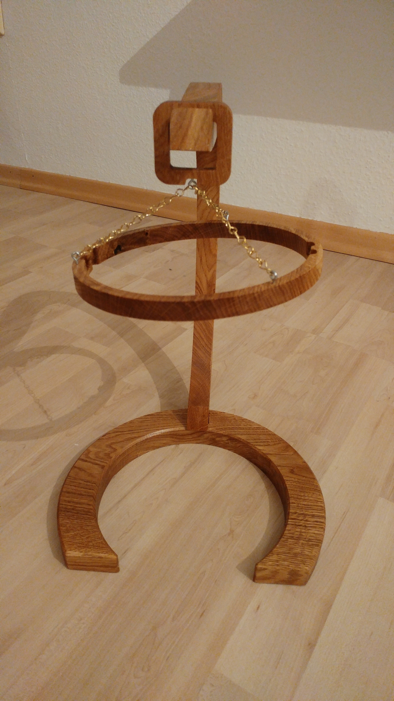
The stand without the actual lamp looks like this:
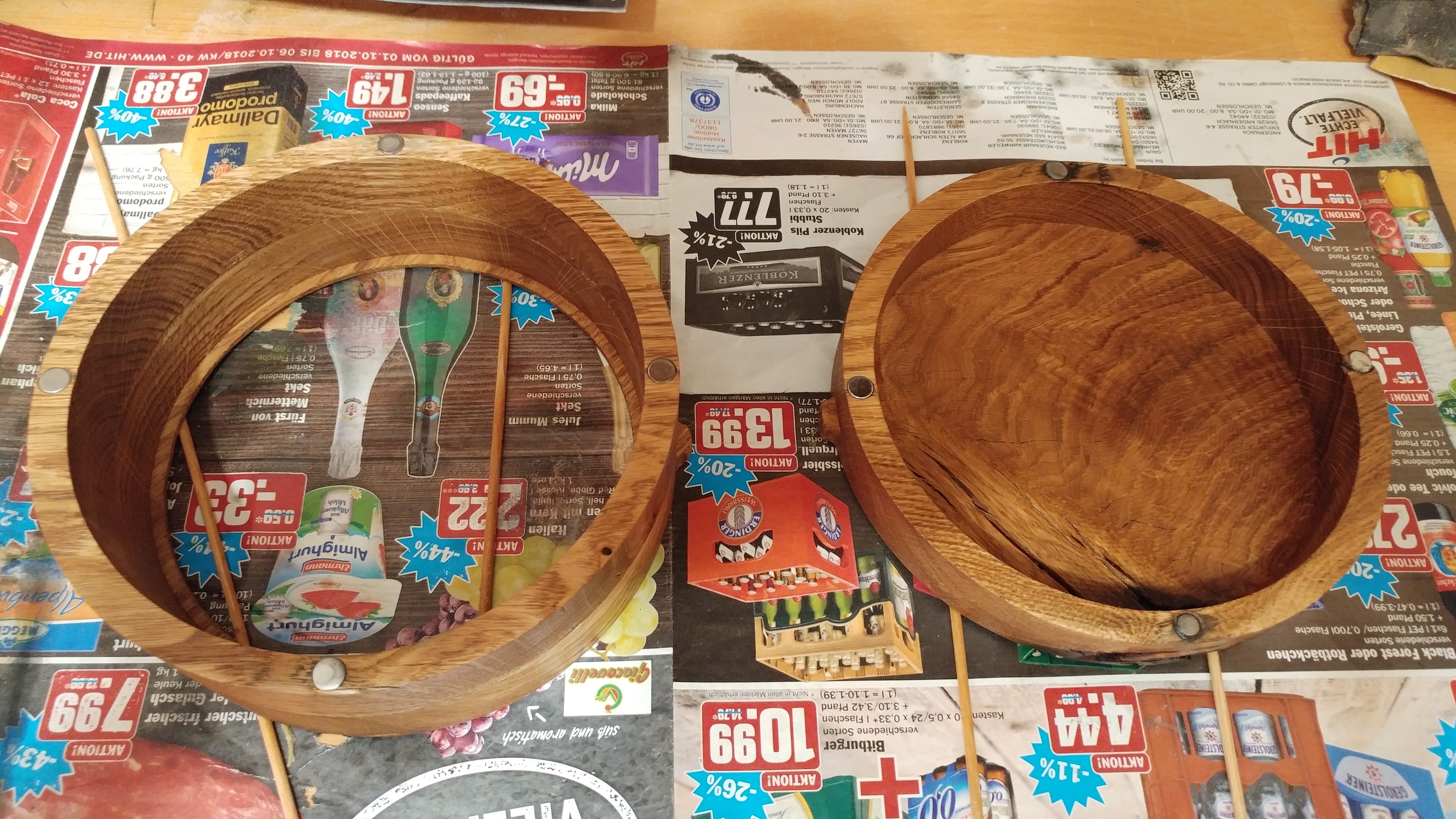
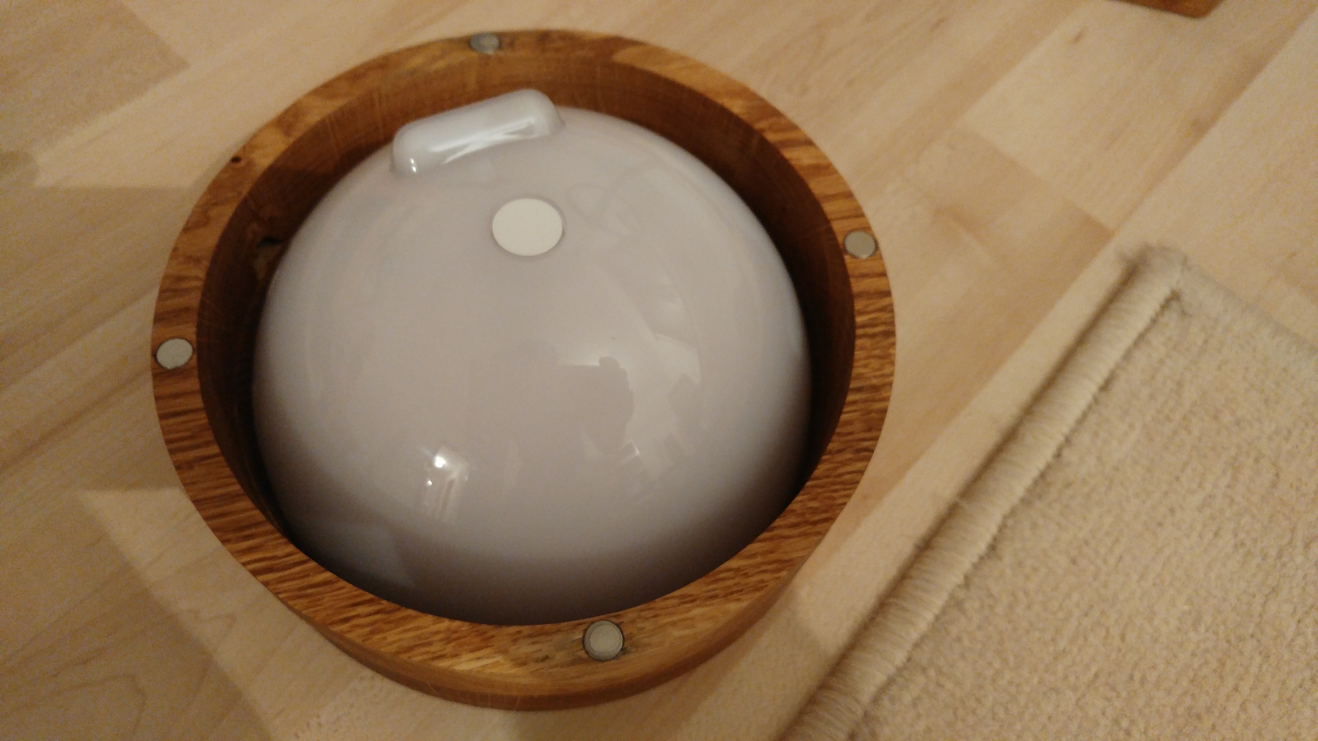
You then put the Hue Go into either of the cylinder parts (
which can be assembled via magnets)
So far the Hue Go can be used with its battery only. I’ll have to figure a discreet way to attach the power supply.
Process
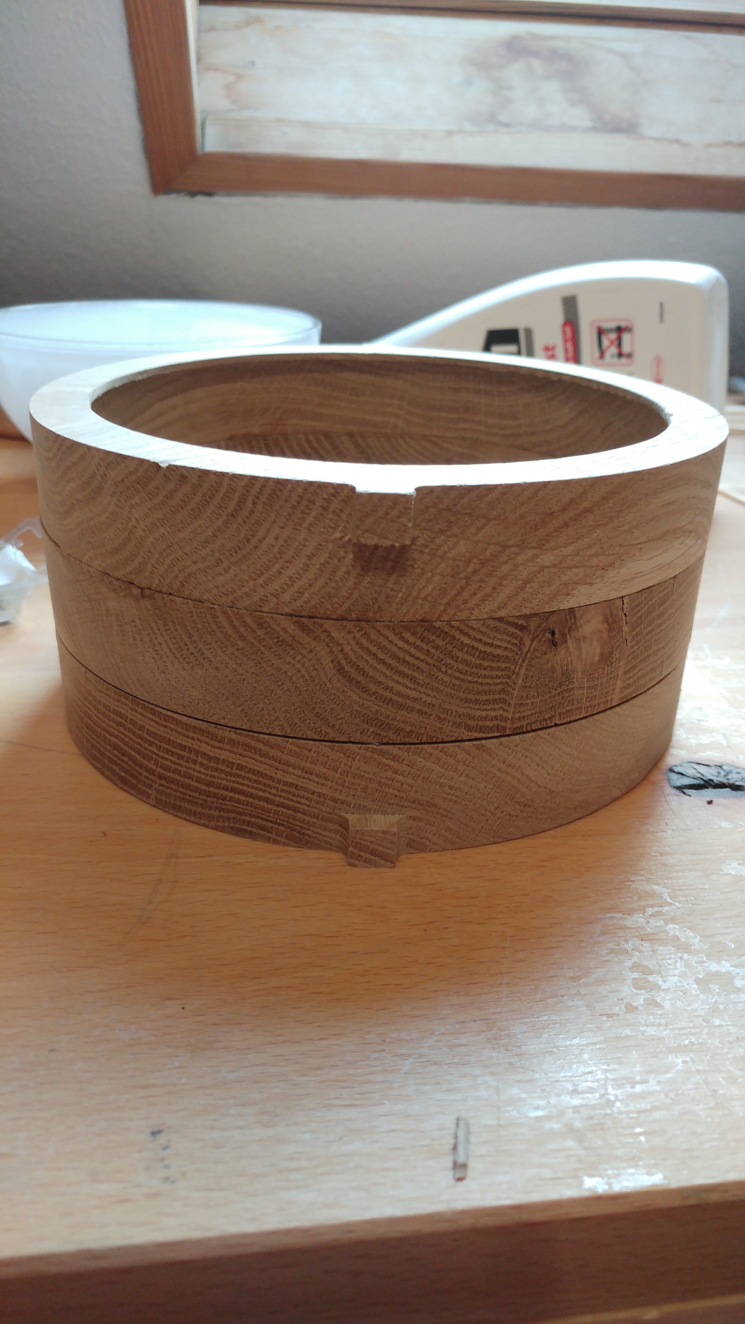
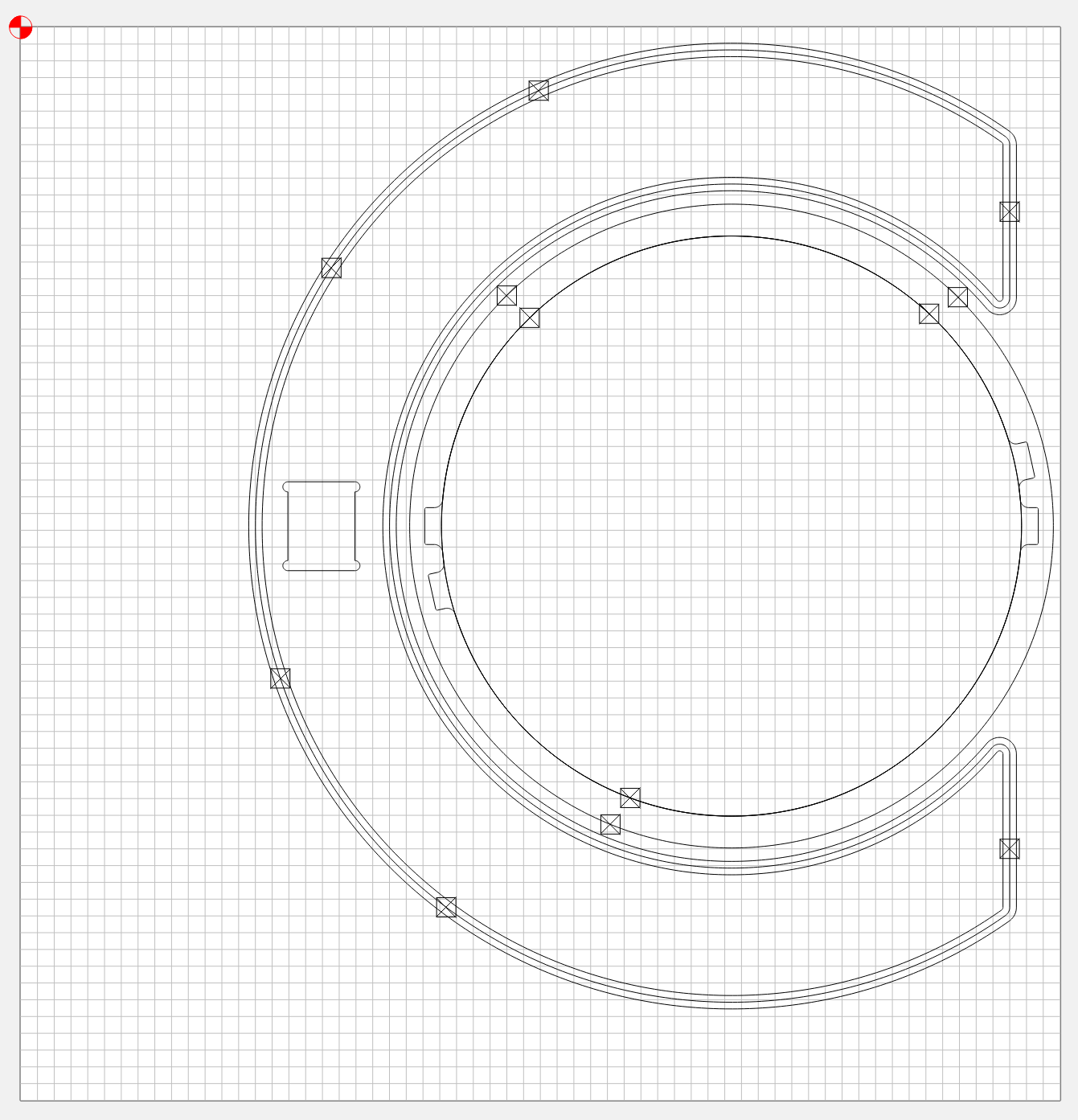
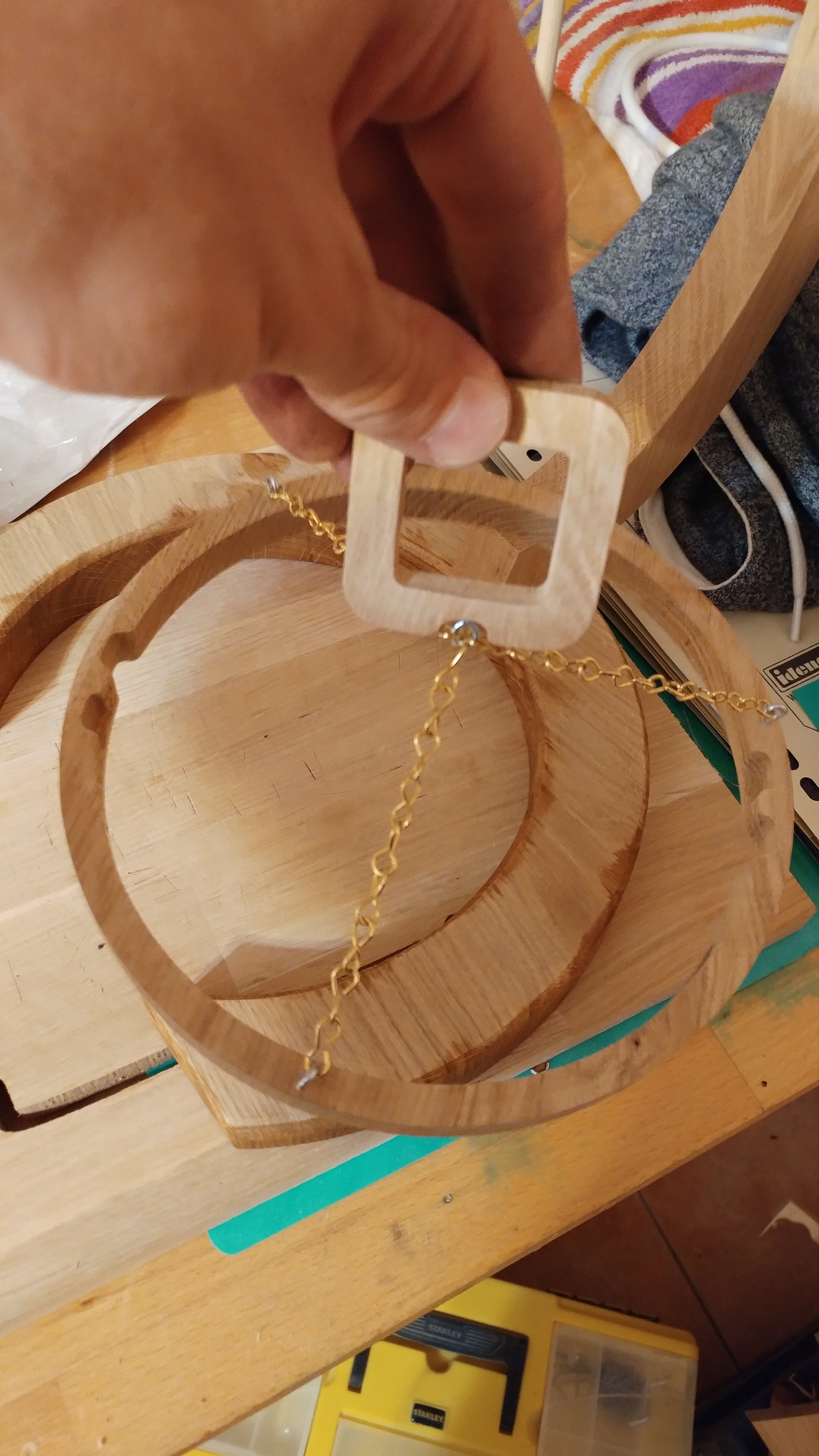
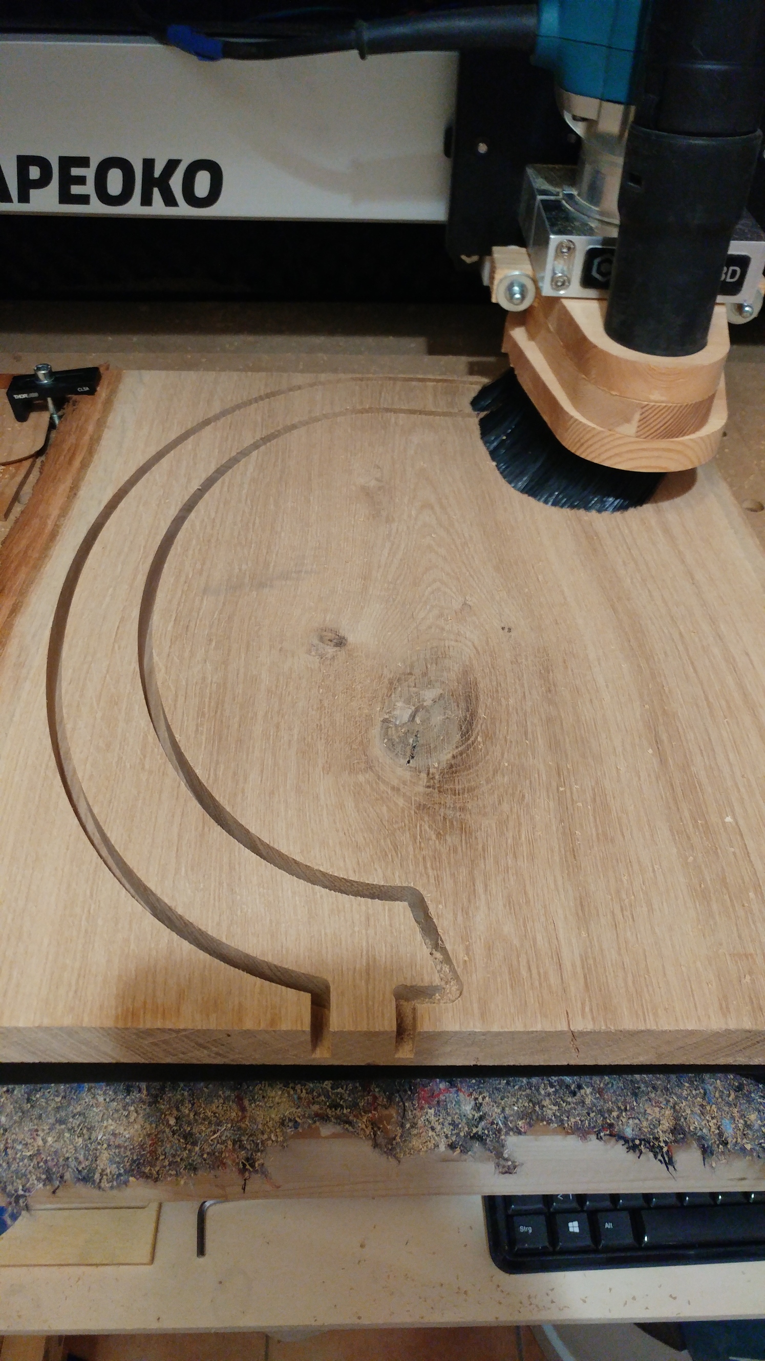
The cylinder where the lamp goes in is assembled from three rings:
The foot of the lamp has a C-shape and here you see the additional ring where the cylinder can snap into.
Finally there is the arm of the lamp and a small piece that helps to hang the cylinder onto the arm.
Everything was cut from 26.5mm oak with a 6mm end-mill. Only the pocket in the foot part was cut with a 3mm end-mill and the foot got a 90°-v-carved edge.
The fitting of the arm and the foot did have a little too much play, even though I designed the fitting parts with no extra space. What’s you guys’ approach when designing parts that should fit tight? I wouldn’t deny the possibility that my machine’s steps are not properly calibrated 
Magnets
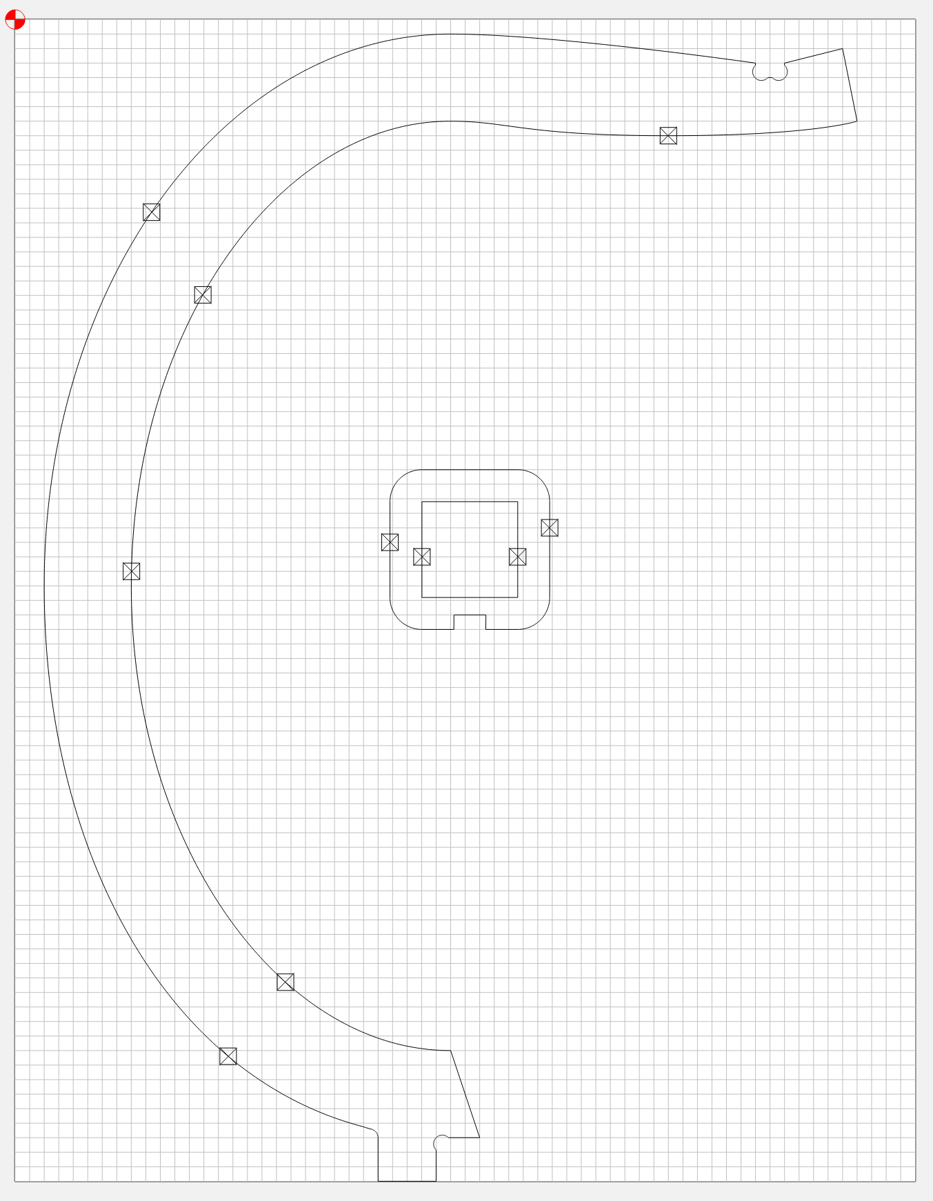
arm.c2d (382.1 KB) cylinder.c2d (1.7 MB) foot.c2d (1.7 MB)
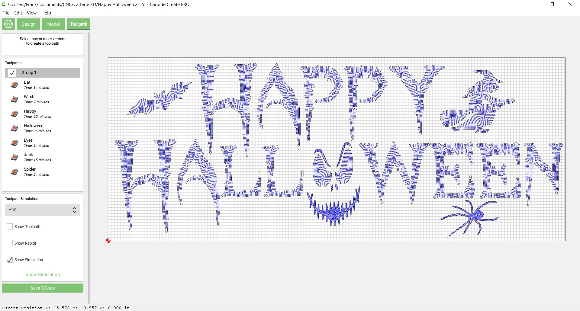
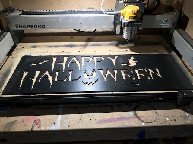
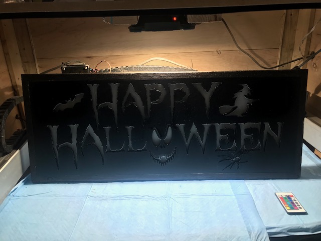
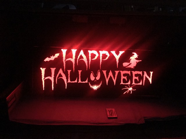
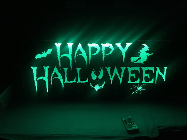
Halloween Yard Lamp !
Pretty simple design for our Daughter. She does serious Halloween Yard Art.
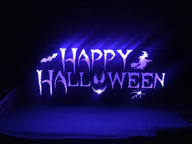
Designed it all in Carbide Create and used Carbide Motion to cut.
Started off with basic black plastic sheet, 1/4 inch thick
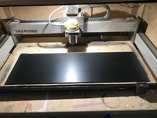
This stuff is a mess to cut !!! Time to buy a vacuum system.
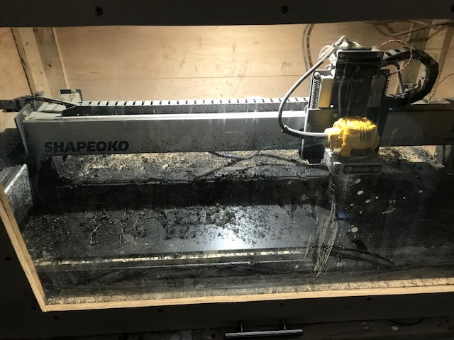
But using pocket cuts with as small as 1/16th in, got some good details and sharp edges.
Prepped the back with blue tape and filled in the sign with clear resin.
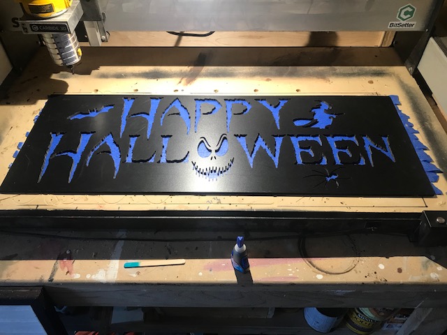
Built a simple plywood box and routed out 1X pine strips to let the sign sit in a recessed frame.
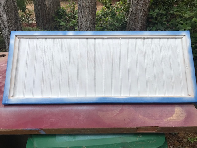
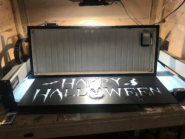
Final Assembly after a dark walnut stain on the outside
Set multi-colored led lights around the inside edge and button magnets in each corner to hold snug in the frame. Can’t upload a movie so here is a small sample:
Design and cut files
Happy Halloween 2.c2d (1.3 MB) Halloween Sign.nc (1.6 MB)
and Cutrocket page
Be safe out there everyone!
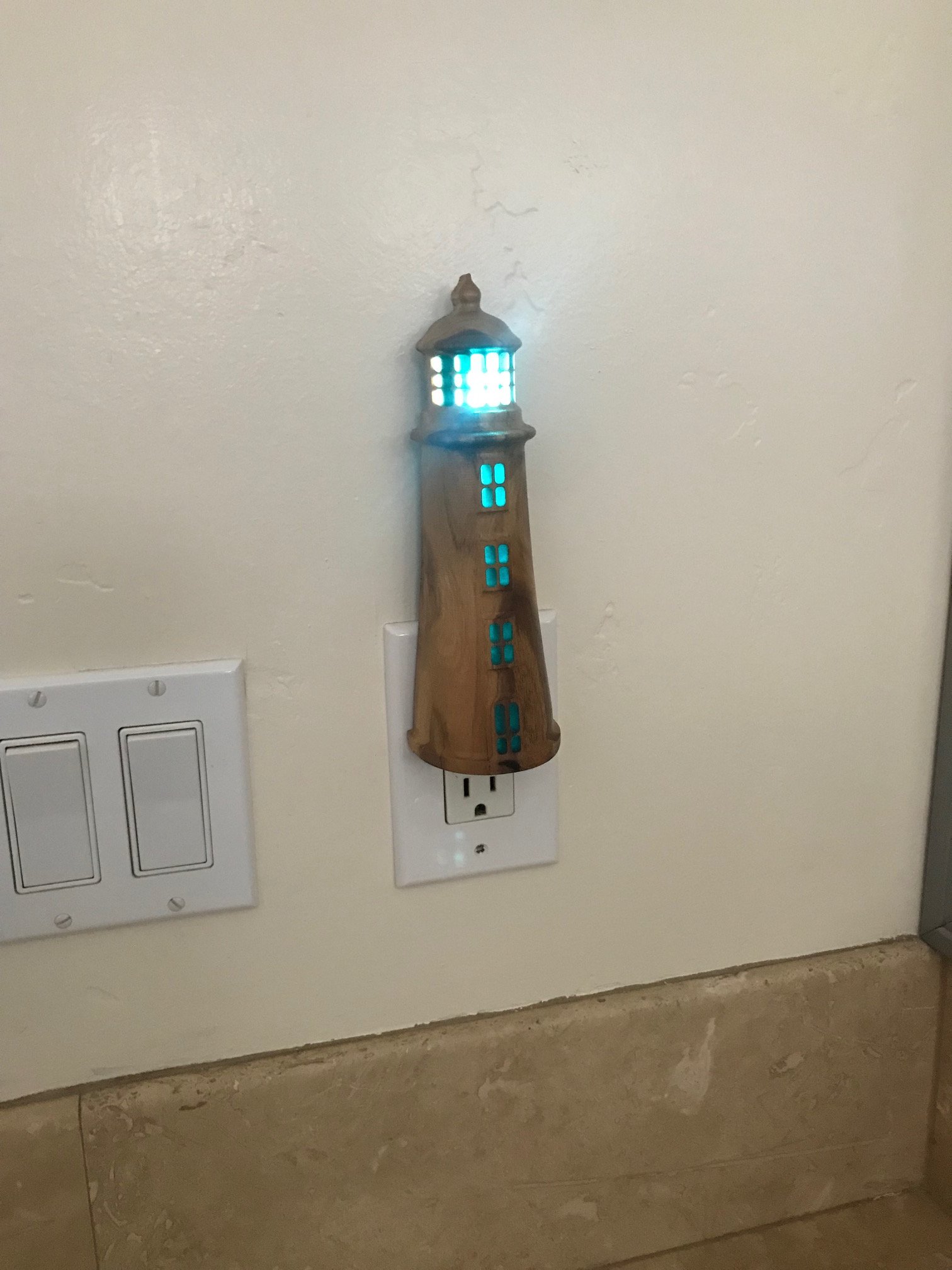
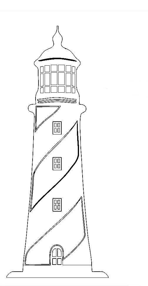
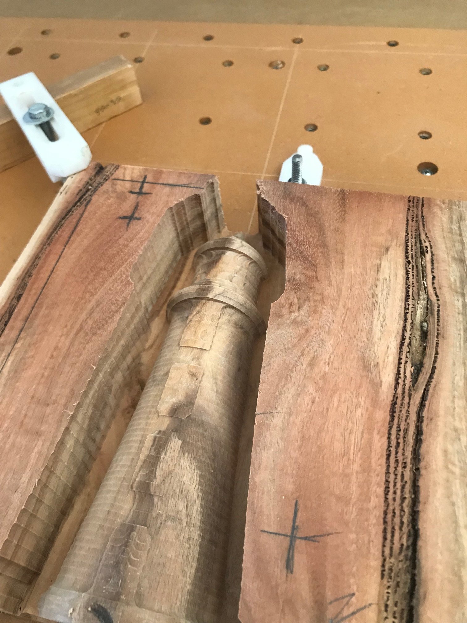
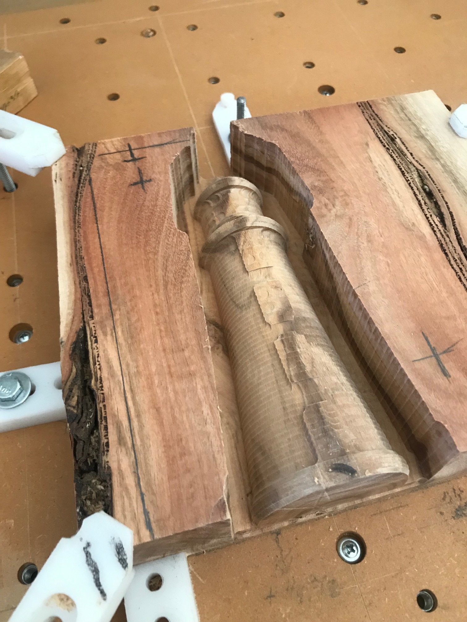
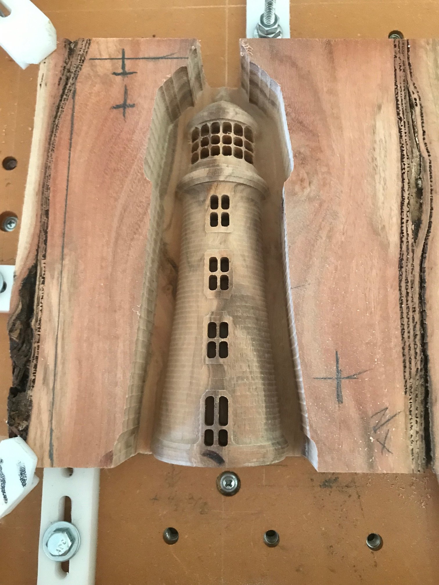
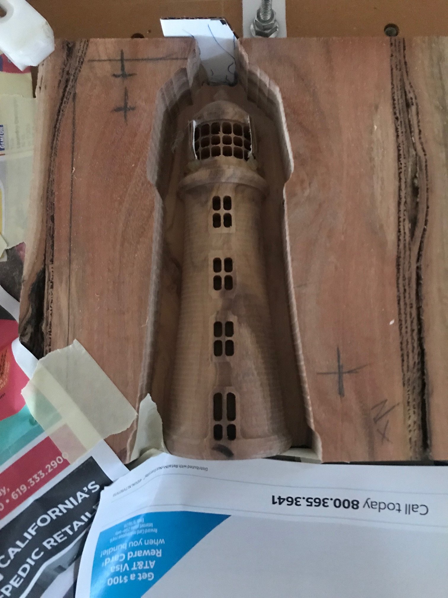
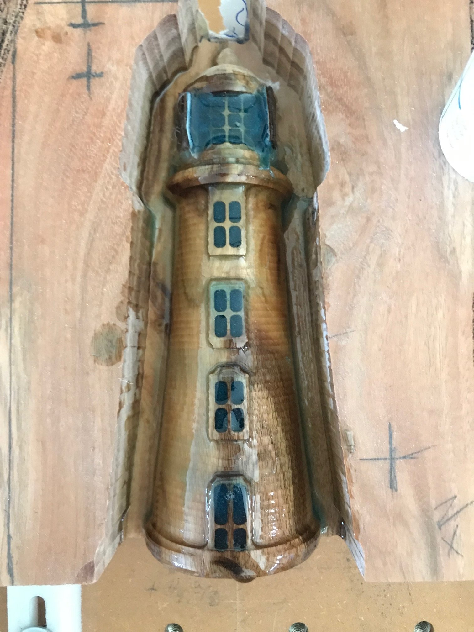
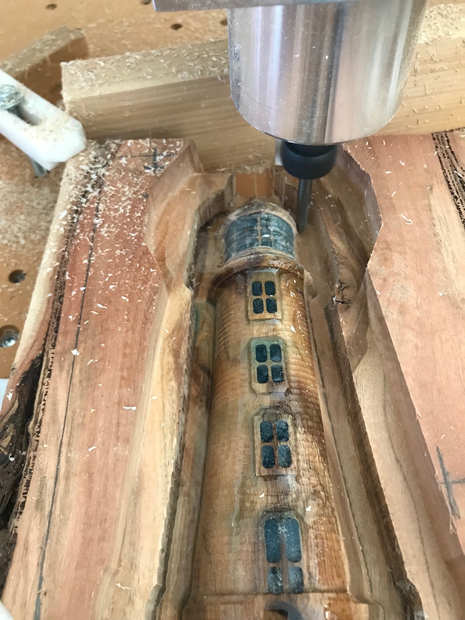
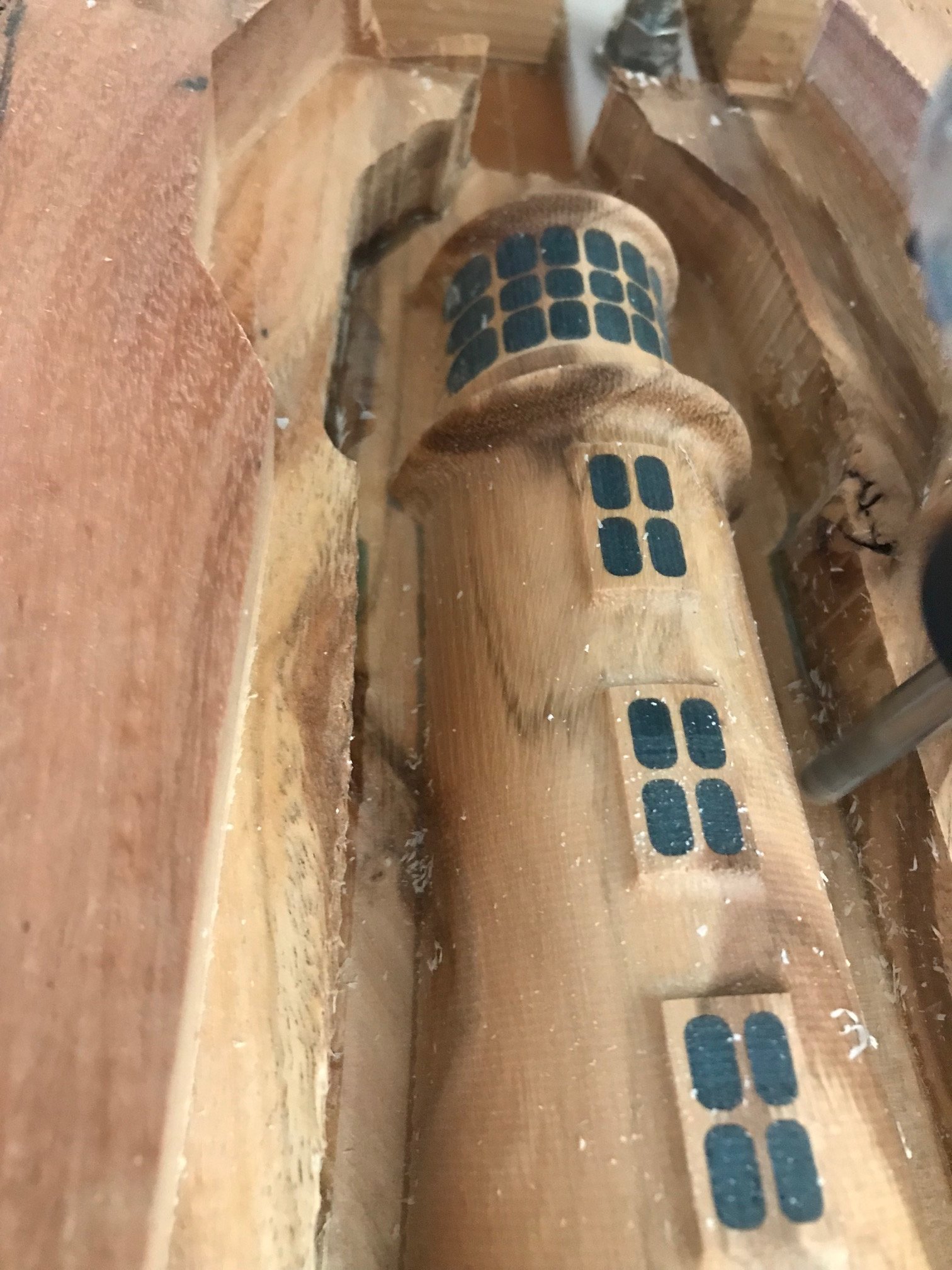
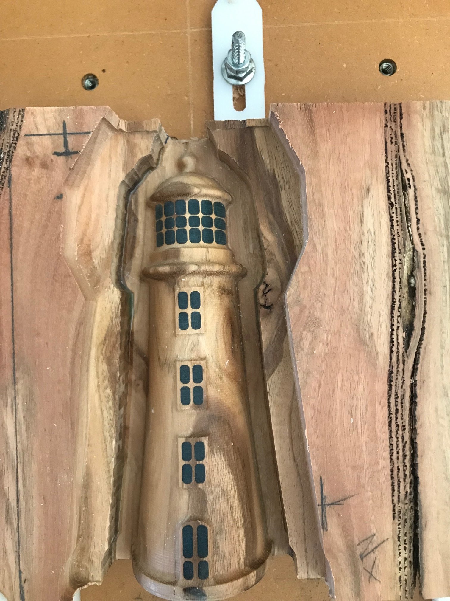
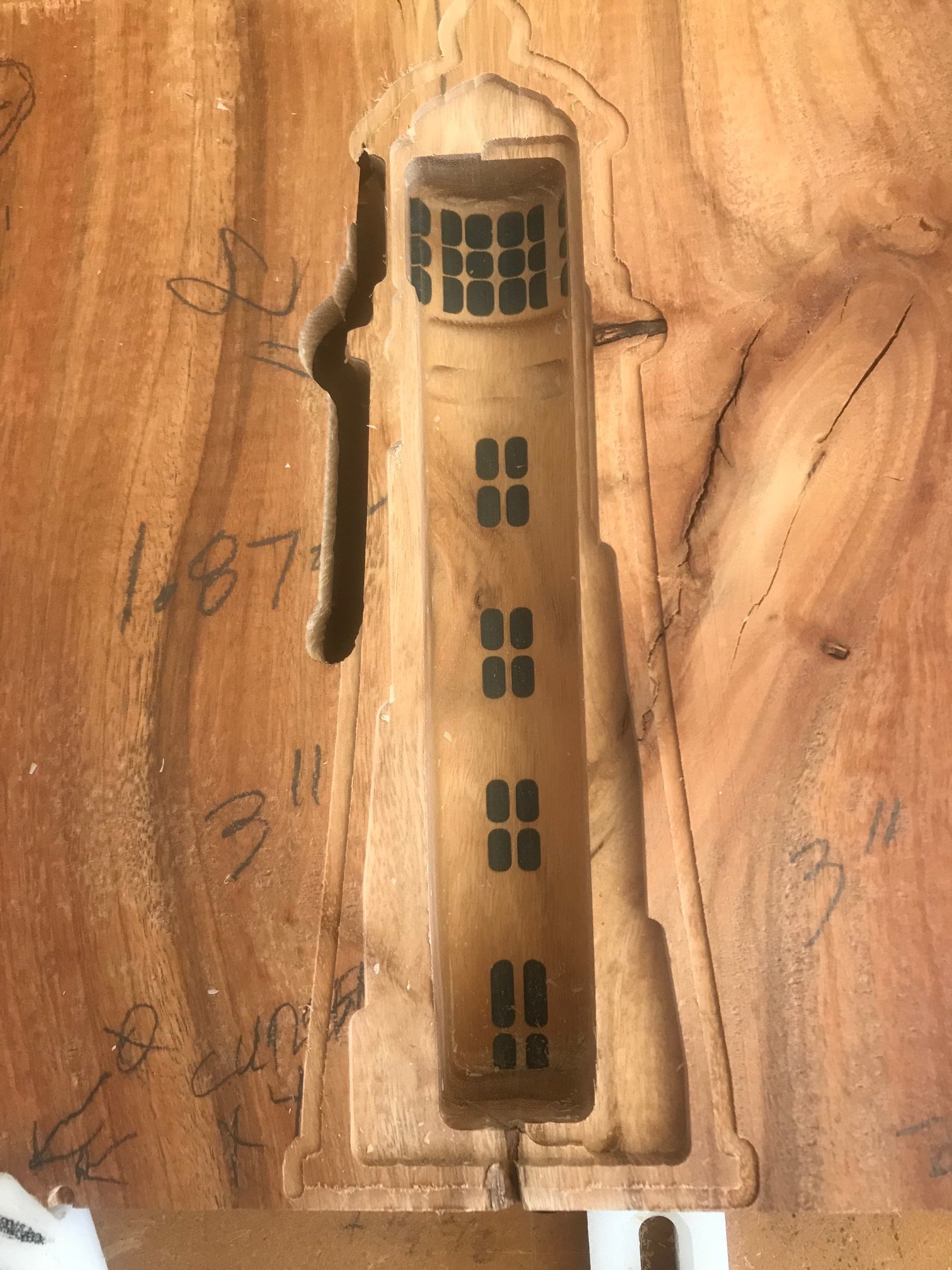
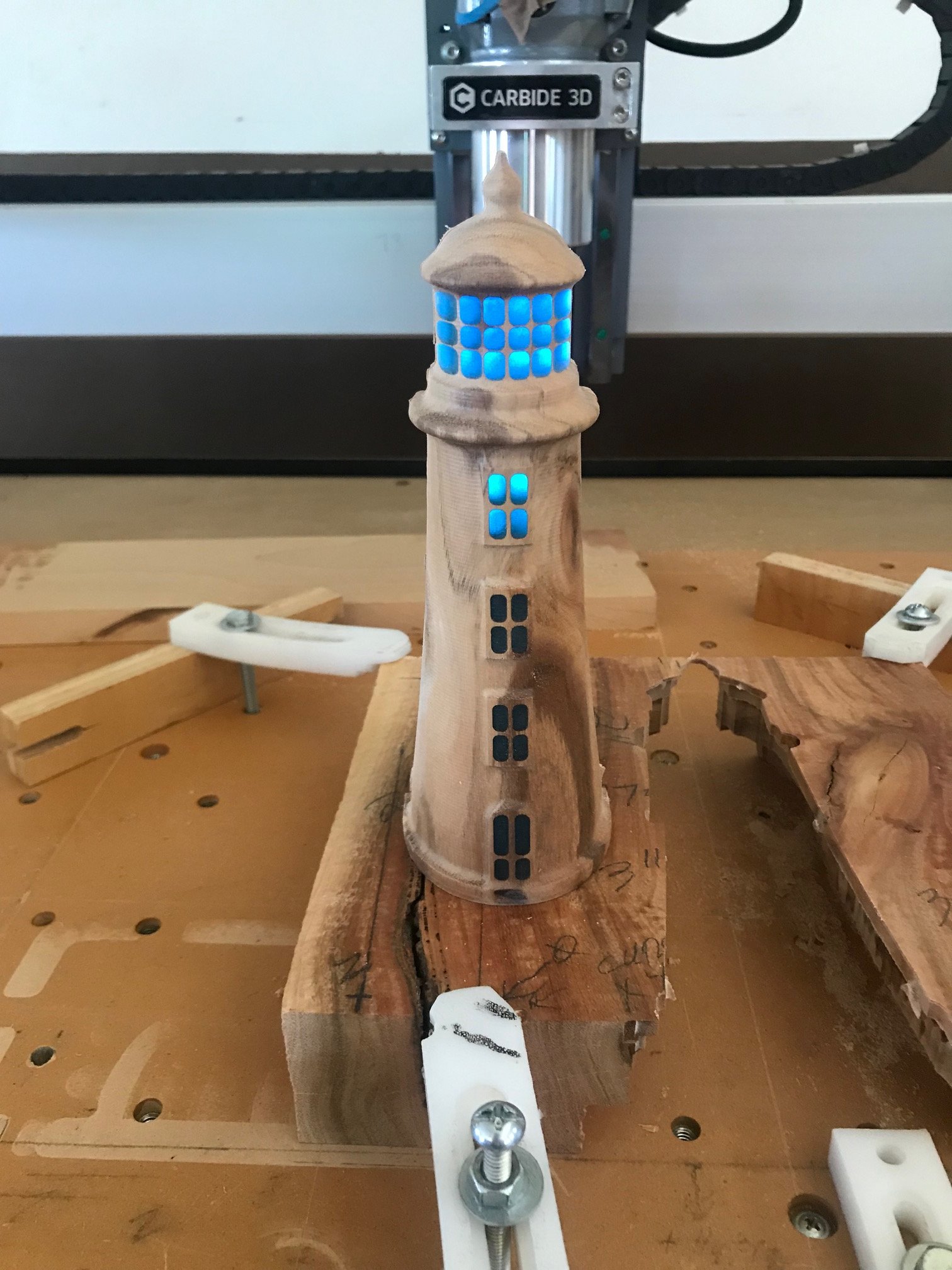
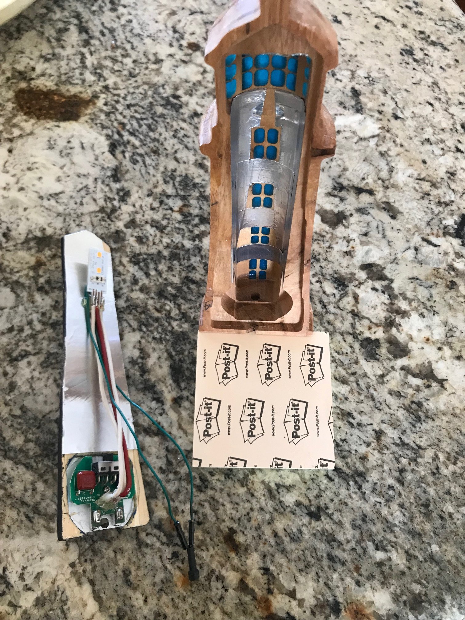
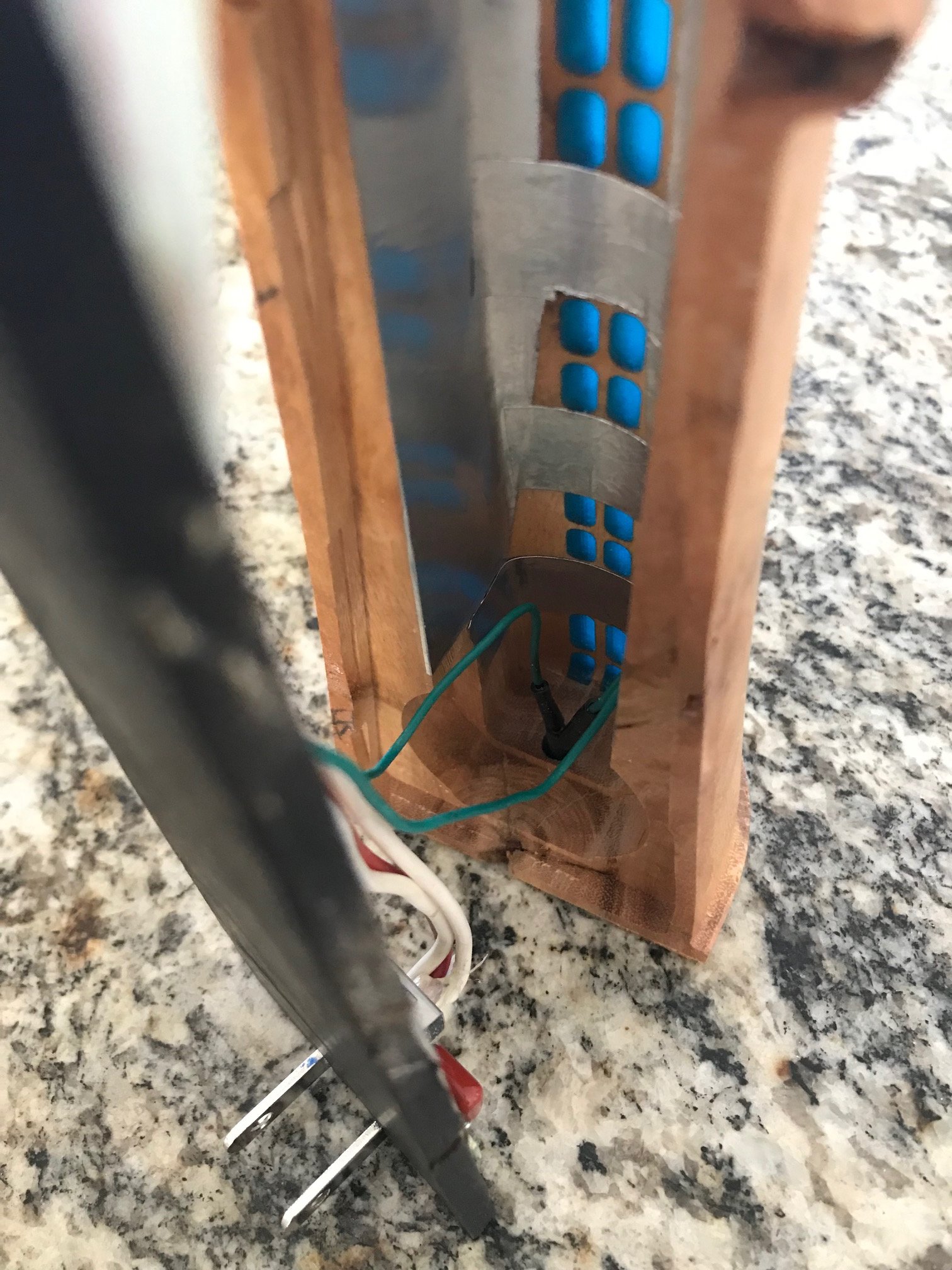
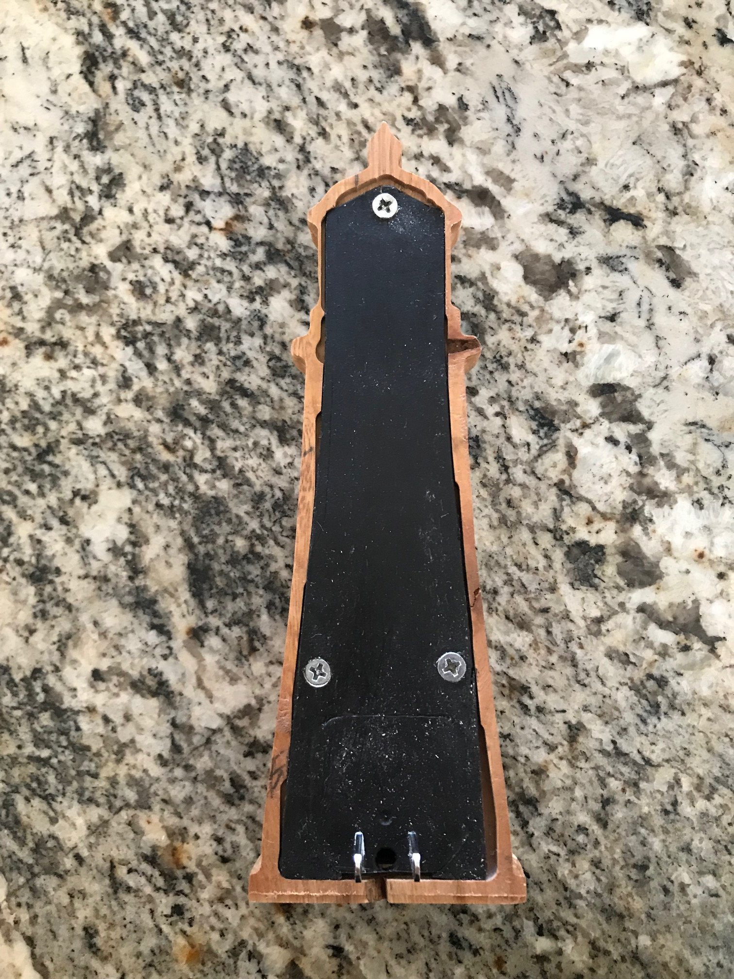
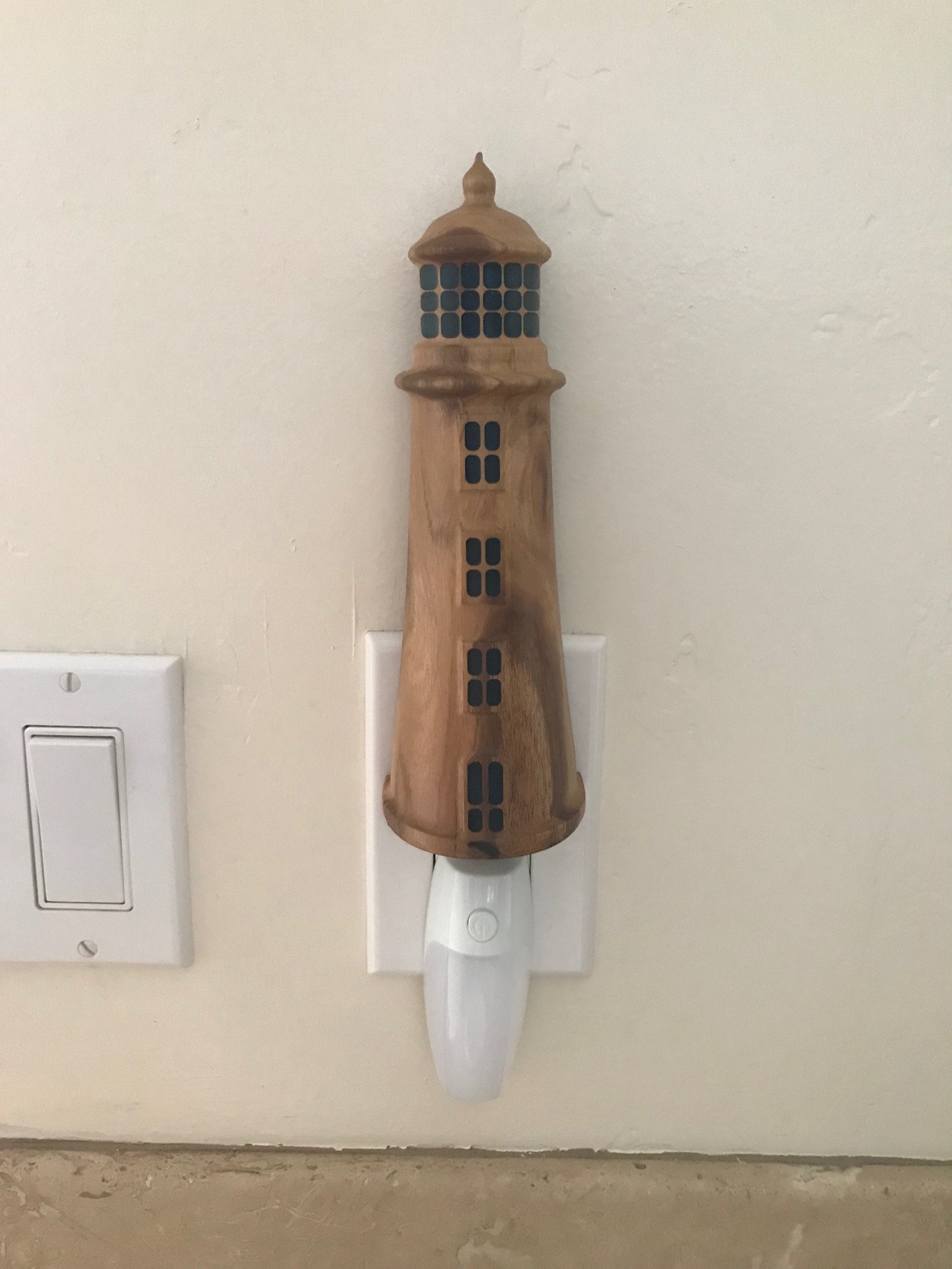
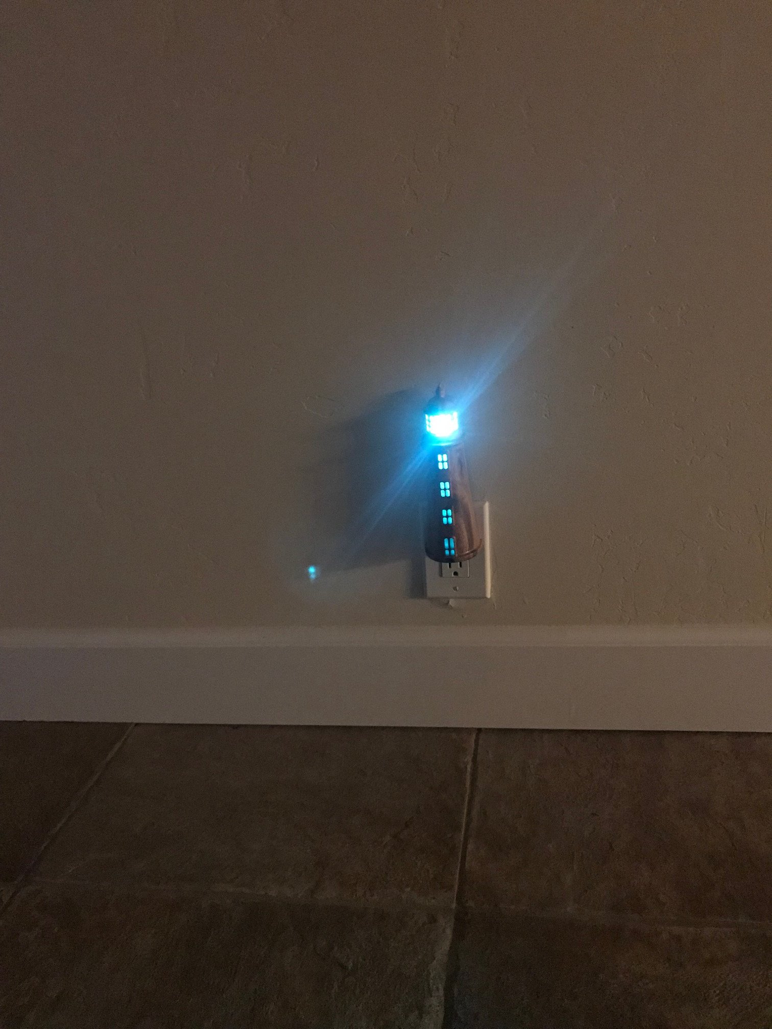
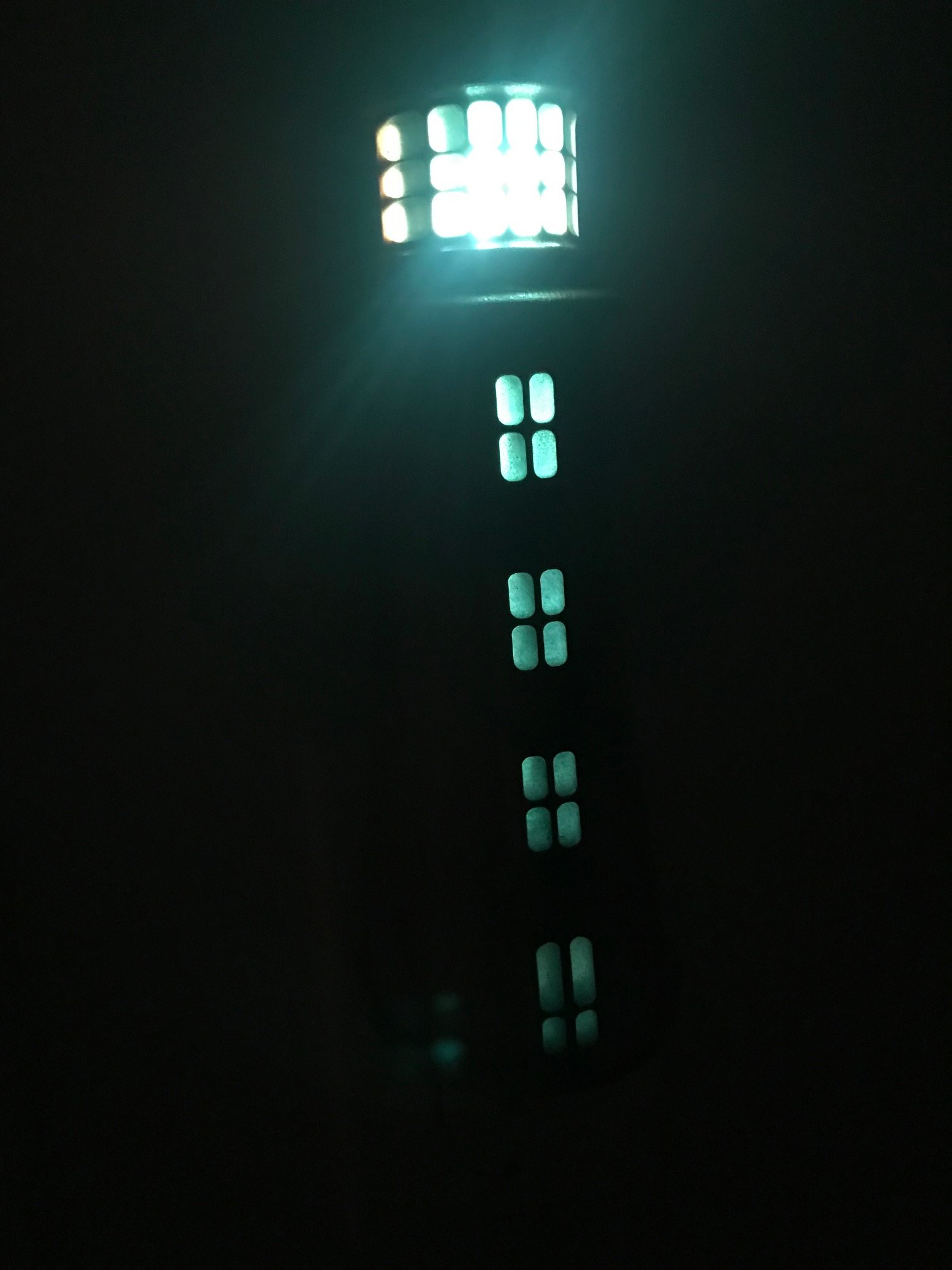
I’ve been wanting to make a lighthouse nightlight for some time now. Thanks to the motivation of Carbide 3D and @Julien, I’ve finally managed it!
I designed and generated all of the toolpaths with Vectric Aspire. Just haven’t gotten a handle on Carbide Create Pro or Fusion 360, yet. All of the cutting was done with Carbide Motion This is my artwork, so all are welcome to use as they see fit.
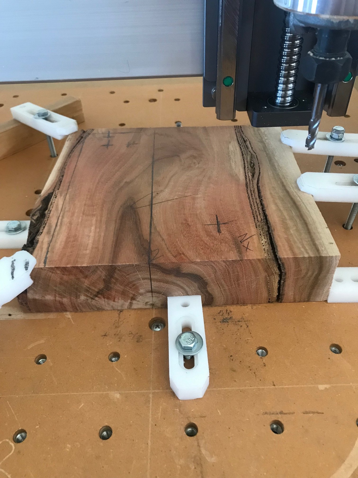
Here’s the block of wood (eucalyptus) ready for the first 3D roughing cut:
Incredible result. That wood is freaking gorgeous and goes so well with the epoxy. The lighthouse is also so fitting for the purpose!
Had to chuckle at your reference to “the checklist” when the bit slipped. I’ve had moments like that where I’m just so perplexed as to how I could forget something like that, but in the hurry and excitement to get rocking, I hand tightened the bit, got right to zeroing or hold down work, final file changes… then ready, set, fail! Glad it wasn’t catastrophic and amazing result!