Neat! I like the highly specific pocket in the middle 
don’t forget to upload your design file to validate your entry (and upload it on CutRocket for bonus points too)
I also have a surfacing bit that suffers from this problem, I have to loosen the set-screw on the bitsetter and slide it over to catch the edge of the bit. So I am very interested in your solution.
I’m assuming the thichness of the part has to be perfect, to thick and the tool appears shorter, too thin and the tool appears longer… or is there some voodoo happening here that I don’t understand (regarding the tool measurement)?
The specific thickness isn’t crucial, because it’s a relative adjustment from the initial probe on startup. You just have to make sure the top is flat/planar.
I’m afraid this won’t do, as one of the rules is to provide the design file for entries.
Belts, tensions and improvements
Somehow I managed to damage one of my Y belts, so got a roll of steel core GT2 9mm replacement and read up on belt tensioning techniques. During this, and whilst it may be only a minor hassle, the process of creeping the belt one tooth more or less in the clamps, holding it all still whilst tightening the lock screw bugged me.
I saw various others had been similarly bugged, so the task was born… Adjustable belt clamps
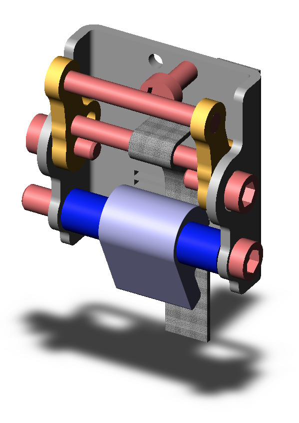
After exploring and sharing various ideas, and enjoying the banter and humour that accompanied it, I settled on a design. I worked up the rotational geometry first, then designed the parts in CC (and copied them into VC too).
The requirements were:
- Avoid modifying the 3XL where at all possible
- First ‘threading’ of the belt should be fuss-free
- Screw adjustment of the final belt tension
- Be unaffected by vibration and debris during operation
- Be made on the 3XL
- Ideally not turn a whole block of Aluminium into chips - so cutting then bending sheet stock
- Cater for 9mm and 15mm belts if possible
- The same part for left or right Y fitment, and for X left or right too
But first, I had to take the plunge and cut some aluminium and find out feeds, speeds and clamping that works for me - with the standard Z and Dewalt spindle. Tests run, chips made, noises understood. Now I know I won’t wreck things.
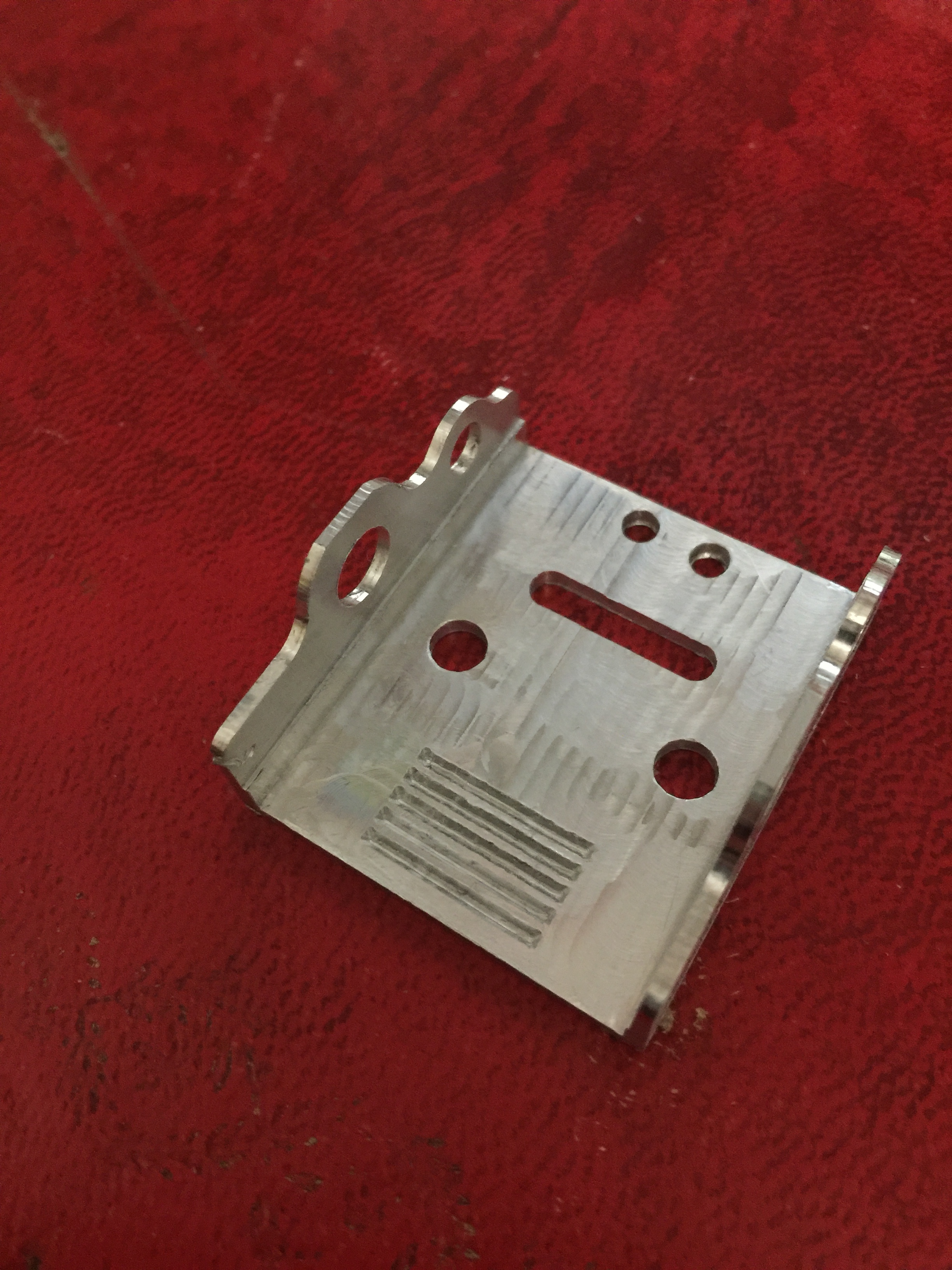
Bought some sheets of 6061 Aluminium, 2mm thick and set about cutting out the profiles (CC files attached, and Vectrics too).
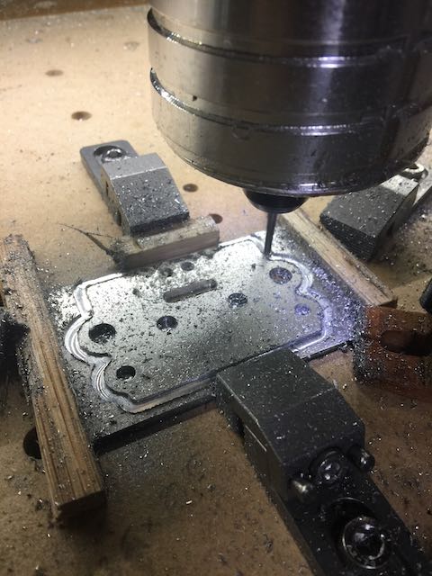
Reading up on Aluminium grades, after snapping a piece whilst test bending, it turns out that 3000 grade might have been easier to work with - however, annealing is also effective on 6061. Using the ‘candle soot’ temperature test (fascinating topic of its own) to hit annealing temperature, then folding the parts using a vice-mounded vee-bender (bought from Warco Tool Supplies in the UK). Happy with the results, given the bend radius achievable wasn’t quite as tight as I ideally wanted. Stainless Steel 1.5mm could have been much tighter, but baby steps…
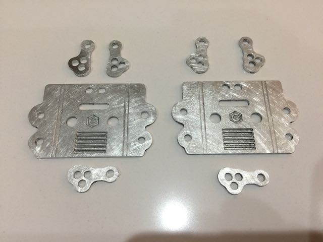
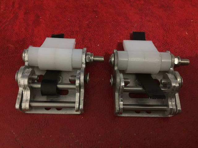
The small ‘arms’ are the adjustment mechanism - more on that later.
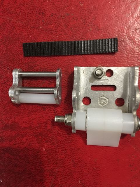
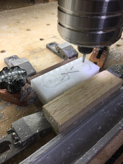
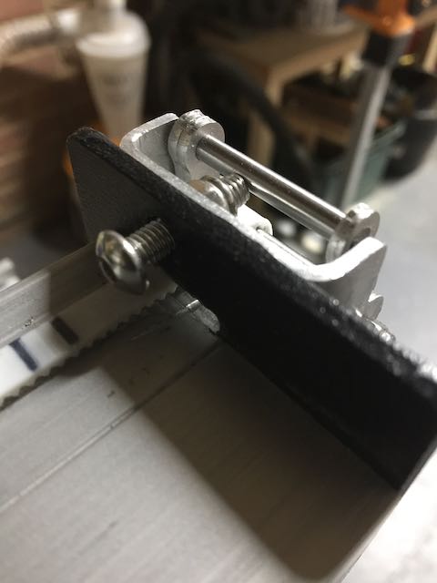
The initial threading and clamping of the belt is acheived with an eccentric cam above ‘teeth’ (2mm spaced, 1.2mm/60-deg vee carved grooves 1mm deep in the clamp body) this profile quite closely matches the profile of the GT2 teeth and was simple to cut on the 3XL. The cams were cut from a sheet of HDPE, two layers bonded together with Locitite Ionic Activated Cyanoacrylate adhesive (£6 on Amazon), to achieve 20mm thickness.
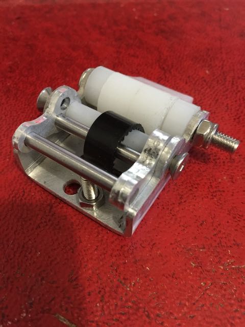
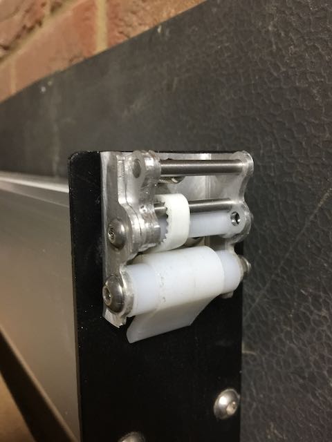
The arms are assembled by press-fitting two 4mm ground steel pins, one being the actuator that the adjustment screw pushes against, the other forming an eccentric diameter as the arms rotate, pulling more of the belt through the slot from the 3XL and thus tensioning it. I added a spare pin position just in case I wanted to adjust things later on.
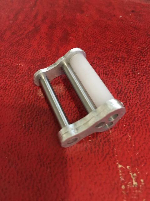
The clamps are simply assembled with 2 cap-head screws to hold the adjuster and eccentric cam in place. The pics show overly long screws, but will fit correct length screws before final mounding on the 3XL. A little adjustment of the cam profile was necessary as hand bending the aluminium didn’t give a precise wall ‘height’ which the cam is dependent upon.
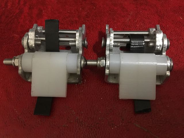
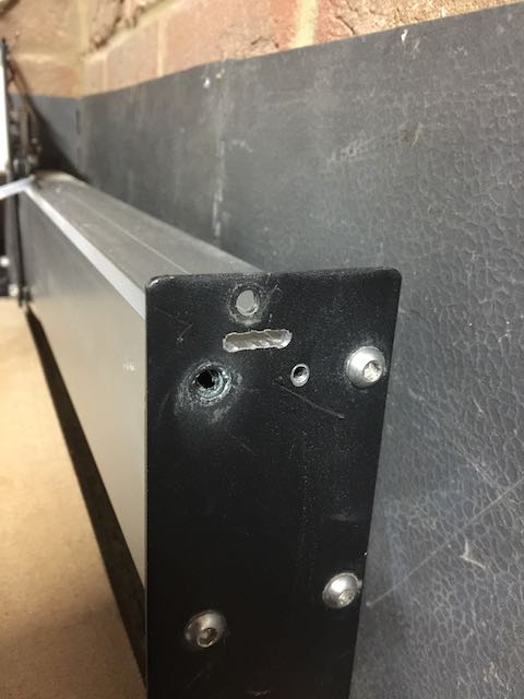
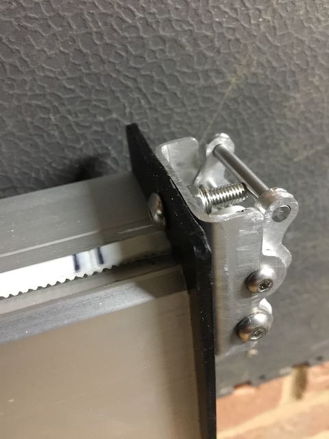
The 3XL frame has to be slotted to allow the belt to pass through, so I drilled and filed a 4mm x 16mm slot taking care not to damage the extrusion surface. My arms look like Popeye’s now, but the result is worth the effort (and sweat). This is the only mod necessary to the 3XL and won’t affect rigidity at all.
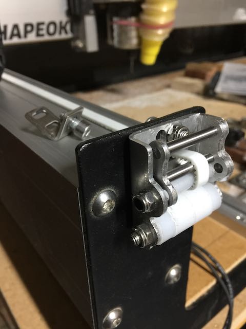
Mounting the clamp now only requires removal of one plate/extrusion screw, and the original tensioner screw, then re-using the plate screw to hold this new clamp in place. Pass the tail of the belt through the slot, over the top of the new adjuster arm, and under the eccentric clamp. Pull the belt tight by hand and close the eccentric ‘snail-cam’ clamp. With a longer screw passing through the original adjuster screw hole in the 3XL chassis, tension the belt with it as it pushes the adjuster arm open. Use your preferred method (pencil, ping or sound test) to achieve the right tension and ensure the adjuster screw lock-nut is tight.
I know the holding force of the snail cam is good, I couldn’t move the belts when pulling on a scrap piece with pliers - the GT2 belts are designed to hold by tooth to groove lateral contact, not from compression force. The concern over vibration loosening the adjuster arm was overcome in the final design by using a locked-off screw to move the arm. I did for the final assembly of the clamps add a HDPE sleeve over the arm pivot screw to avoid thread contact damage.
Just finishing off some Christmas promises on the 3XL (inlays and trivets from Bamboo - must have caught @Julien’s bug for these…), then I will finally fit and show these clamps in situ. I can’t wait as overcoming the original ‘fiddly clamp bug’ has resulted in these quite-nifty parts.
What a fantastic machine. And a fantastic forum community too - the initial ideas were critiqued and from that I could make improvements. If you fancy making some, would be happy to share the trials and tribulations as I experienced them - either way the geometry and action works however you choose to actually fabricate the parts. And who knows, someone at Carbide 3D might be watching with interest too for a future product enhancement  Would be my gift if adopted.
Files for Carbide Create and Vectrics VCarve attached and on Cut-Rocket.
Belt Tensioner Clamp Flat Profile Rev-2.c2d (238.8 KB)
Belt Tensioner Snail-Cam Rev-2.c2d (16.6 KB)
Belt Tensioner Snail-Cam Rev-2.c2d.zip (3.1 KB)
Belt Tensioner Clamp Flat Profile Rev-2.crv.zip (357.2 KB)
Edit: Have cut the other belt access slot in the XL frame, fitted and tensioned both Y axis belts. It works!! Tweaked both belts to get the exact same tension ‘ping sound’ (un-scientific, but it proves the principle) by simply a few tweaks on the adjuster screw. Very happy with that. Now to run some of those Christmas promises I still have to finish…
The slot in the frame is the only essential cut. I added a second fixing hole, tapped out to M5 ‘just for comfort’
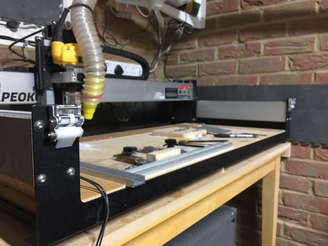
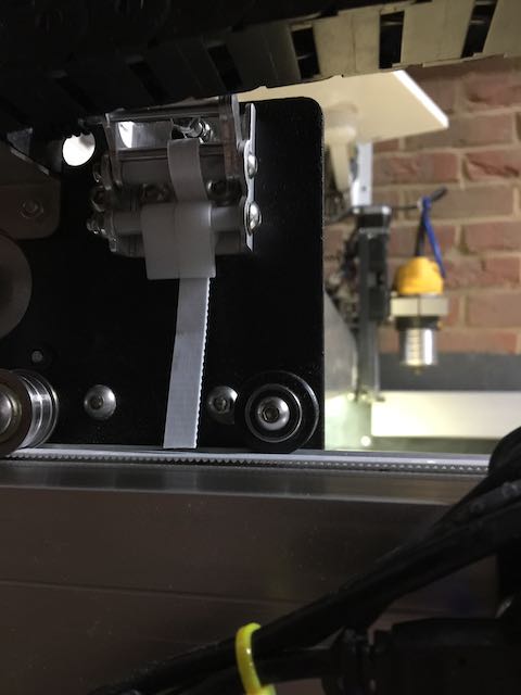
Fitted Left side clamp and initial tighten
Then the right side, deliberately set the tension point further out on the adjuster arm to confirm the range of movement
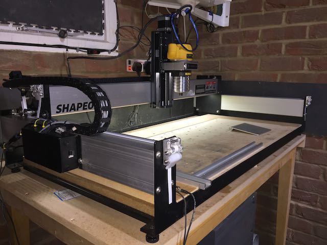
My 3XL ‘pimped’ with very convenient belt adjusters
14 Likes
Can you bolt it to the machine and test it? Would enjoy it if you would explore sharing some photos of it in action 
1 Like
This evening’s remaining task is to trim down several Bamboo inlays, so the machine will get a workout - I have no doubt the tensioners will hold firm, but will be interesting to see.
Then, finally, I can fit my HDZ knowing that all ‘must do’ tasks are finished, and I can afford some tinker time to get the HDZ setup exactly…
2 Likes
-Thanks for uploading the pics, looks pretty nice on there congratulations!
1 Like
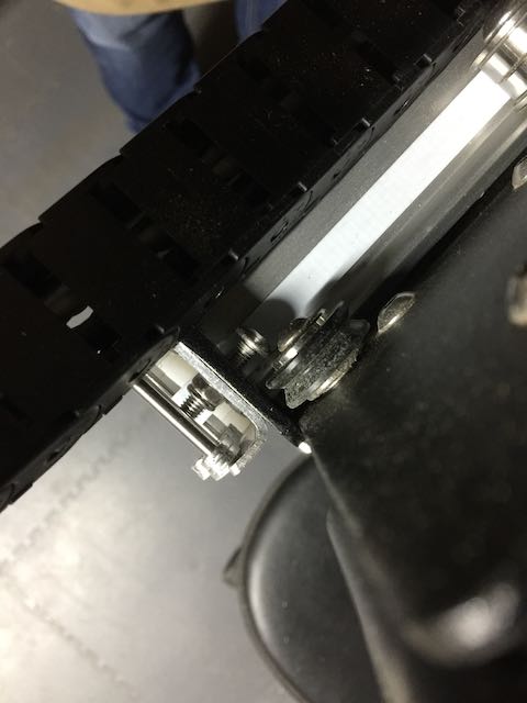
Nice to see the adjuster screw on the belt clamp clears the pulley track. I know it was factored in during design measurements, but nice to see achieved;
Also pulled out the 6mm steel GT2 belts that had been an stop-gap, and fitted the 9mm GT2. Fitting them was a breeze: feed belt through slot, under snail-cam, pull tight by hand, lock, adjust tension with spanner. Done. In the words of Strictly: FAB-U-LOUS
1 Like
Ran a trimming/surfacing cut on an Oak inlay, using my 1" End Mill. The cut was intentionally aggressive, chips (good size chips) flying everywhere, and 30 mins total - and the adjustable belt clamps didn’t shift at all. The exact same ‘ping tone’ on both belts before and after the cut. Happy days!! Now to make the arms for a third clamp and fit it to the X gantry
Third clamp finished and fitted to the Y1 end of the X gantry. Then spent the afternoon installing the impressive HDZ and proximity sensors, and pleased that the new (now dubbed HD Clamps ) belt clamps really simplified the re-fit of the X belt and tensioning. Doubly happy.
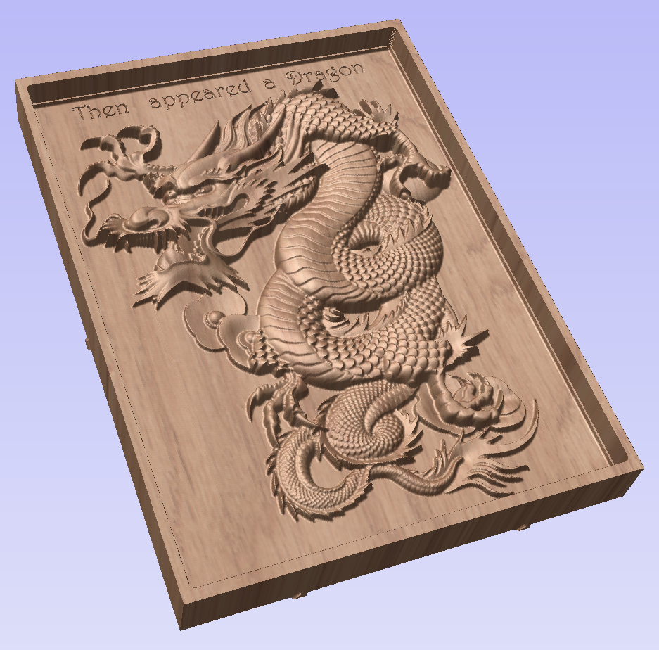
Trammed and ready for a 2,5D carve of a dragon I’ve been pondering.
The Dragon project coming together… Just finishing off wiring and fitting my new 800W spindle, then will run this
2 Likes
Final week-end. Come on, you know we love last minute entries!
1 Like
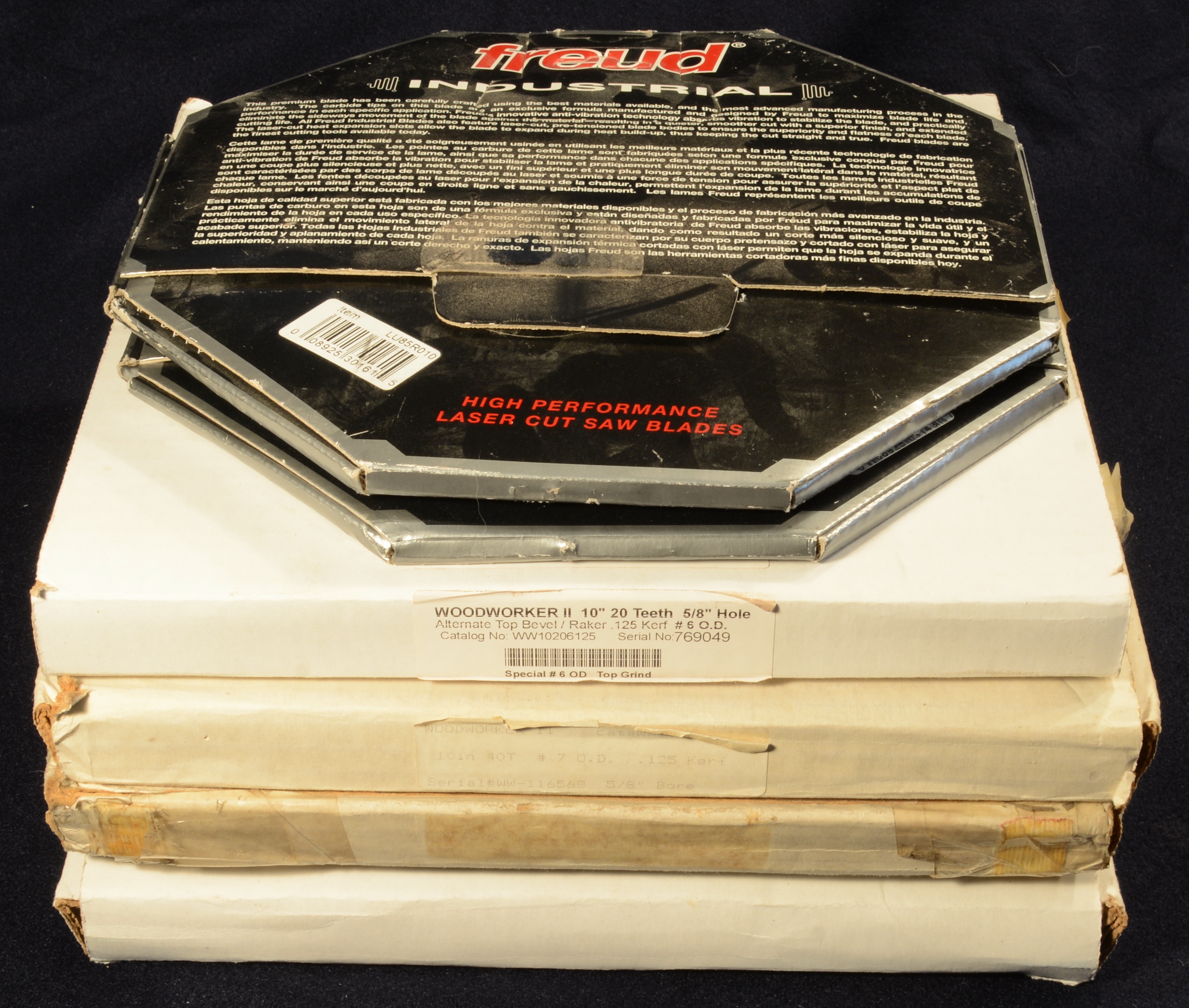
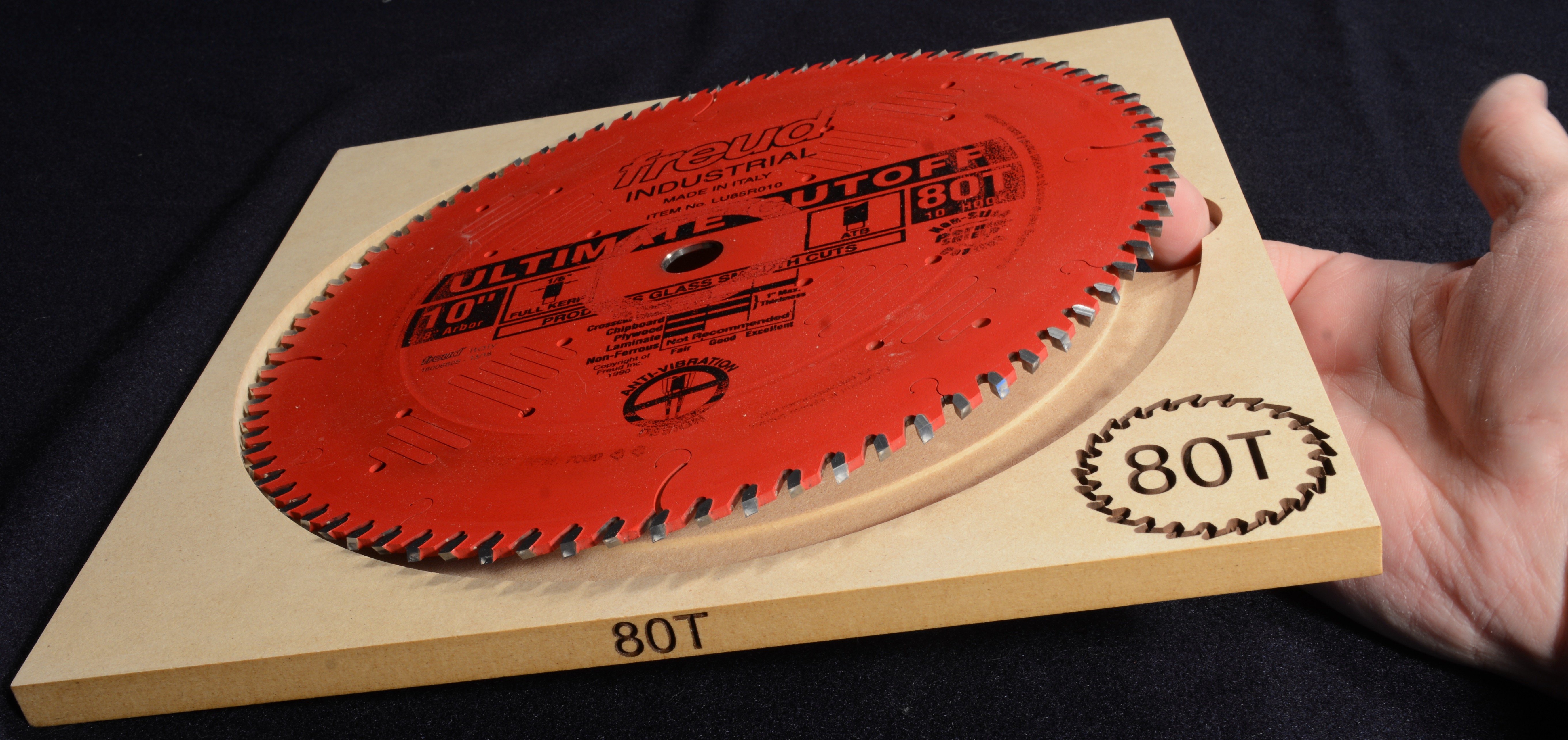
SAW BLADE CADDY
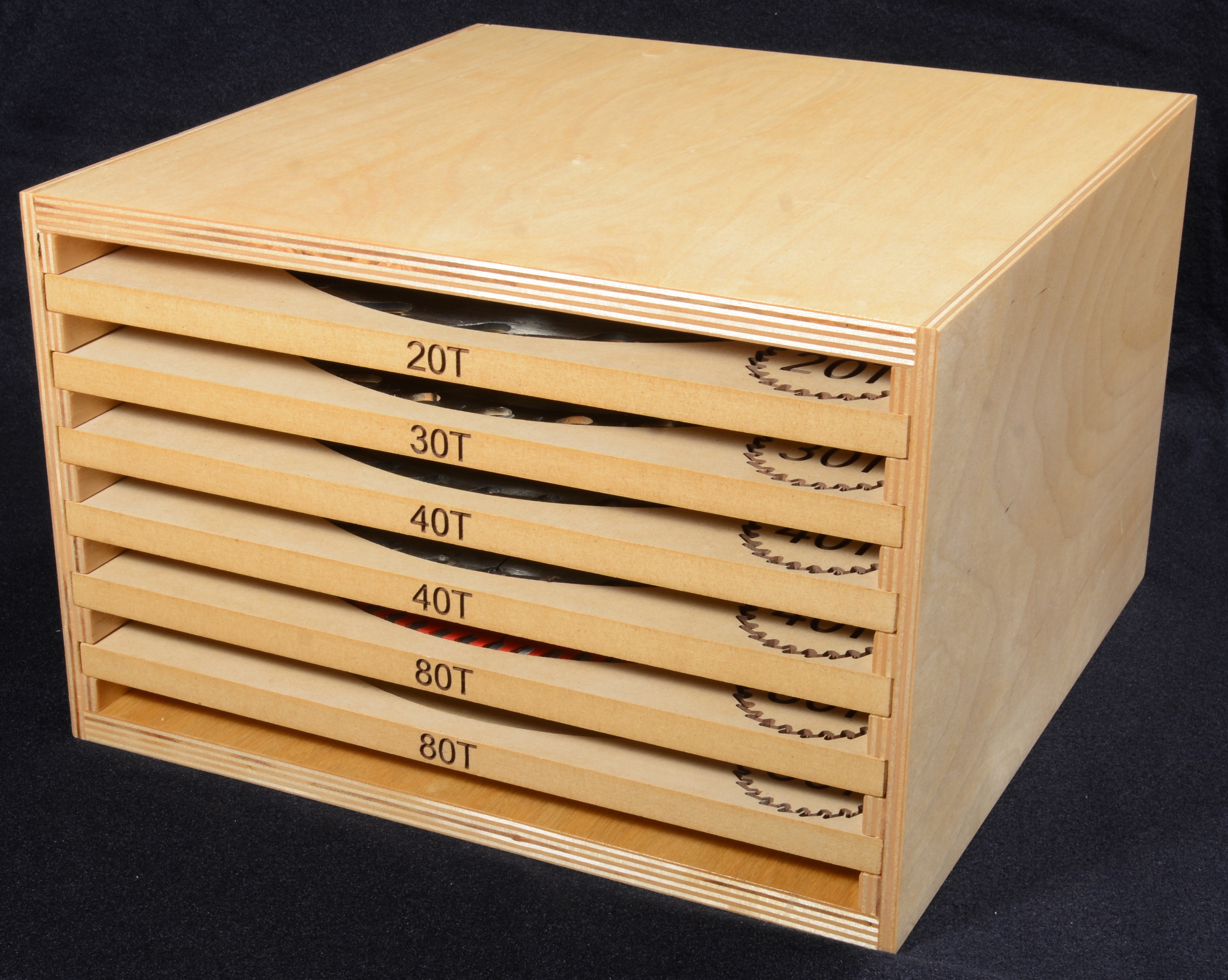
I got tired of storing my table saw blades in their shipping boxes:
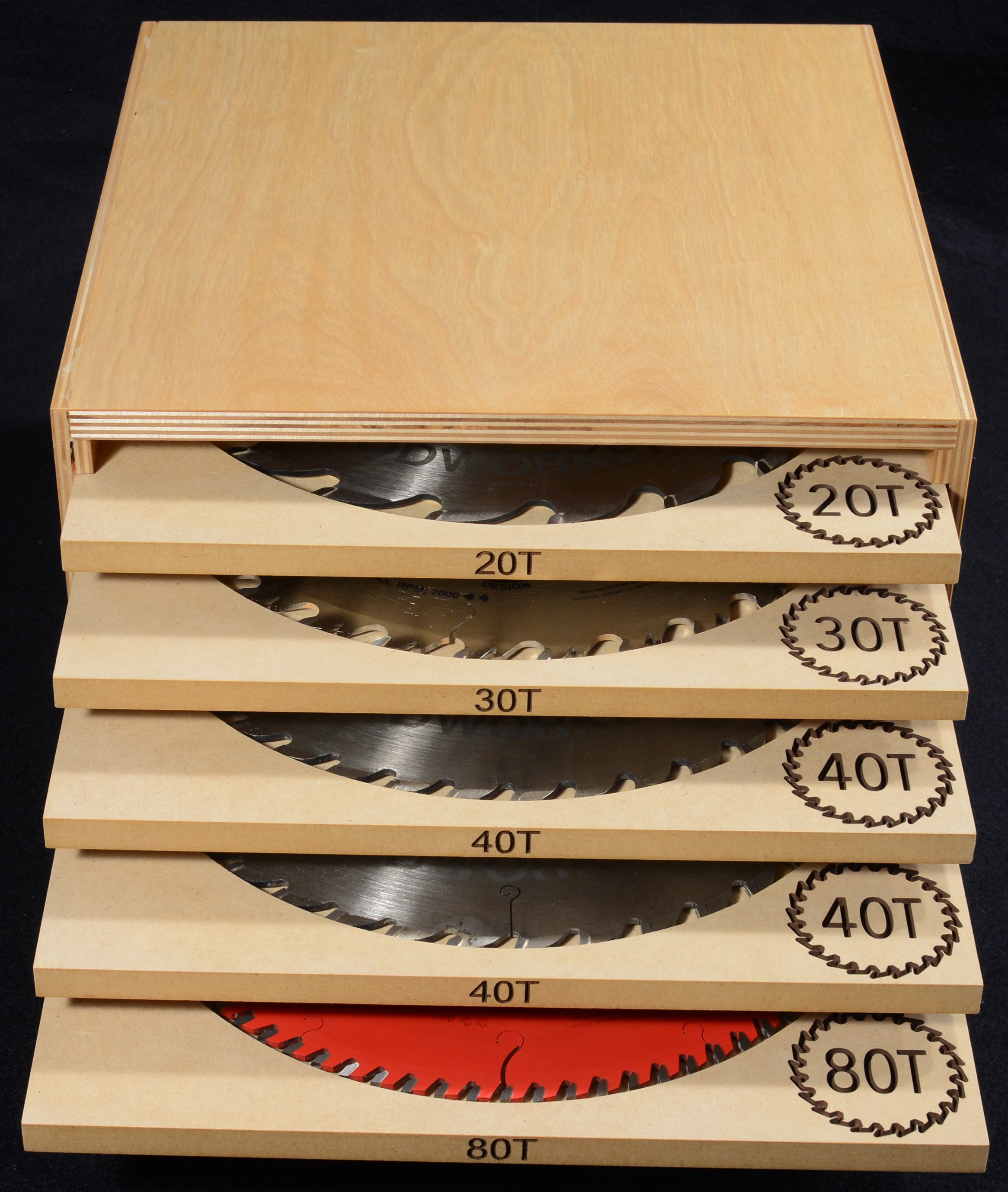
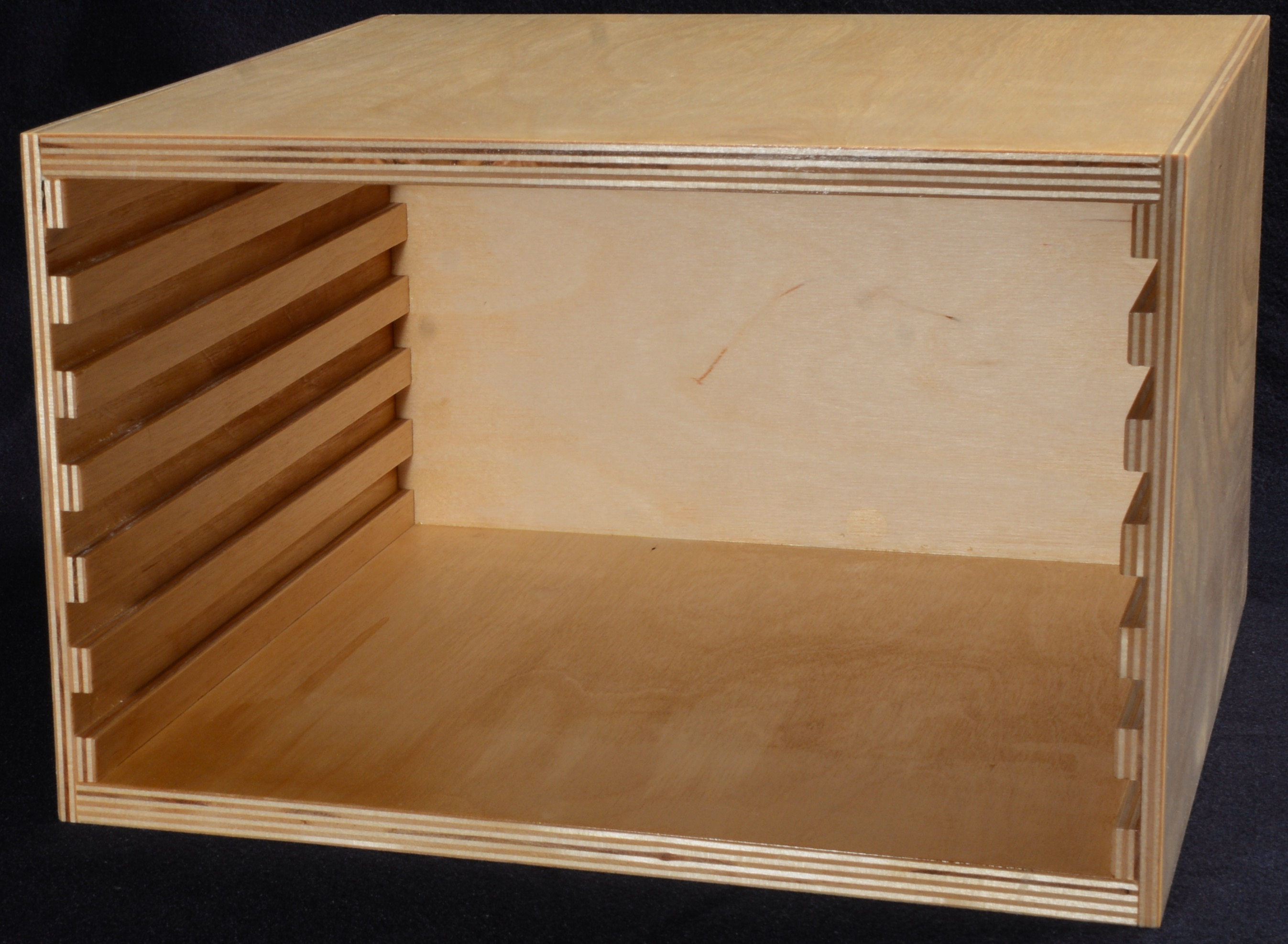
Started with individual trays, intending to just stack them, but then decided to add a box.
Trays are made from 1/2” MDF. There’s a “shelf” in the circular pocket to support the body of the blade, and a deeper relief around the outer edge so the blade teeth don’t rest on wood:
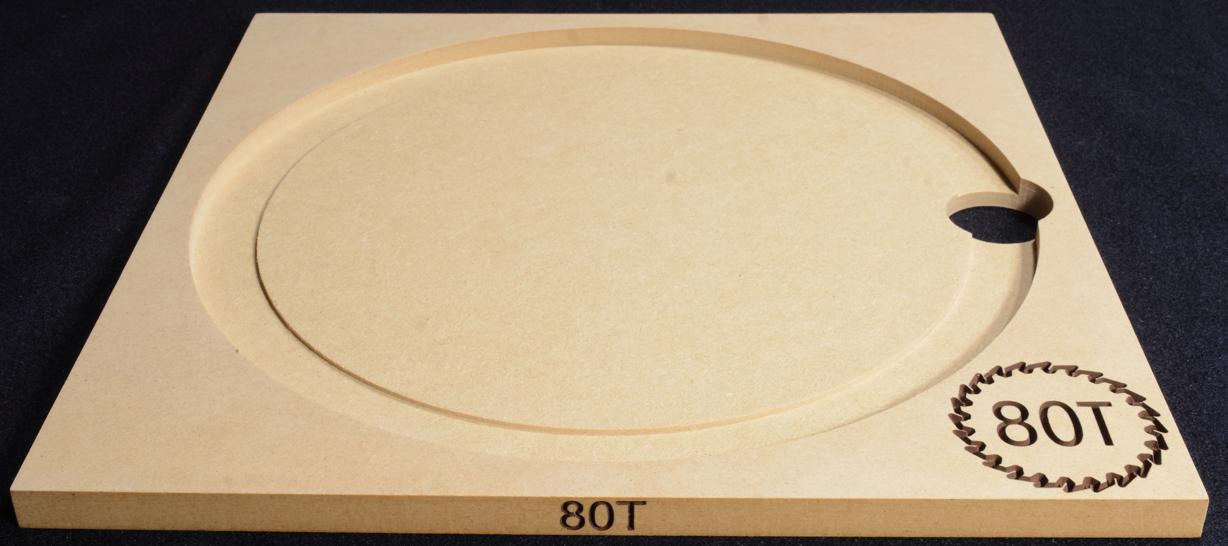
There’s also a finger hole to make it easy to remove the blade:
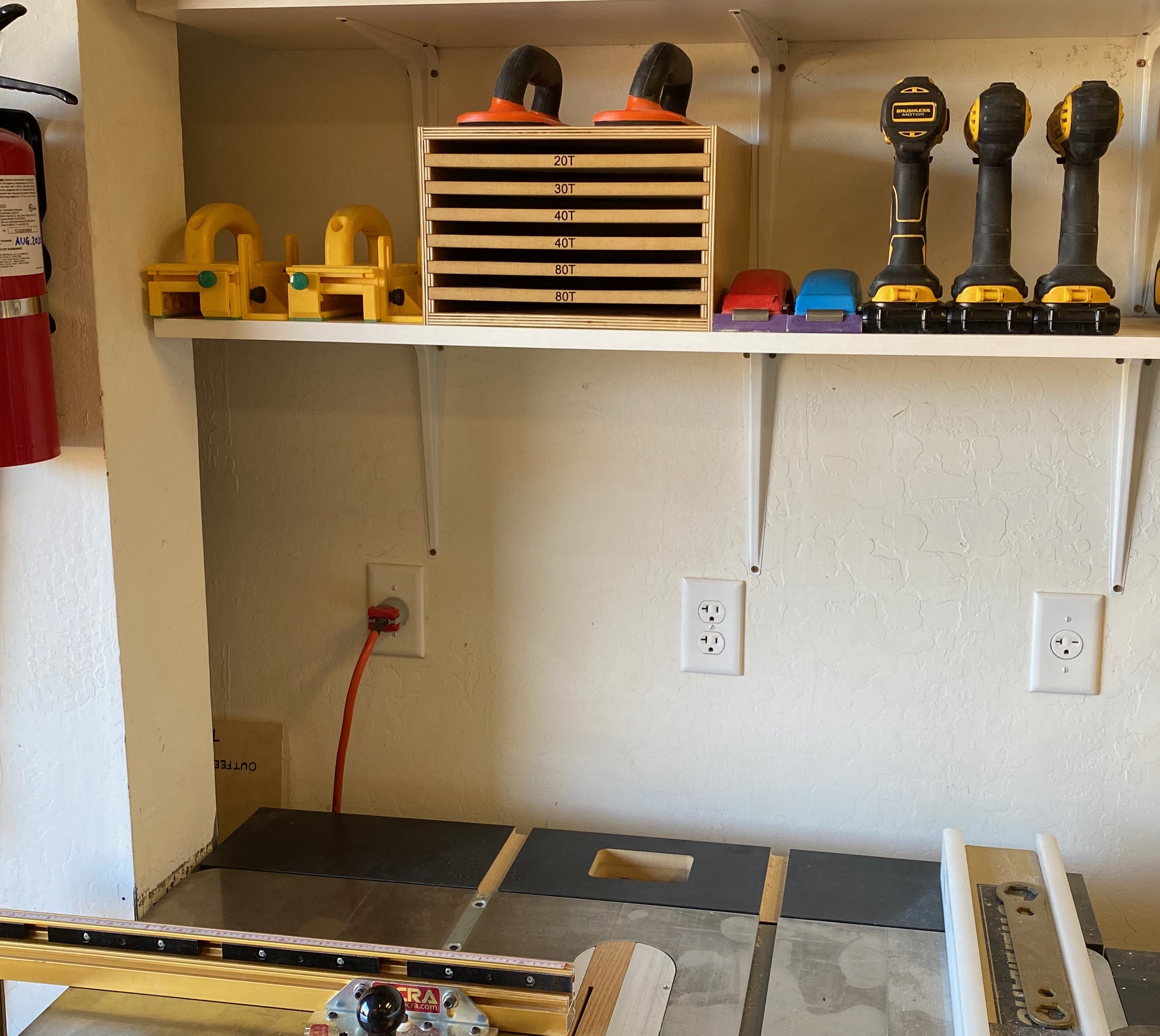
Stack 'o Trays:

The box is made from 1/2” baltic birch ply, finished with three coats of shellac:
New home above the table saw:
A 30-degree “V” bit was used to contour the saw blade logo and to V-Carve the tooth count on the face and edge of each tray. I first masked with Duck brand shelf liner, made the cuts, and then hit them with brown spray paint before peeling off the shelf liner.
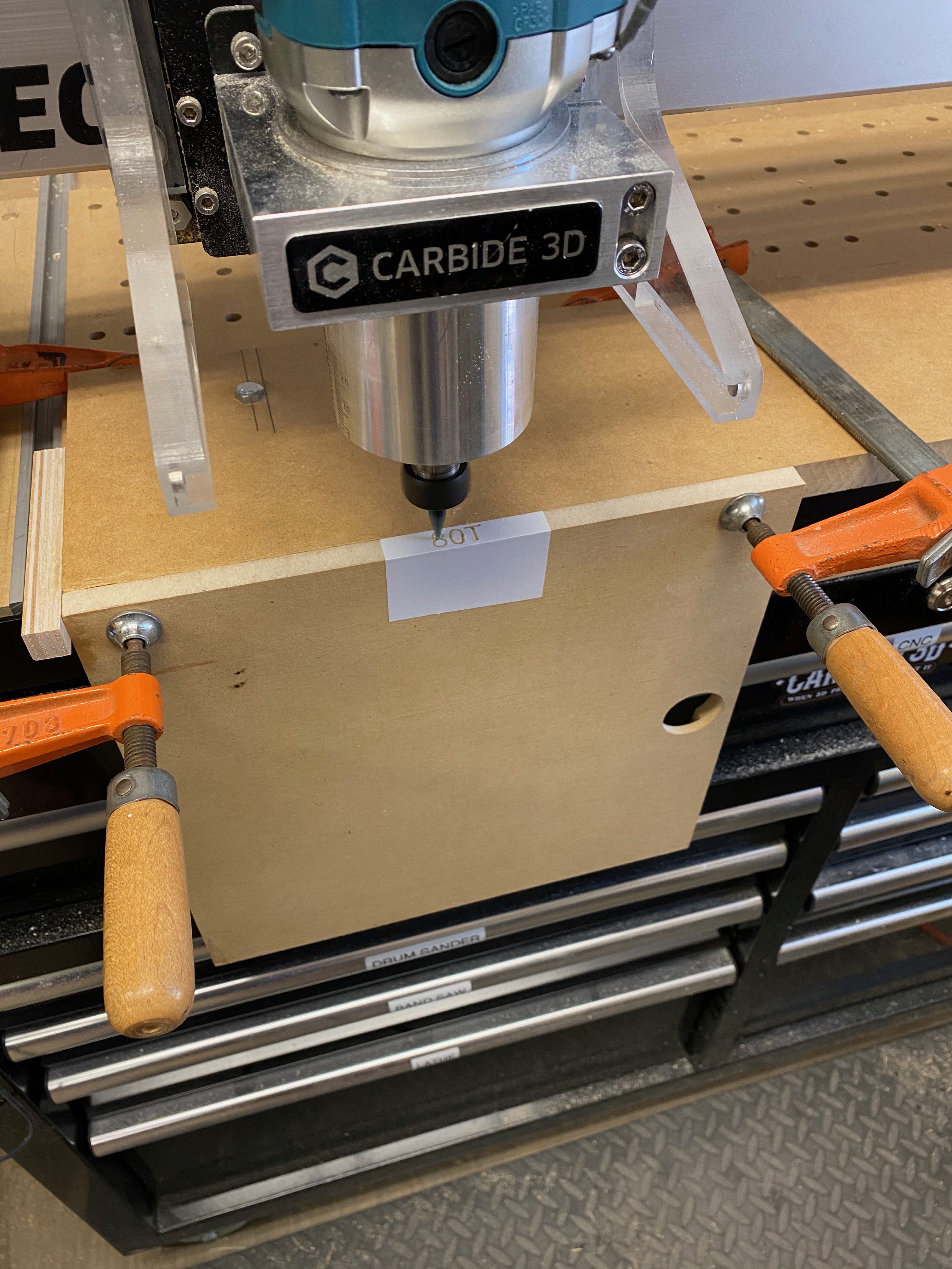
I’ve never truly appreciated the way the Shapeoko can travel past the front of the machine until now. I bolted a scrap to my wasteboard and used it to register each tray in a repeatable way to V-Carve the tooth count into the front edge:
The tray glide slots, back-edge rabbets and final profiles were all cut on the Shapeoko with a 1/4” downcut endmill. Here are the sides, both cut out of one piece of ply:

CARBIDE CREATE DESIGN FILES:
Box Back.c2d (6.0 KB) Box Sides.c2d (41.0 KB) Box Top and Bottom.c2d (14.0 KB) Saw Blade Tray.c2d (364.9 KB) Tray Edge Tooth Count.c2d (48.6 KB) Tray Face Tooth Count.c2d (152.9 KB)
CUTROCKET LINK:
19 Likes
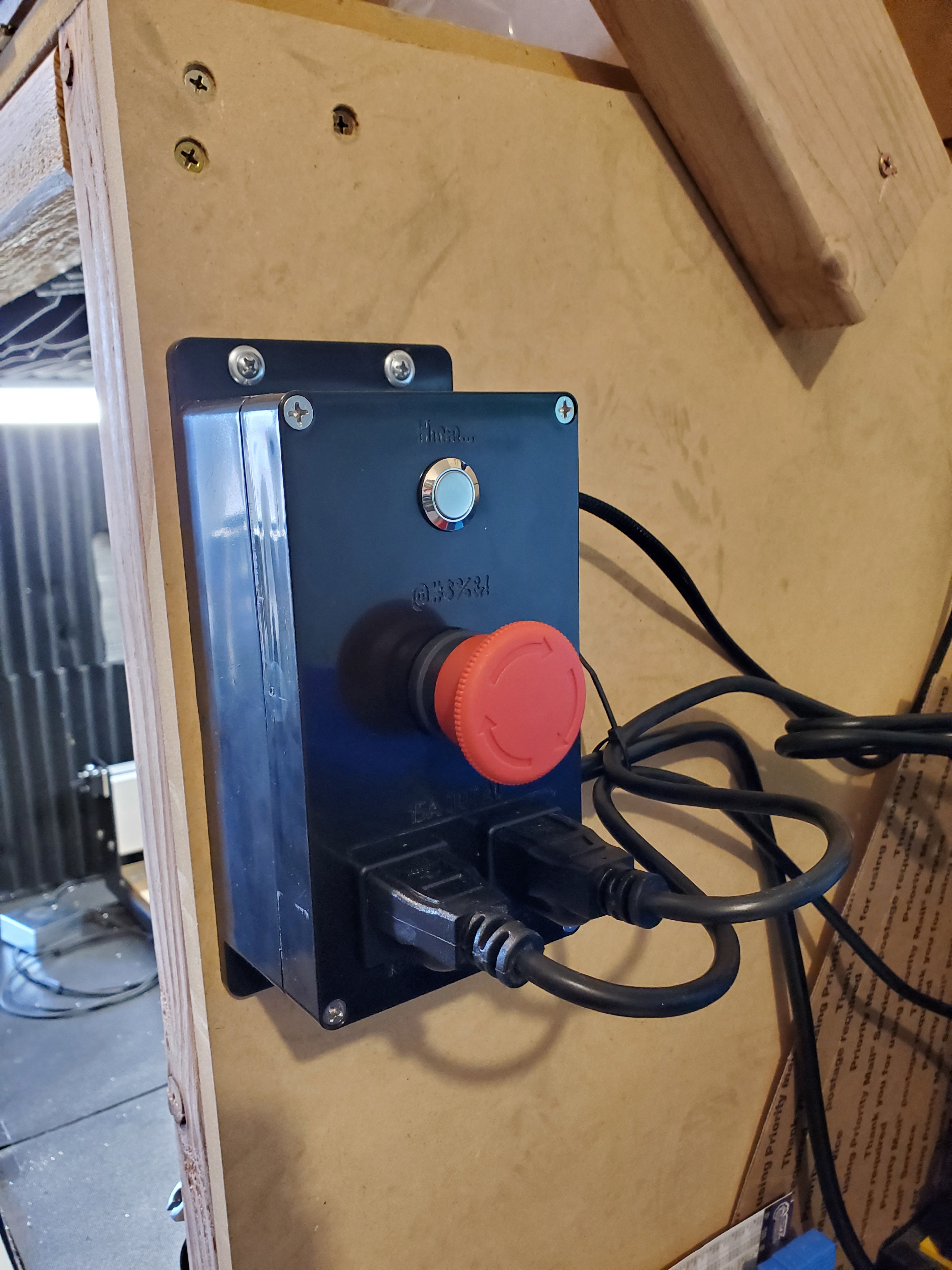
E-Stop/Pause Box
I wanted an E-stop and a hardware pause button in the same box. I also wanted to be able to shut off both the machine and router with a single E-stop. I have had the parts for quite a while and decided now was the time to make it.
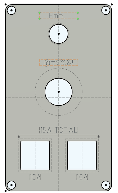
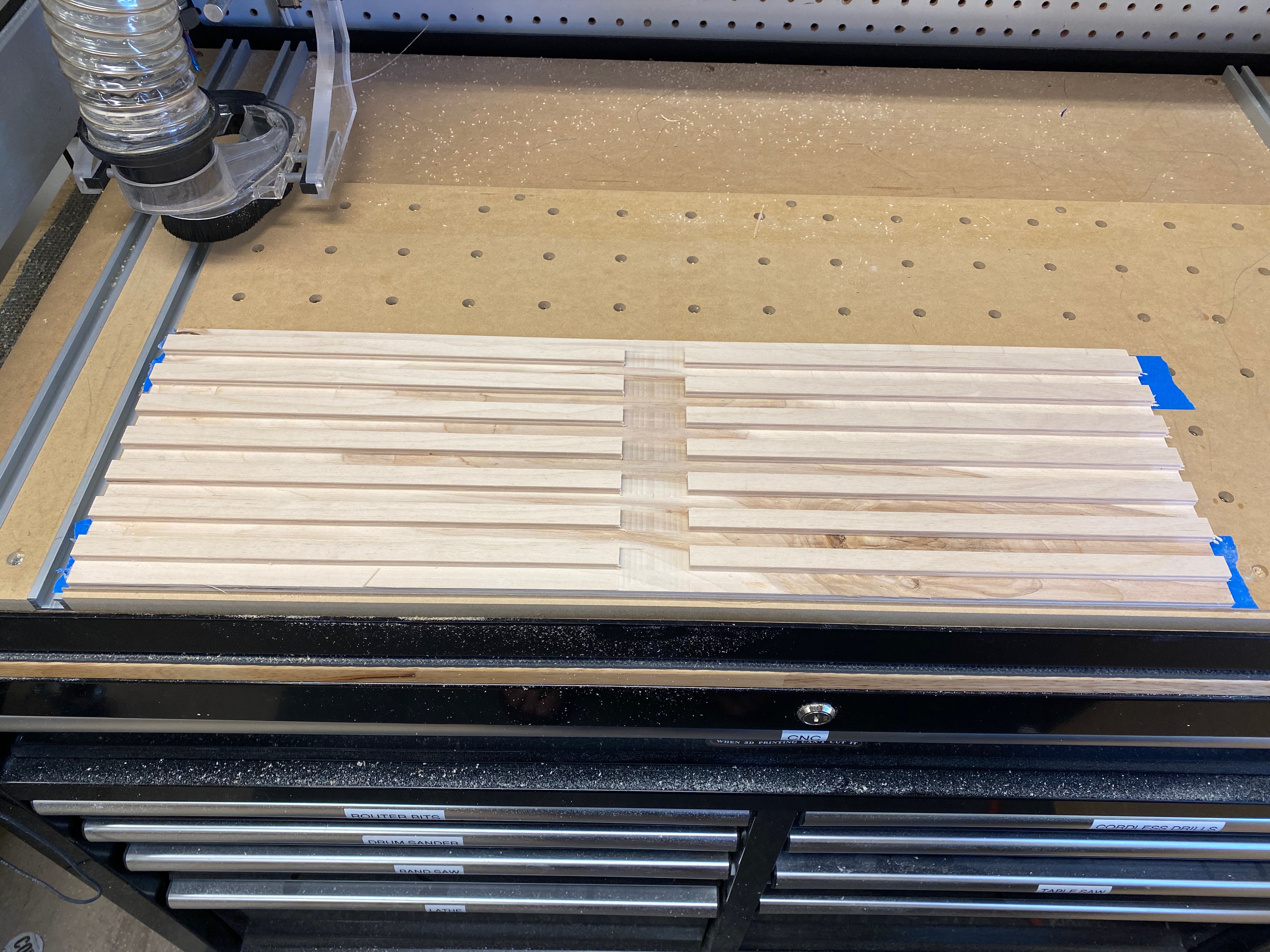
I made the design in Fusion 360 (the f3d file is attached as well as the step/dxf) and cut it out of an electronics project box I got off Amazon. I used a very small 3/64ths 2 flute to trace the lettering and a 3/32nds single flute to cut out the holes.
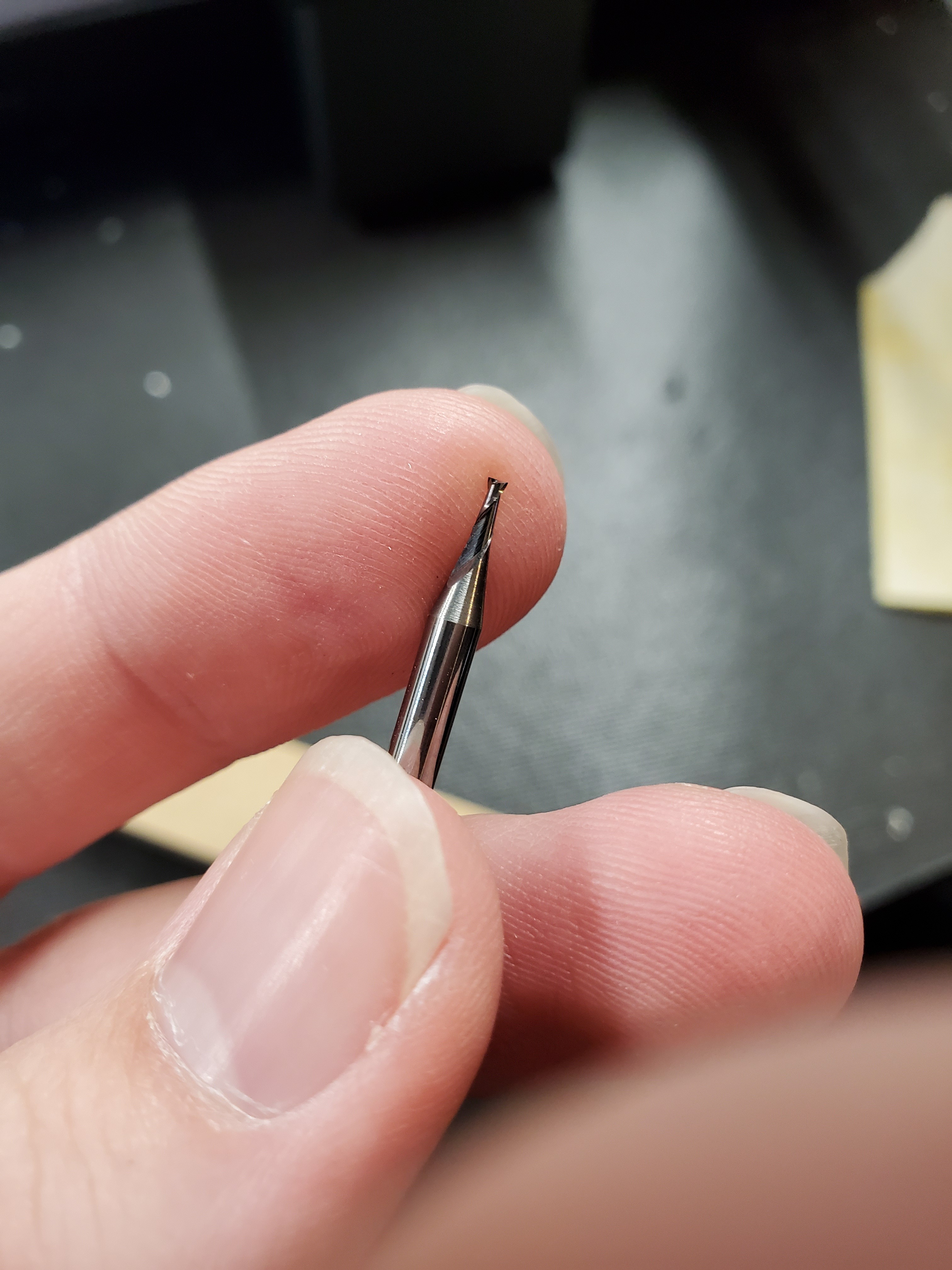
I am usually cut aluminum so my feeds and speeds were far to conservative. I was melting plastic rather than cutting anything, especially with the larger cutter. I ended up having to cut the RPM and go to 150% speed during the cut. Everything worked out but I would not suggest using the tool paths in the f3d file if you choose to make this. Work holding was pretty easy, I went overkill:


I had to put something under the rear edge of the part because it was not parallel with the table and caused the engraving tool path to not even touch on that side. The box is pretty cheap so it doesn’t surprise me that its not square. Here are the links to the parts I used as well as the files. I put it up on CutRocket but the uploader for files or pictures would not work for me.
Amazon parts:
https://www.amazon.com/dp/B006YZ7DJQ/?coliid=I3HL9QLGYR4MZF&colid=1OVW8S142RFOJ&psc=1&ref_=lv_ov_lig_dp_it
https://www.amazon.com/gp/product/B07KFCGFYF/ref=ppx_yo_dt_b_asin_title_o08_s00?ie=UTF8&psc=1
https://www.amazon.com/gp/product/B001OOMN88/ref=ppx_yo_dt_b_search_asin_title?ie=UTF8&psc=1
CutRocket Link:
Files:
E-Stop-Pause box v2 sketch.dxf (7.8 KB)
E-Stop-Pause box v2.zip (186.3 KB)
Final picture with painted engraving:

10 Likes
And if You use some white paint/marker in the engraved text it would be perfect.
Really like the way you cut the corner and edge face tooth count details, nicely done Steve.
Thanks for posting the links for the parts Nick, very helpful for us electrical neophytes!
You convinced me not to be lazy and I filled in the engraving with silver paint. I updated my post.
4 Likes
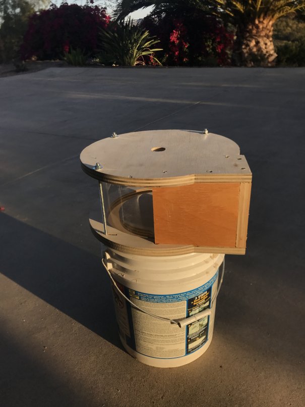
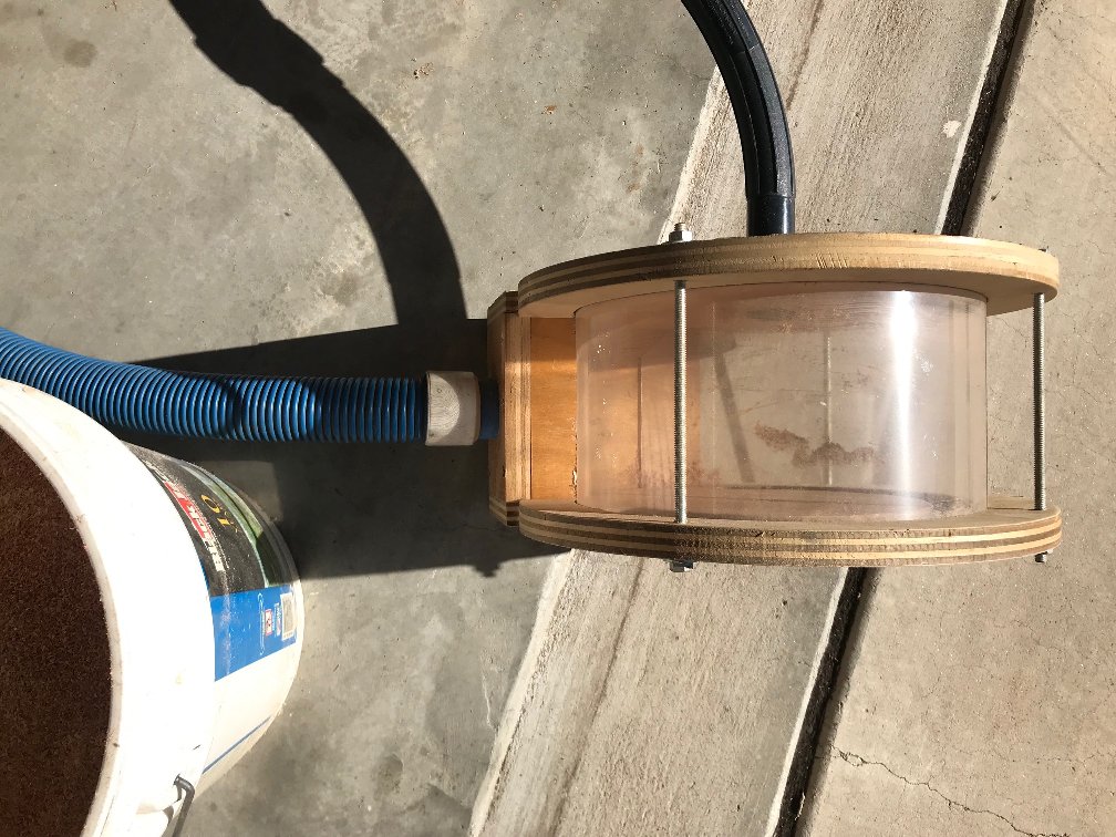
Thien Type Dust Collector
Not quite last minute, and I’m surprised one of these hasn’t been submitted yet, I thought I might as well write this up in the hopes it’ll help someone breathe less dust.
A dust collector was my second serious project using the ShapeOko after a couple of work holding clamps. After watching many excellent videos and reading multiple reviews, I decided that a Thien type dust would be the type I would build.
There are many designs out there, but I was after something on the smaller end of the spectrum and with a lesser parts count if possible and would fit on a standard five gallon bucket. This design has a total of 2 parts cut on the Shapeoko and 3 blocks cut on my table saw. In hindsight, I should have cut the plastic on the Shapeoko, but in this case I just scored and snapped with good results.
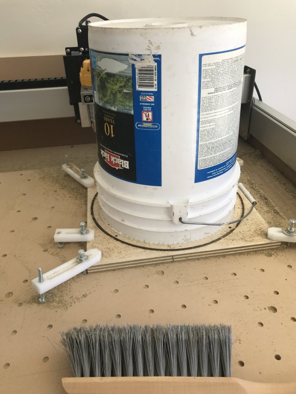
It was a challenge figuring out the workflow and double sided work holding back then, and being so new at CNC, that I’ve tried to write this description so a beginner would be able to easily grasp the steps.
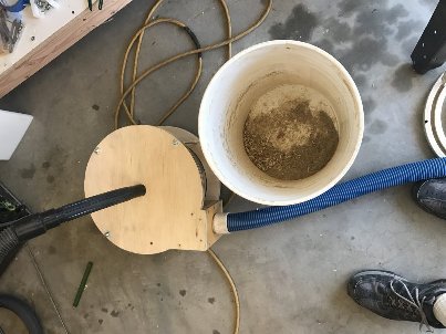
You’ll see in the pics below that cutting without a dust collector makes a real mess.
Step 1: Gather the materials
I used the following for this project:
- 1 - 2’ X 4’ X 3/4” ACX ply from your local purveyor, about $22 in my area. Or a similar size less expensive piece, I just happened to have the ACX on hand.
- 1 piece clear (If you want to see the chips being collected) acrylic sheet 7” X 36”. The design will accommodate up to 1/8” thick, but my Saturday night CAD supply store only had .093” X 20” X 36” which worked perfectly, about $18. Using something thinner and thus more flexible is a workable option.
- 1 – 36” X ¼”-20 all thread rod, $2. Cut 3 pieces 7.25”
- 6 – ¼”-20 nuts, $0.36
- 6 – ¼” washers $0.30
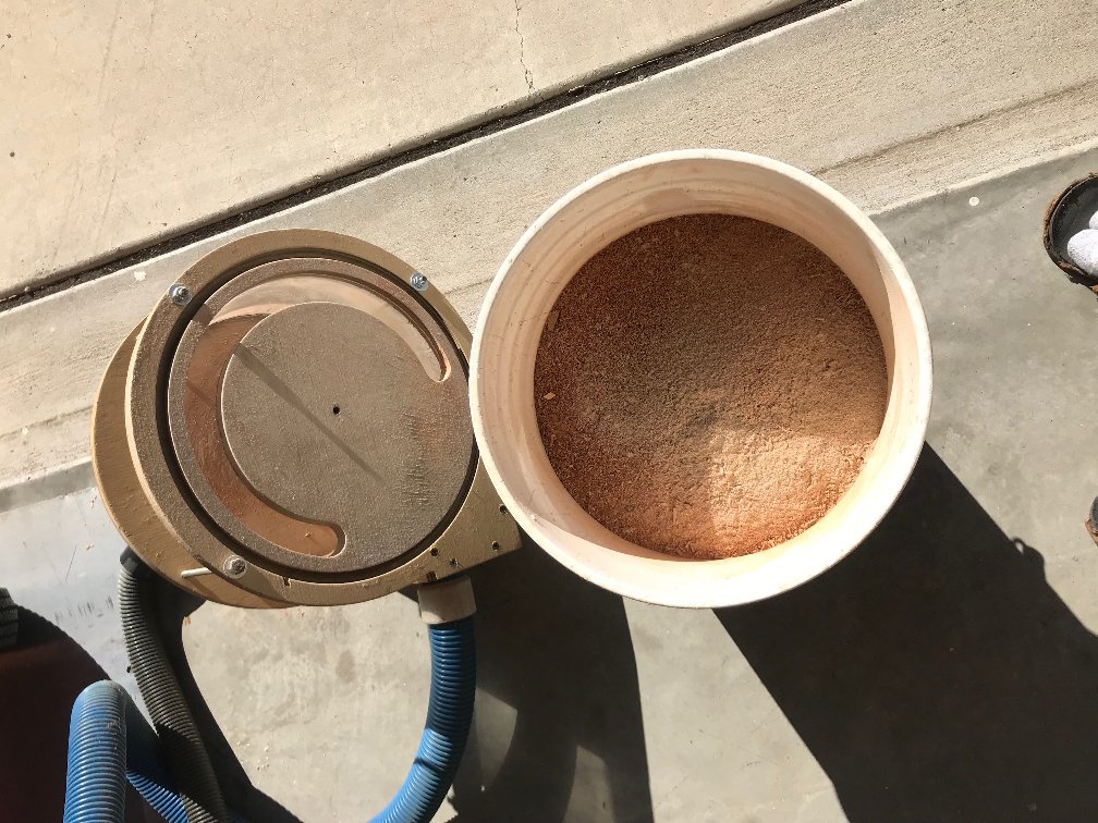
- 1 - 5 gallon bucket. I had a paint bucket on-hand, but a Homer bucket or similar should work. All the buckets I checked had the same diameter and lip size at the top.
- Here are the Carbide Create .c2d files:
- And here are the DXF files if you’re using a CAD program other than Carbide Create.
The Carbide Create Steps
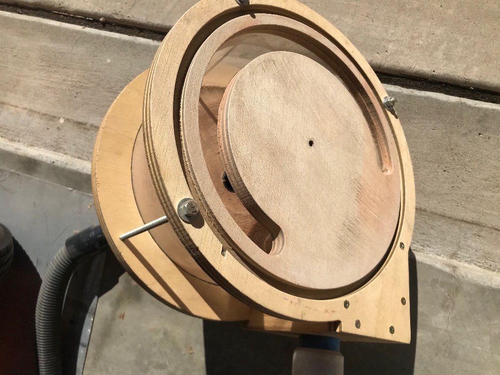
Step 2: Collector Lid
- Open the Dust_Separator_Lid.c2d in Carbide Create. Don’t worry about the letter ‘B’ you’ll see, I only used this as my reference to know I was working on the bottom of the top piece.
- Check the stock thickness from the Job Setup page. These files are set to 0.720” but most plywood varies in thickness and you should reset this to accommodate your material.
- In Design mode, check and confirm the width of the cuts for the inlet blocks and adjust as necessary for the material you’ll be using. For help with checking the dimensions in Carbide Create, check this video:
https://youtu.be/QwtRf-x3vLQ
Thank you @WillAdams for pointing me to this. - Still in Design mode, check radius/ diameter for your center vacuum hole. I’m using and old house vacuum which accounts for the small size in this drawing, but you’ll want to adjust the size for your vacuum hose or the adapter that you’ve already made on your 3D printer ;-).
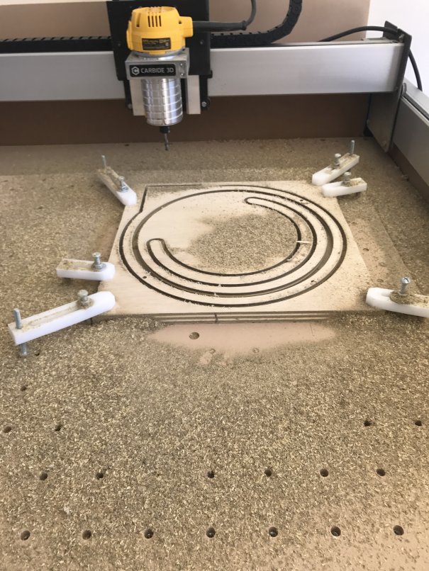
- In the Toolpath mode, check the toolpath depths for the Through Bolt Holes, Vacuum Hose Center Hole and Outside Cutout. You’ll want them a couple of thousandths less than your material thickness unless you don’t mind cutting into your wasteboard, but that what it’s there for, right? I just sanded the few thousandths that were left over from the reverse side and it turned out great.
- Still in Toolpath mode, disable all of the jobs except the Cylinder Wall Slot by right clicking on each and selecting ‘Disable.’
- Save the Gcode for the Cylinder Wall Slot cut with an appropriate name, I used ‘1 -Top Cyl Wall Slot’. Using a ‘1’ at the file name start helps me remember which job I’ll be running first at machining time. I used the Carbide Create default tool cutting values for the entire project and they worked fine. You can see these values by double-clicking each of the toolpaths to open the dialog box.
- Now disable the Cylinder Wall Slot and enable the remaining four toolpaths by right clicking on each. Save the Gcode with an appropriate name. I used ‘Dust Separator Lid’.
Note: The reason for two separate jobs is a required bit change after the cylinder wall slot is cut using a 0.125 end mill. More on tool changes here: http://docs.carbide3d.com/tutorials/tool-change/
Step 3: Collector Base – Top Side
- Open the Dust_Separator_Base_Bottom.c2d. The text “Top” is here just to verify which side of the piece is being worked on.
- Check the stock thickness from the Job Setup page. These files are set to 0.720” but most plywood varies. Also note that the Toolpath zero point is set to the center of the piece. We’ll be using this to help with recentering when we flip the piece to machine the other side.
- In Design mode, check and confirm the width of the cuts for the inlet blocks and adjust as necessary for the material you’ll be using. See step 2, item 3 for a refresher if needed.
- In the Toolpath mode, check the toolpath depth for the Centering hole. You’ll want this at or a couple of thousandths less than your material thickness.
- Still in Toolpath mode, disable all of the jobs except the Cylinder Wall Slot by right clicking on each and selecting ‘Disable.’
- Save the Gcode for the Cylinder Wall Slot cut with an appropriate name, such as ‘Collector Base Cylinder Wall Slot’. Again, I used the Carbide Create default tool speed values for the entire project and they worked fine.
- Now disable the Cylinder Wall Slot and enable the remaining toolpaths. Save the Gcode with an appropriate name.
Step 3A: Collector Base – Bottom Side
- Open the Dust_Separator_Base_Top.c2d file
- Check the stock thickness from the Job Setup page.
- In the toolpath mode, you’ll be able to enable all f the toolpaths to create one single cut file since the same bit is used for all operations. Save the Gcode with an appropriate name.
Machining the Parts
I cut the 2’ X 4’ plywood down to 2 - 14” X 14” pieces on the table saw to make them easier to set square on the Shapeoko table. Not knowing about all of the two-sided machining tricks like doweling made this ahem, trickier for the bottom piece that required cuts to both sides.
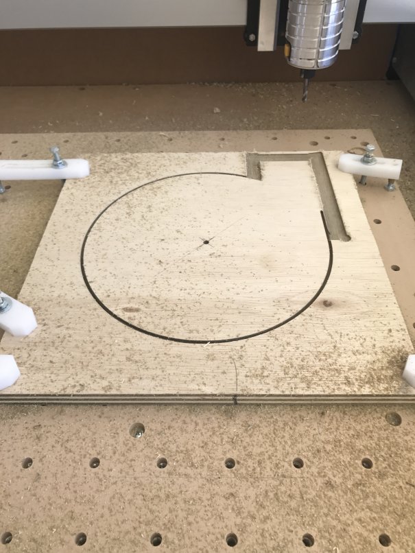
Step 4: Lid
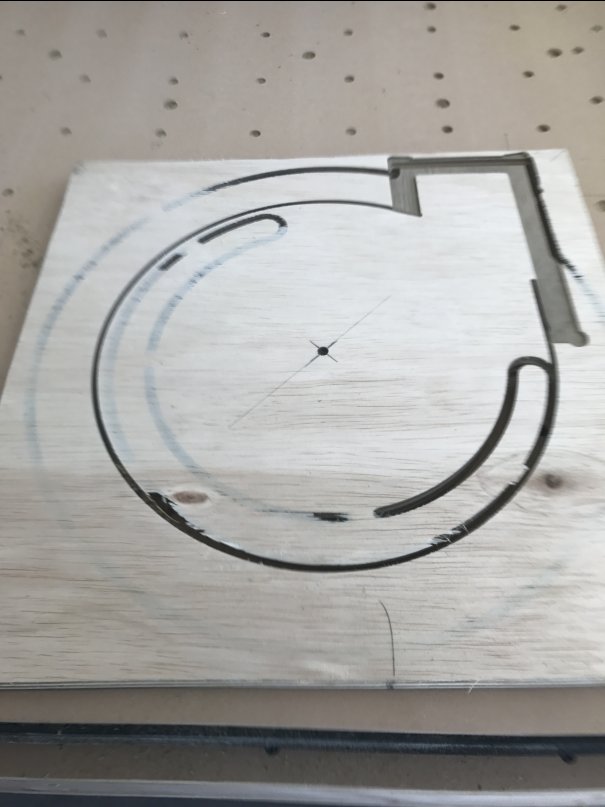
- I started with the Collector lid since it was a single sided machining operation. To get the plywood center to match the toolpath zero point, I carefully drew a line from each corner, which turned out good enough for this project. As seen in the photo below.
- Line the plywood edge that is closest to you along the X axis. I had previously engraved .010” lines on both the X and Y every 4” using a 90 v-bit, so this was an easy alignment.
- To get the exact toolpath XY zero, I inserted a v-bit and centered this on the marks in step one.
- Change to the bit used in your first toolpath and zero Z to the material surface.
- Run the toolpaths saved in step 2 above.
Step 5: Collector Base Bottom Side
-
For the base, which requires two sided machining, I again drew a line from each corner, on both sides, to find the material center.
-
Repeat steps 2 and 3 from the previous step 4 to find XY zero.
-
Change to the bit used in your first toolpath and zero Z to the material surface.
-
Run the toolpaths created for the base bottom from step 3.
-
Now the tricky part setting up for the second side. Leave the bit in the router and move the router clear of the work area.
-
Flip the plywood, and place it close to the X baseline you just used.
-
Bring the router back to the current XY zero.
-
Carefully lower the bit moving the plywood until the bit is below the surface in the center hole cut when you ran the toolpaths on the base bottom.
-
Make certain that the plywood edge facing you is running parallel along the X baseline, very important to get the alignment needed for the top cuts.
-
Run the toolpath for the block recesses created in step 3.7.
-
Change to a 1/8” end mill and run the toolpath created in step 3.5.
Step 6: The 3 Blocks
-
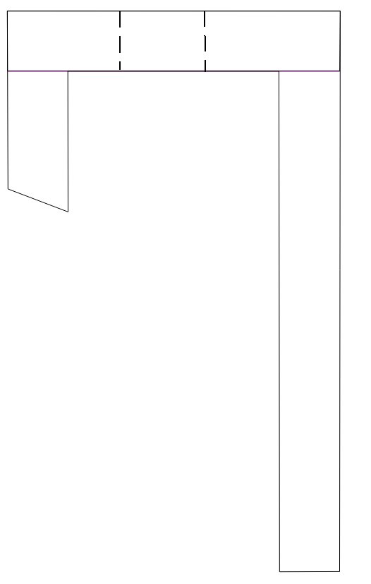
I cut the three blocks from scrap left over from the above operations using a table saw. Three blocks are required, all 5.25” tall and 2”, 4” and 6” long.
-
Make a center point in the 2.5” X 5.25” piece and drill an inlet hole the size of the vacuum adaptor that connects to your Sweepy or other dust collector.
-
The 2” X 5.25 block will need a 20 degree angle on the edge that abuts the plastic piece, which is visible in the Dust_Separator_Lid.c2d and Dust_Separtator_Base_Top.c2d files.
-
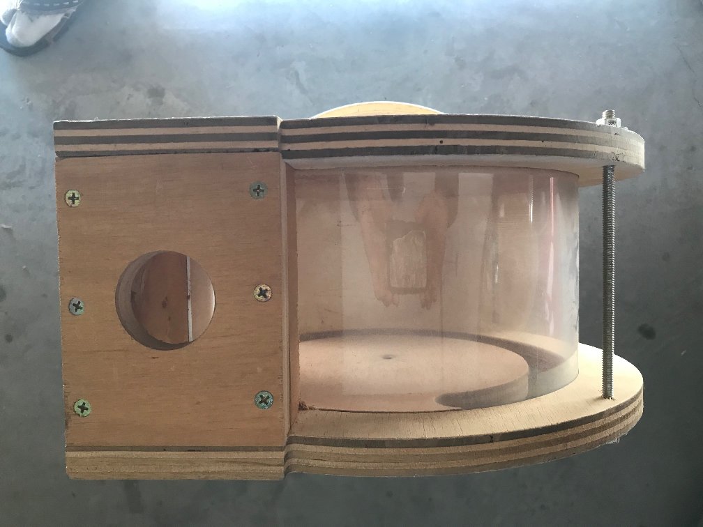
Assemble the blocks as shown. I glued and screwed this together.
-
Attach the block assembly to the top piece with screws. I didn’t use glue as I might need to replace the plastic someday.
-
Cut the plastic 5.625” high and overcut the length. I measured just over 29” so I cut 30”
-
Insert the plastic into the slot in the top with the blocks bending carefully. Check, mark and cut the final length.
-
Put nuts and washers on one side of the allthread pieces, reinsert the plastic.
-
Now trap the blocks and plastic with the bottom piece and insert the allthread pieces.
-
Add nuts and washers to secure the assembly. I did not use glue to make disassembly easy should it ever be required. The plastic bending against the cuts it’s trapped in seals really well.
Mistakes and Tips:
Measure the plywood that you acquire from your supplier as thicknesses can vary by several thousandths or more in some cases. This almost caught me thinking the ¾” meant, .750 which is not the case!
I fully expected to see chipping while milling the plywood and wasn’t disappointed. You can limit this chipping with a down cut bit (which I didn’t know existed then) but I was after function rather than form.
Setting the plastic in the sun or other warm spot would make it much easier to bend to the cutout radius.
This works really well even though it’s got a recycled house vacuum power:
Carbide 3D Files
Dust_Separator_Base_Top.c2d (394.3 KB) Dust_Separator_Lid.c2d (682.6 KB) Dust_Separator_Base_Bottom.c2d (305.4 KB)
And finally, the CutRocket link:
11 Likes