Community challenge #15: Workshop accessory (closed)

This evening’s remaining task is to trim down several Bamboo inlays, so the machine will get a workout - I have no doubt the tensioners will hold firm, but will be interesting to see.

Then, finally, I can fit my HDZ knowing that all ‘must do’ tasks are finished, and I can afford some tinker time to get the HDZ setup exactly…

2 Likes

-Thanks for uploading the pics, looks pretty nice on there congratulations!

1 Like

Nice to see the adjuster screw on the belt clamp clears the pulley track. I know it was factored in during design measurements, but nice to see achieved;

Also pulled out the 6mm steel GT2 belts that had been an stop-gap, and fitted the 9mm GT2. Fitting them was a breeze: feed belt through slot, under snail-cam, pull tight by hand, lock, adjust tension with spanner. Done. In the words of Strictly: FAB-U-LOUS :wink:

1 Like

Ran a trimming/surfacing cut on an Oak inlay, using my 1" End Mill. The cut was intentionally aggressive, chips (good size chips) flying everywhere, and 30 mins total - and the adjustable belt clamps didn’t shift at all. The exact same ‘ping tone’ on both belts before and after the cut. Happy days!! Now to make the arms for a third clamp and fit it to the X gantry :slight_smile:

Third clamp finished and fitted to the Y1 end of the X gantry. Then spent the afternoon installing the impressive HDZ and proximity sensors, and pleased that the new (now dubbed HD Clamps :wink: ) belt clamps really simplified the re-fit of the X belt and tensioning. Doubly happy.

Trammed and ready for a 2,5D carve of a dragon I’ve been pondering.

IMG_5174

The Dragon project coming together… Just finishing off wiring and fitting my new 800W spindle, then will run this :slight_smile:

2 Likes

Final week-end. Come on, you know we love last minute entries!

1 Like

SAW BLADE CADDY


I got tired of storing my table saw blades in their shipping boxes:

Started with individual trays, intending to just stack them, but then decided to add a box.

Trays are made from 1/2” MDF. There’s a “shelf” in the circular pocket to support the body of the blade, and a deeper relief around the outer edge so the blade teeth don’t rest on wood:

There’s also a finger hole to make it easy to remove the blade:

Stack 'o Trays:

The box is made from 1/2” baltic birch ply, finished with three coats of shellac:

New home above the table saw:

A 30-degree “V” bit was used to contour the saw blade logo and to V-Carve the tooth count on the face and edge of each tray. I first masked with Duck brand shelf liner, made the cuts, and then hit them with brown spray paint before peeling off the shelf liner.

I’ve never truly appreciated the way the Shapeoko can travel past the front of the machine until now. I bolted a scrap to my wasteboard and used it to register each tray in a repeatable way to V-Carve the tooth count into the front edge:

The tray glide slots, back-edge rabbets and final profiles were all cut on the Shapeoko with a 1/4” downcut endmill. Here are the sides, both cut out of one piece of ply:


CARBIDE CREATE DESIGN FILES:
Box Back.c2d (6.0 KB) Box Sides.c2d (41.0 KB) Box Top and Bottom.c2d (14.0 KB) Saw Blade Tray.c2d (364.9 KB) Tray Edge Tooth Count.c2d (48.6 KB) Tray Face Tooth Count.c2d (152.9 KB)

CUTROCKET LINK:

19 Likes

E-Stop/Pause Box
I wanted an E-stop and a hardware pause button in the same box. I also wanted to be able to shut off both the machine and router with a single E-stop. I have had the parts for quite a while and decided now was the time to make it.


I made the design in Fusion 360 (the f3d file is attached as well as the step/dxf) and cut it out of an electronics project box I got off Amazon. I used a very small 3/64ths 2 flute to trace the lettering and a 3/32nds single flute to cut out the holes.

I am usually cut aluminum so my feeds and speeds were far to conservative. I was melting plastic rather than cutting anything, especially with the larger cutter. I ended up having to cut the RPM and go to 150% speed during the cut. Everything worked out but I would not suggest using the tool paths in the f3d file if you choose to make this. Work holding was pretty easy, I went overkill:


I had to put something under the rear edge of the part because it was not parallel with the table and caused the engraving tool path to not even touch on that side. The box is pretty cheap so it doesn’t surprise me that its not square. Here are the links to the parts I used as well as the files. I put it up on CutRocket but the uploader for files or pictures would not work for me.

Amazon parts:
https://www.amazon.com/dp/B006YZ7DJQ/?coliid=I3HL9QLGYR4MZF&colid=1OVW8S142RFOJ&psc=1&ref_=lv_ov_lig_dp_it

https://www.amazon.com/dp/B0036ZA94S/?coliid=I28DU8WYOMHS4E&colid=1OVW8S142RFOJ&psc=1&ref_=lv_ov_lig_dp_it

https://www.amazon.com/dp/B07NXPPKDZ/?coliid=IPDFF9J33COOO&colid=1OVW8S142RFOJ&psc=1&ref_=lv_ov_lig_dp_it

https://www.amazon.com/dp/B07R8PTTDX/?coliid=I2OCKSZFSKP68N&colid=1OVW8S142RFOJ&psc=1&ref_=lv_ov_lig_dp_it

https://www.amazon.com/gp/product/B07KFCGFYF/ref=ppx_yo_dt_b_asin_title_o08_s00?ie=UTF8&psc=1

https://www.amazon.com/gp/product/B001OOMN88/ref=ppx_yo_dt_b_search_asin_title?ie=UTF8&psc=1

CutRocket Link:

Files:
E-Stop-Pause box v2 sketch.dxf (7.8 KB)
E-Stop-Pause box v2.zip (186.3 KB)

Final picture with painted engraving:

10 Likes

And if You use some white paint/marker in the engraved text it would be perfect.

Really like the way you cut the corner and edge face tooth count details, nicely done Steve.

Thanks for posting the links for the parts Nick, very helpful for us electrical neophytes!

You convinced me not to be lazy and I filled in the engraving with silver paint. I updated my post.

4 Likes

Thien Type Dust Collector

Not quite last minute, and I’m surprised one of these hasn’t been submitted yet, I thought I might as well write this up in the hopes it’ll help someone breathe less dust.

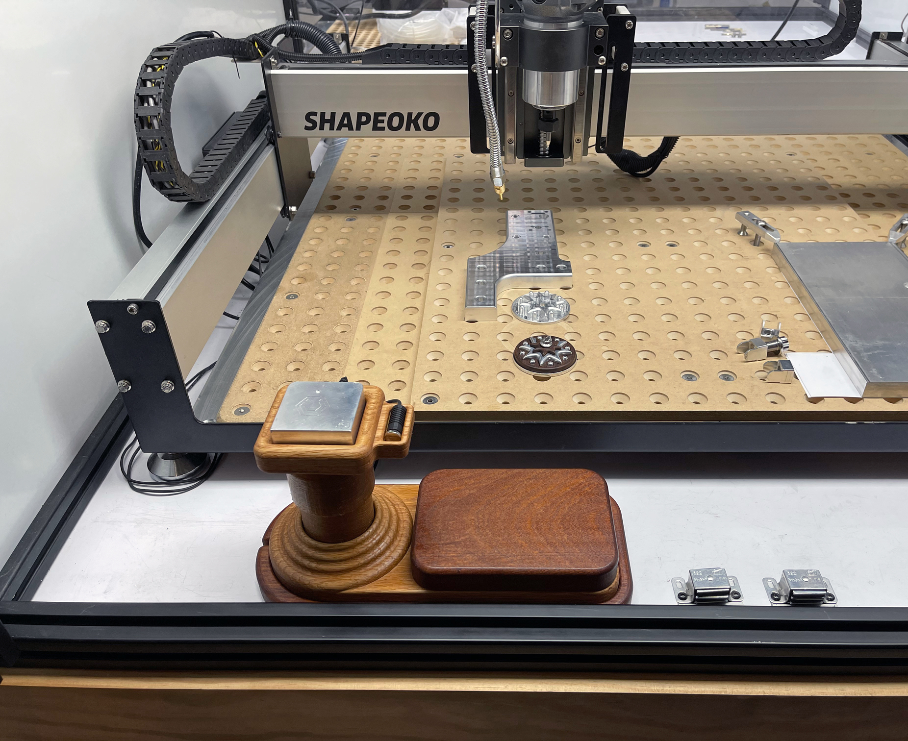
A dust collector was my second serious project using the ShapeOko after a couple of work holding clamps. After watching many excellent videos and reading multiple reviews, I decided that a Thien type dust would be the type I would build.

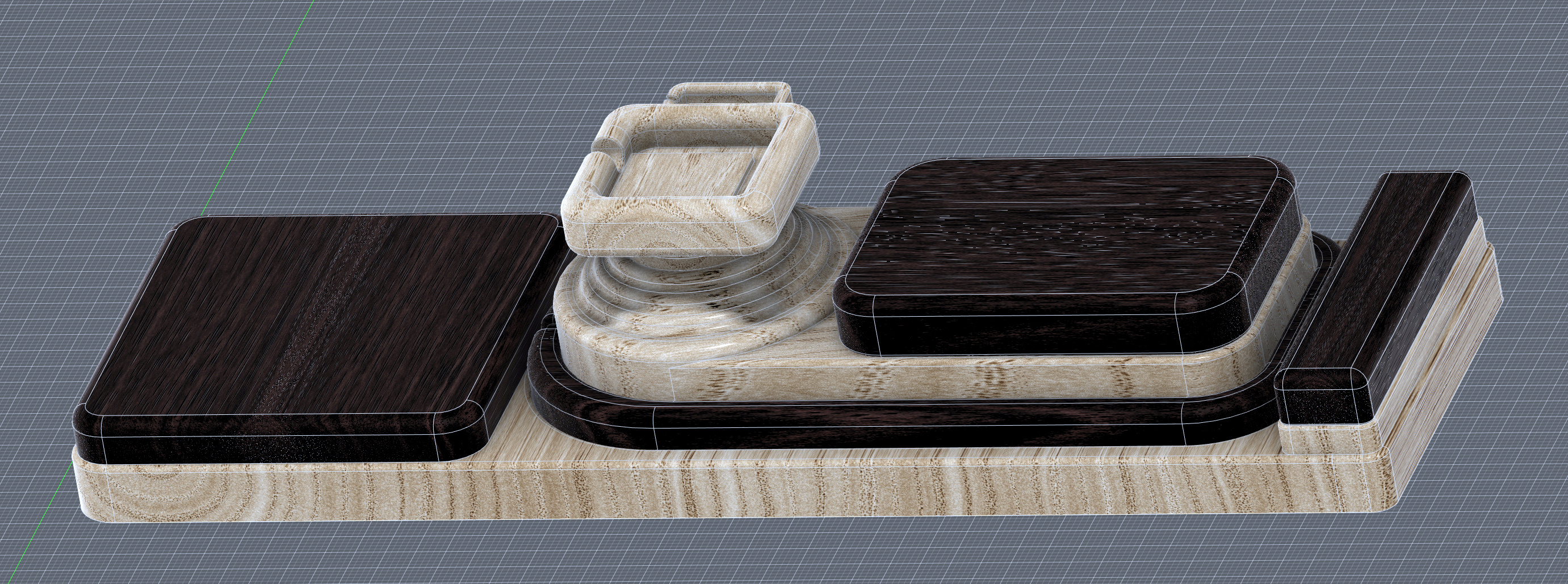
There are many designs out there, but I was after something on the smaller end of the spectrum and with a lesser parts count if possible and would fit on a standard five gallon bucket. This design has a total of 2 parts cut on the Shapeoko and 3 blocks cut on my table saw. In hindsight, I should have cut the plastic on the Shapeoko, but in this case I just scored and snapped with good results.

It was a challenge figuring out the workflow and double sided work holding back then, and being so new at CNC, that I’ve tried to write this description so a beginner would be able to easily grasp the steps.

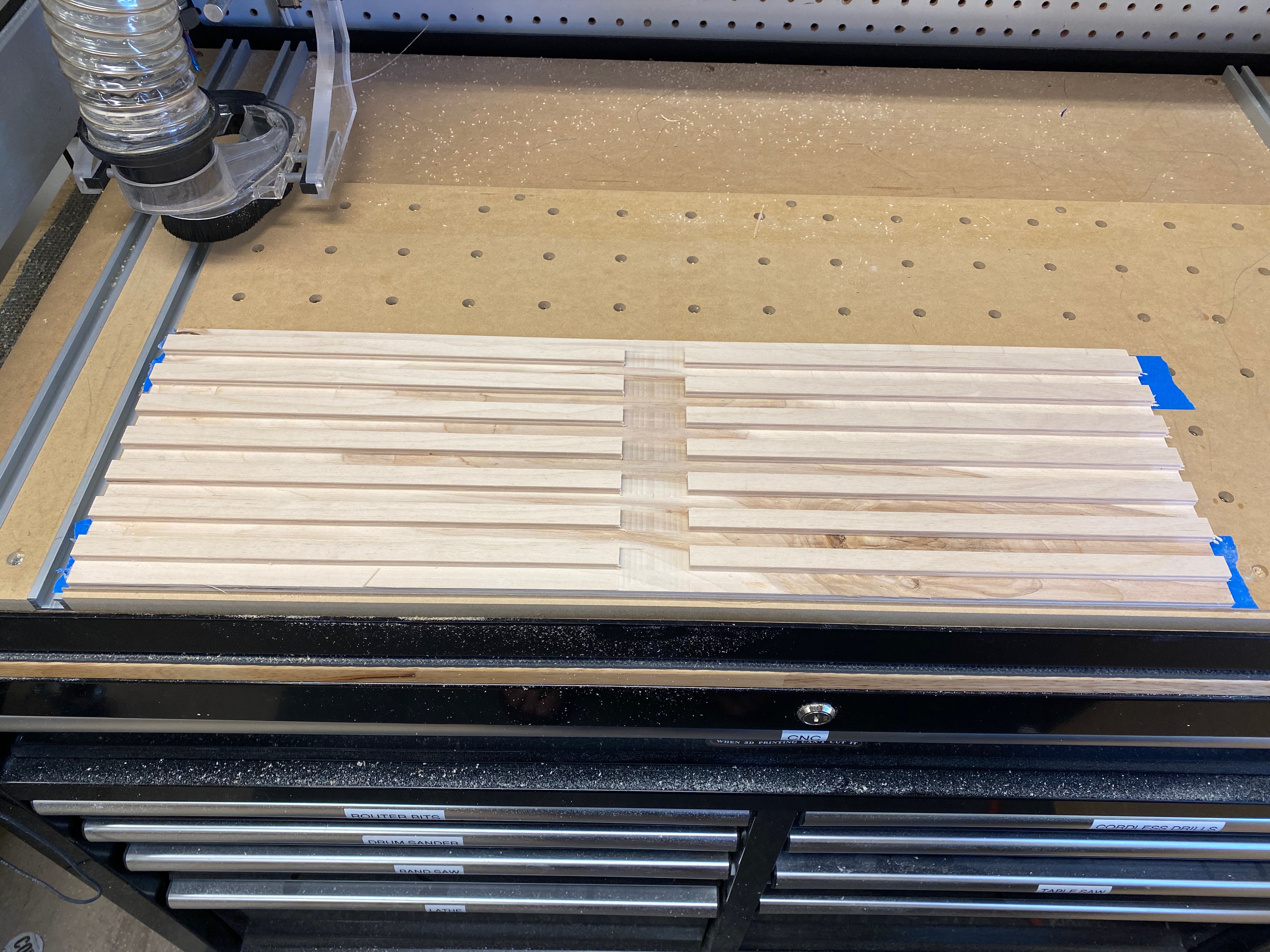
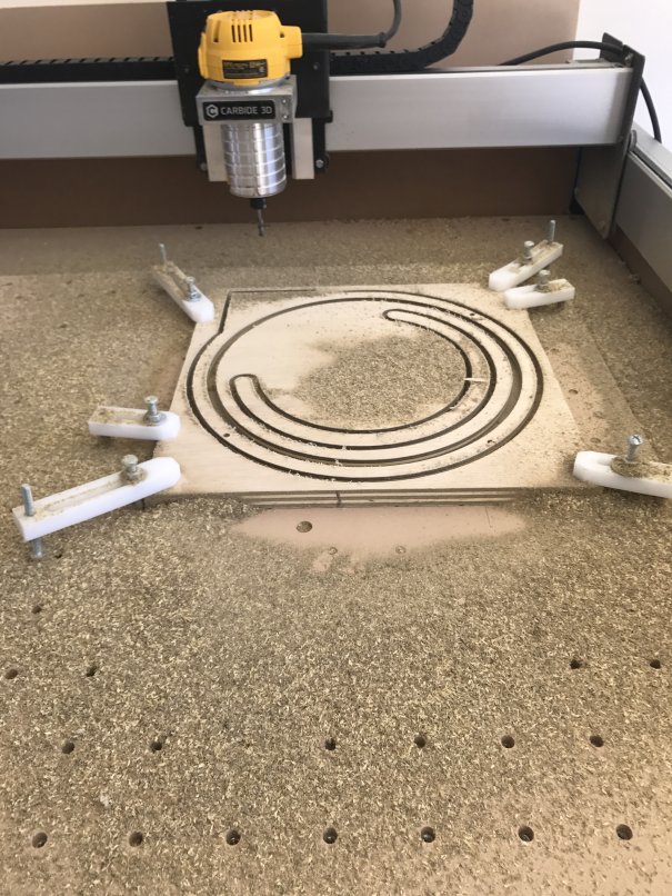
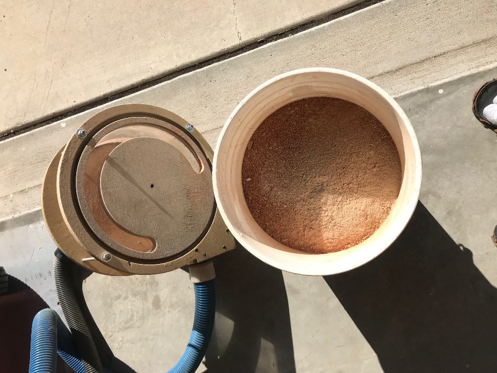
You’ll see in the pics below that cutting without a dust collector makes a real mess.


Step 1: Gather the materials
I used the following for this project:

  1. 1 - 2’ X 4’ X 3/4” ACX ply from your local purveyor, about $22 in my area. Or a similar size less expensive piece, I just happened to have the ACX on hand.
  2. 1 piece clear (If you want to see the chips being collected) acrylic sheet 7” X 36”. The design will accommodate up to 1/8” thick, but my Saturday night CAD supply store only had .093” X 20” X 36” which worked perfectly, about $18. Using something thinner and thus more flexible is a workable option.
  3. 1 – 36” X ¼”-20 all thread rod, $2. Cut 3 pieces 7.25”
  4. 6 – ¼”-20 nuts, $0.36
  5. 6 – ¼” washers $0.30
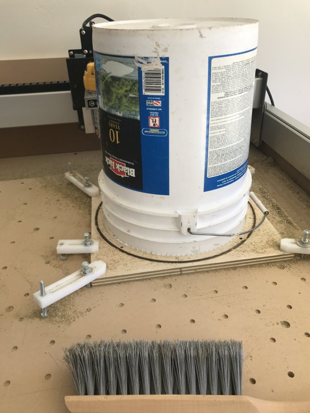
  6. 1 - 5 gallon bucket. I had a paint bucket on-hand, but a Homer bucket or similar should work. All the buckets I checked had the same diameter and lip size at the top.
  7. Here are the Carbide Create .c2d files:
  8. And here are the DXF files if you’re using a CAD program other than Carbide Create.

The Carbide Create Steps

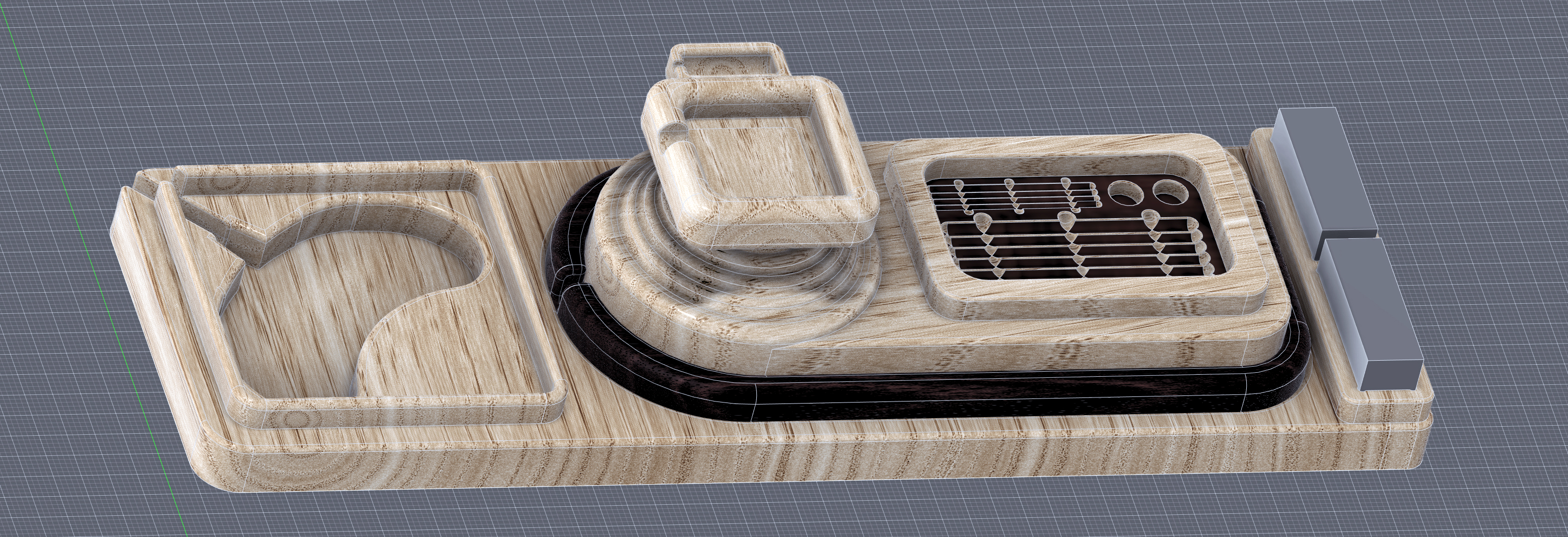
Step 2: Collector Lid

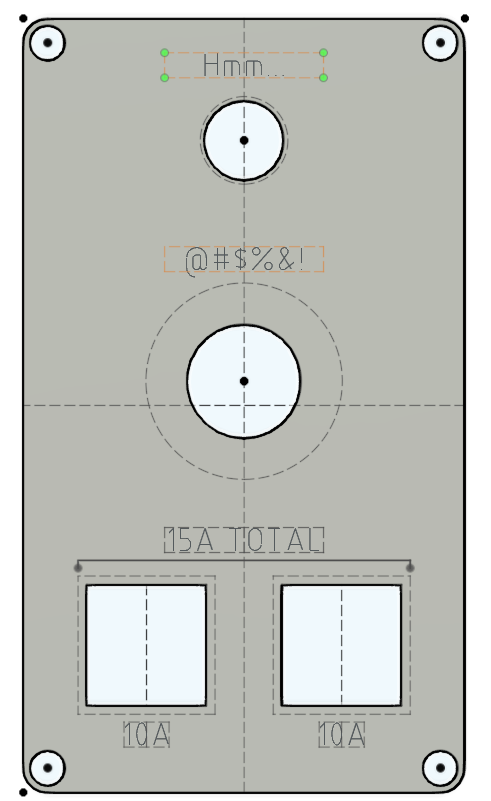
  1. Open the Dust_Separator_Lid.c2d in Carbide Create. Don’t worry about the letter ‘B’ you’ll see, I only used this as my reference to know I was working on the bottom of the top piece.
  2. Check the stock thickness from the Job Setup page. These files are set to 0.720” but most plywood varies in thickness and you should reset this to accommodate your material.
  3. In Design mode, check and confirm the width of the cuts for the inlet blocks and adjust as necessary for the material you’ll be using. For help with checking the dimensions in Carbide Create, check this video:
    https://youtu.be/QwtRf-x3vLQ
    Thank you @WillAdams for pointing me to this.
  4. Still in Design mode, check radius/ diameter for your center vacuum hole. I’m using and old house vacuum which accounts for the small size in this drawing, but you’ll want to adjust the size for your vacuum hose or the adapter that you’ve already made on your 3D printer ;-).
  5. In the Toolpath mode, check the toolpath depths for the Through Bolt Holes, Vacuum Hose Center Hole and Outside Cutout. You’ll want them a couple of thousandths less than your material thickness unless you don’t mind cutting into your wasteboard, but that what it’s there for, right? I just sanded the few thousandths that were left over from the reverse side and it turned out great.
  6. Still in Toolpath mode, disable all of the jobs except the Cylinder Wall Slot by right clicking on each and selecting ‘Disable.’
  7. Save the Gcode for the Cylinder Wall Slot cut with an appropriate name, I used ‘1 -Top Cyl Wall Slot’. Using a ‘1’ at the file name start helps me remember which job I’ll be running first at machining time. I used the Carbide Create default tool cutting values for the entire project and they worked fine. You can see these values by double-clicking each of the toolpaths to open the dialog box.
  8. Now disable the Cylinder Wall Slot and enable the remaining four toolpaths by right clicking on each. Save the Gcode with an appropriate name. I used ‘Dust Separator Lid’.
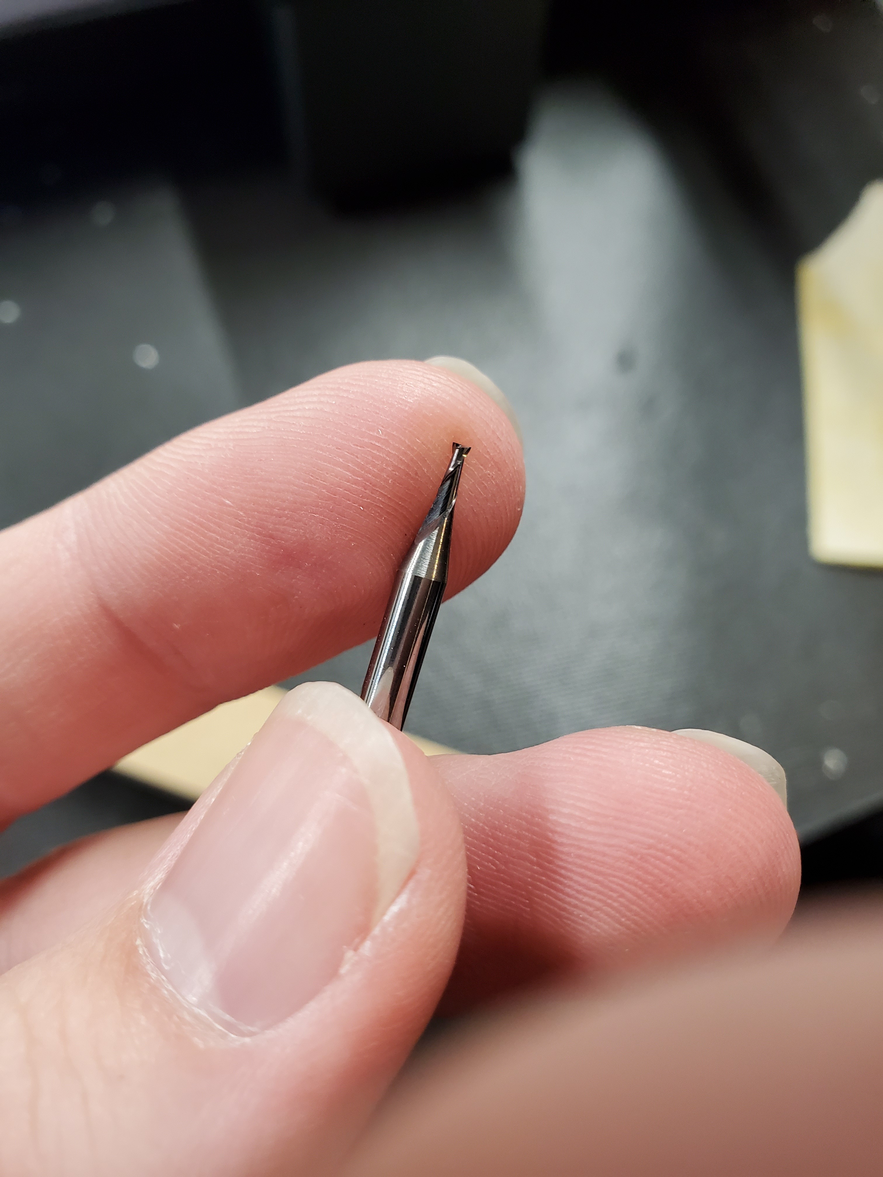
    Note: The reason for two separate jobs is a required bit change after the cylinder wall slot is cut using a 0.125 end mill. More on tool changes here: http://docs.carbide3d.com/tutorials/tool-change/

Step 3: Collector Base – Top Side

  • Open the Dust_Separator_Base_Bottom.c2d. The text “Top” is here just to verify which side of the piece is being worked on.
  • Check the stock thickness from the Job Setup page. These files are set to 0.720” but most plywood varies. Also note that the Toolpath zero point is set to the center of the piece. We’ll be using this to help with recentering when we flip the piece to machine the other side.
  • In Design mode, check and confirm the width of the cuts for the inlet blocks and adjust as necessary for the material you’ll be using. See step 2, item 3 for a refresher if needed.
  • In the Toolpath mode, check the toolpath depth for the Centering hole. You’ll want this at or a couple of thousandths less than your material thickness.
  • Still in Toolpath mode, disable all of the jobs except the Cylinder Wall Slot by right clicking on each and selecting ‘Disable.’
  • Save the Gcode for the Cylinder Wall Slot cut with an appropriate name, such as ‘Collector Base Cylinder Wall Slot’. Again, I used the Carbide Create default tool speed values for the entire project and they worked fine.
  • Now disable the Cylinder Wall Slot and enable the remaining toolpaths. Save the Gcode with an appropriate name.

Step 3A: Collector Base – Bottom Side

  • Open the Dust_Separator_Base_Top.c2d file
  • Check the stock thickness from the Job Setup page.
  • In the toolpath mode, you’ll be able to enable all f the toolpaths to create one single cut file since the same bit is used for all operations. Save the Gcode with an appropriate name.

Machining the Parts

I cut the 2’ X 4’ plywood down to 2 - 14” X 14” pieces on the table saw to make them easier to set square on the Shapeoko table. Not knowing about all of the two-sided machining tricks like doweling made this ahem, trickier for the bottom piece that required cuts to both sides.

Step 4: Lid

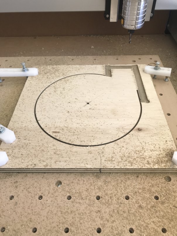
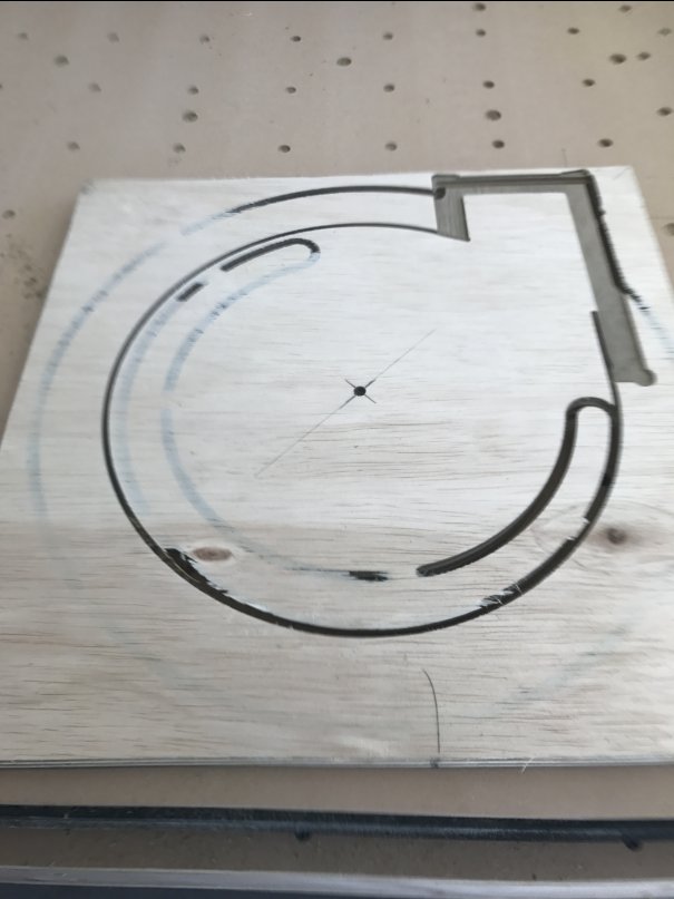
  • I started with the Collector lid since it was a single sided machining operation. To get the plywood center to match the toolpath zero point, I carefully drew a line from each corner, which turned out good enough for this project. As seen in the photo below.
  • Line the plywood edge that is closest to you along the X axis. I had previously engraved .010” lines on both the X and Y every 4” using a 90 v-bit, so this was an easy alignment.
  • To get the exact toolpath XY zero, I inserted a v-bit and centered this on the marks in step one.
  • Change to the bit used in your first toolpath and zero Z to the material surface.
  • Run the toolpaths saved in step 2 above.

Step 5: Collector Base Bottom Side

  1. For the base, which requires two sided machining, I again drew a line from each corner, on both sides, to find the material center.

  2. Repeat steps 2 and 3 from the previous step 4 to find XY zero.

  3. Change to the bit used in your first toolpath and zero Z to the material surface.

  4. Run the toolpaths created for the base bottom from step 3.


  5. Now the tricky part setting up for the second side. Leave the bit in the router and move the router clear of the work area.

  6. Flip the plywood, and place it close to the X baseline you just used.

  7. Bring the router back to the current XY zero.

  8. Carefully lower the bit moving the plywood until the bit is below the surface in the center hole cut when you ran the toolpaths on the base bottom.

  9. Make certain that the plywood edge facing you is running parallel along the X baseline, very important to get the alignment needed for the top cuts.

  10. Run the toolpath for the block recesses created in step 3.7.

  11. Change to a 1/8” end mill and run the toolpath created in step 3.5.

Step 6: The 3 Blocks

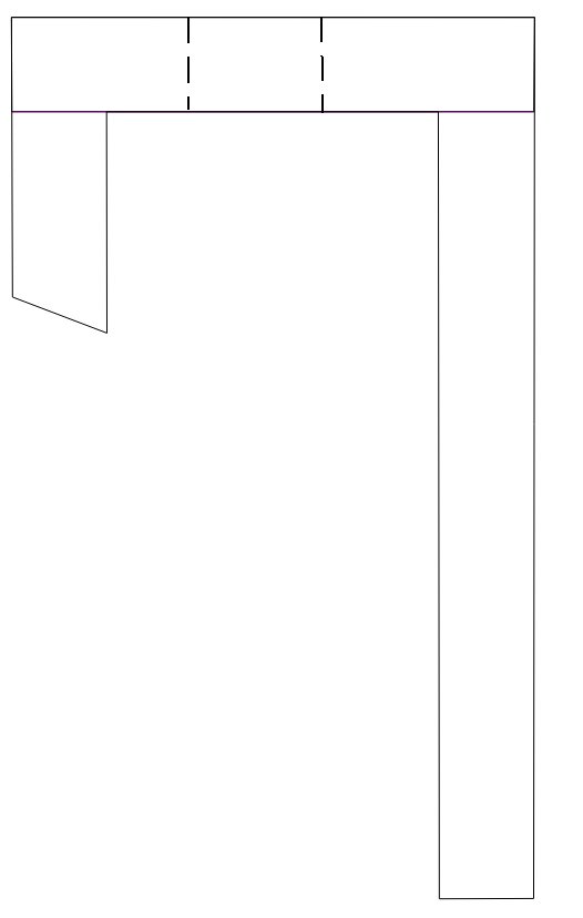
  1. I cut the three blocks from scrap left over from the above operations using a table saw. Three blocks are required, all 5.25” tall and 2”, 4” and 6” long.

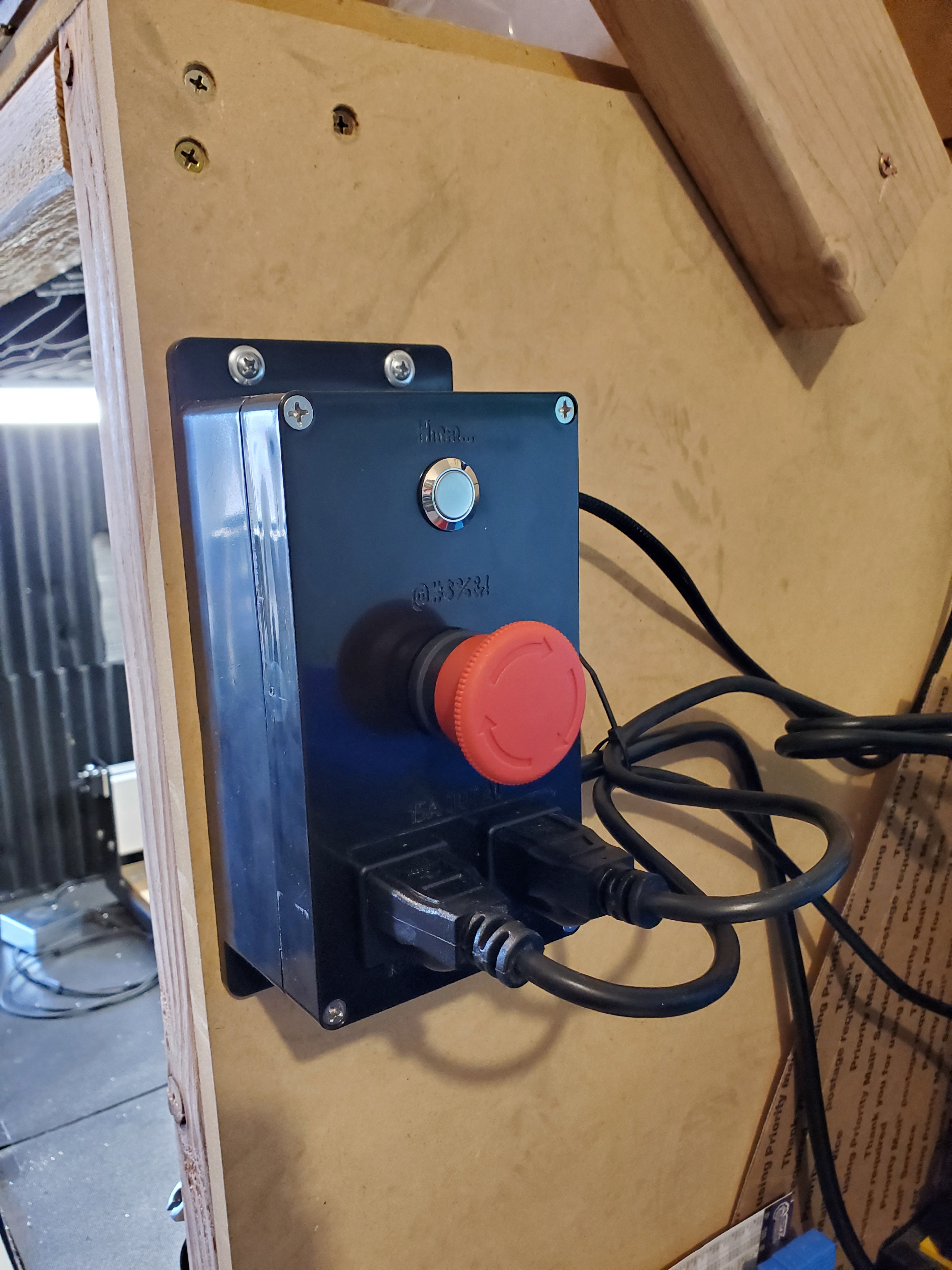
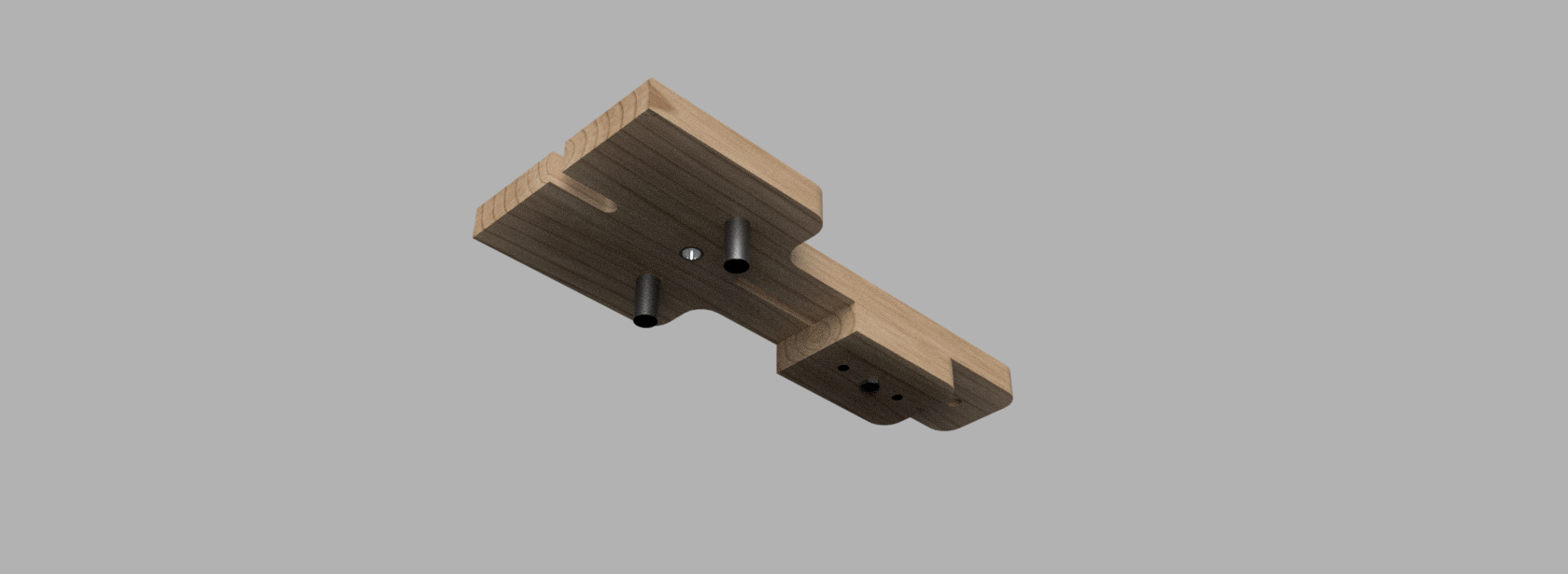
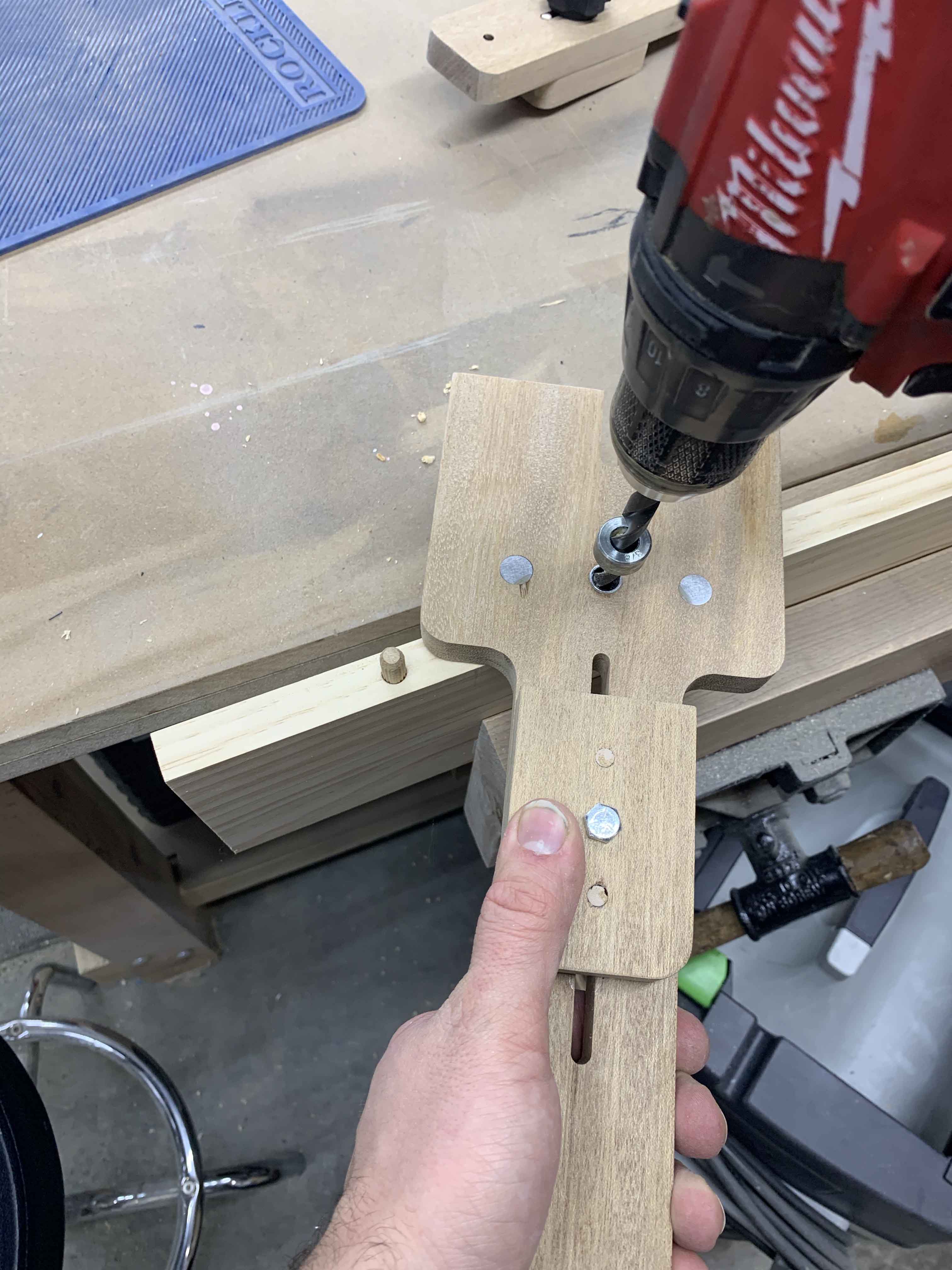
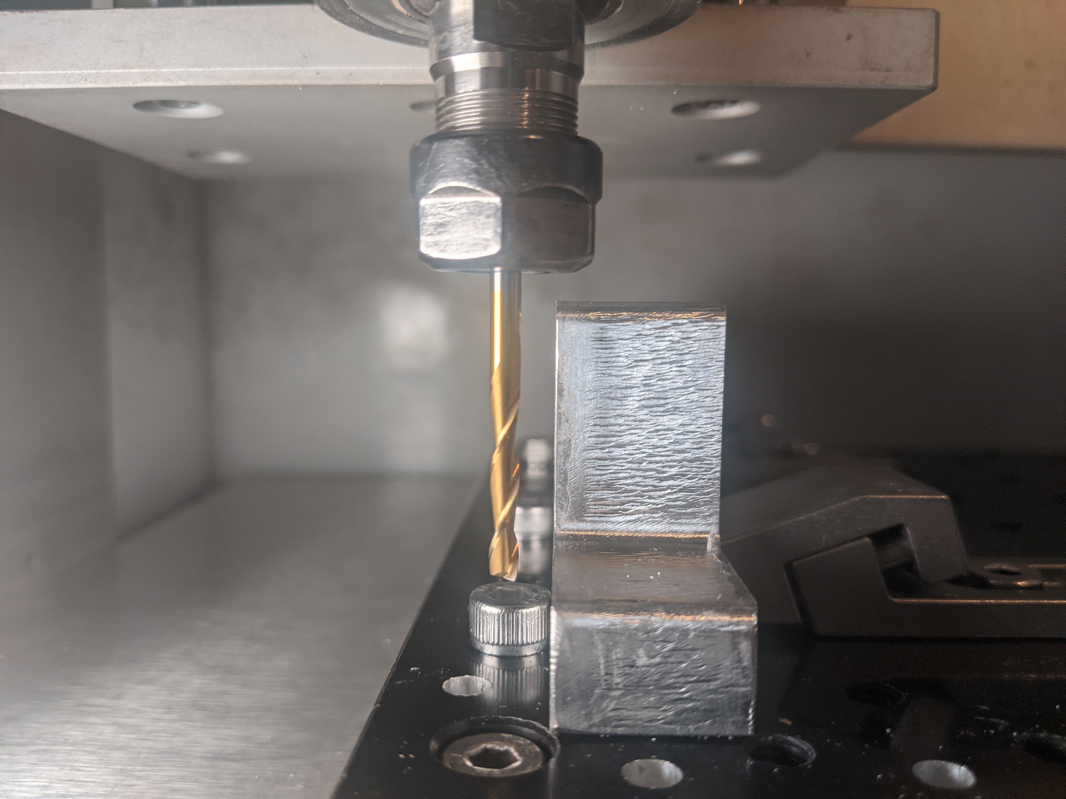
  2. Make a center point in the 2.5” X 5.25” piece and drill an inlet hole the size of the vacuum adaptor that connects to your Sweepy or other dust collector.

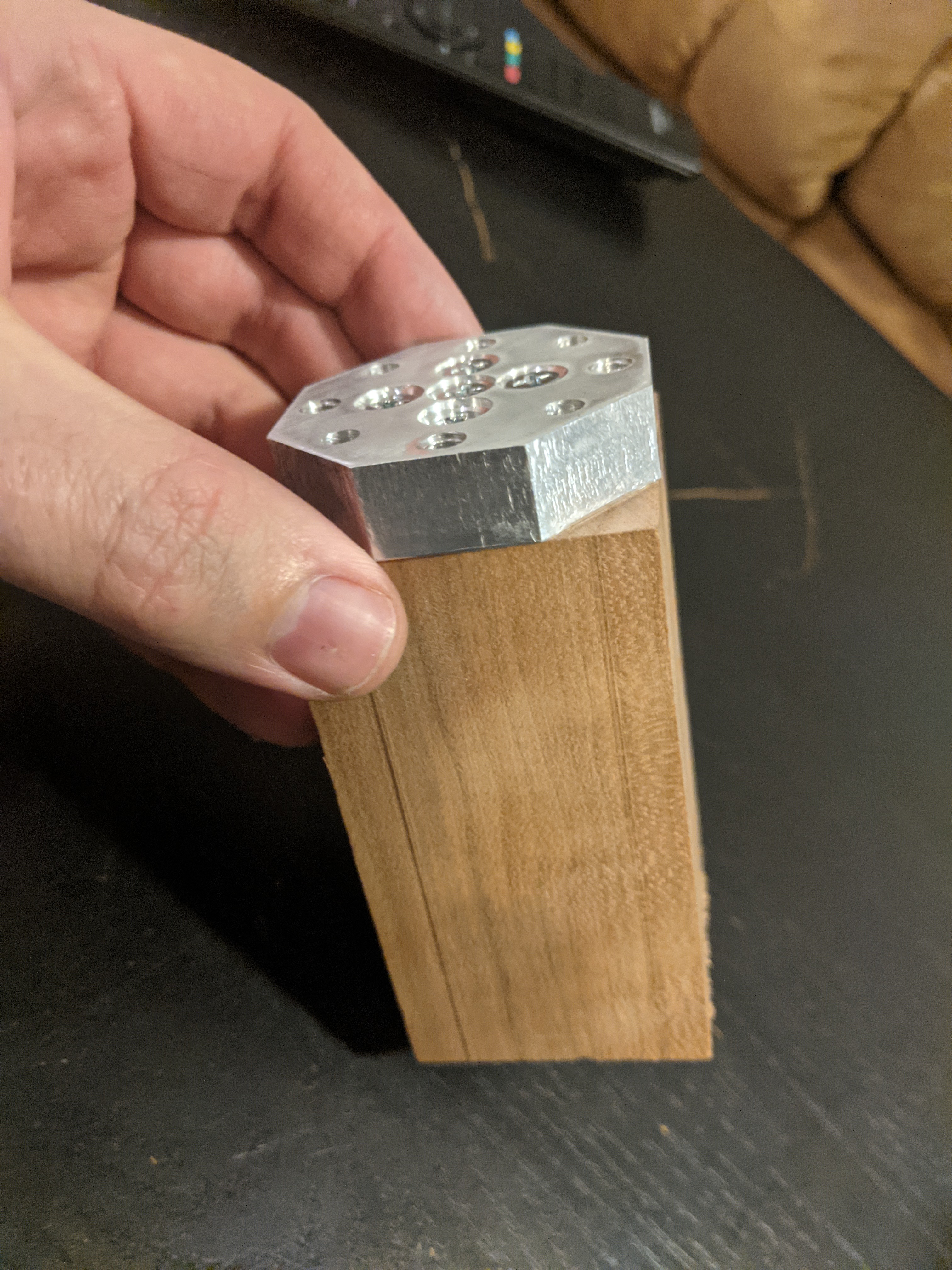
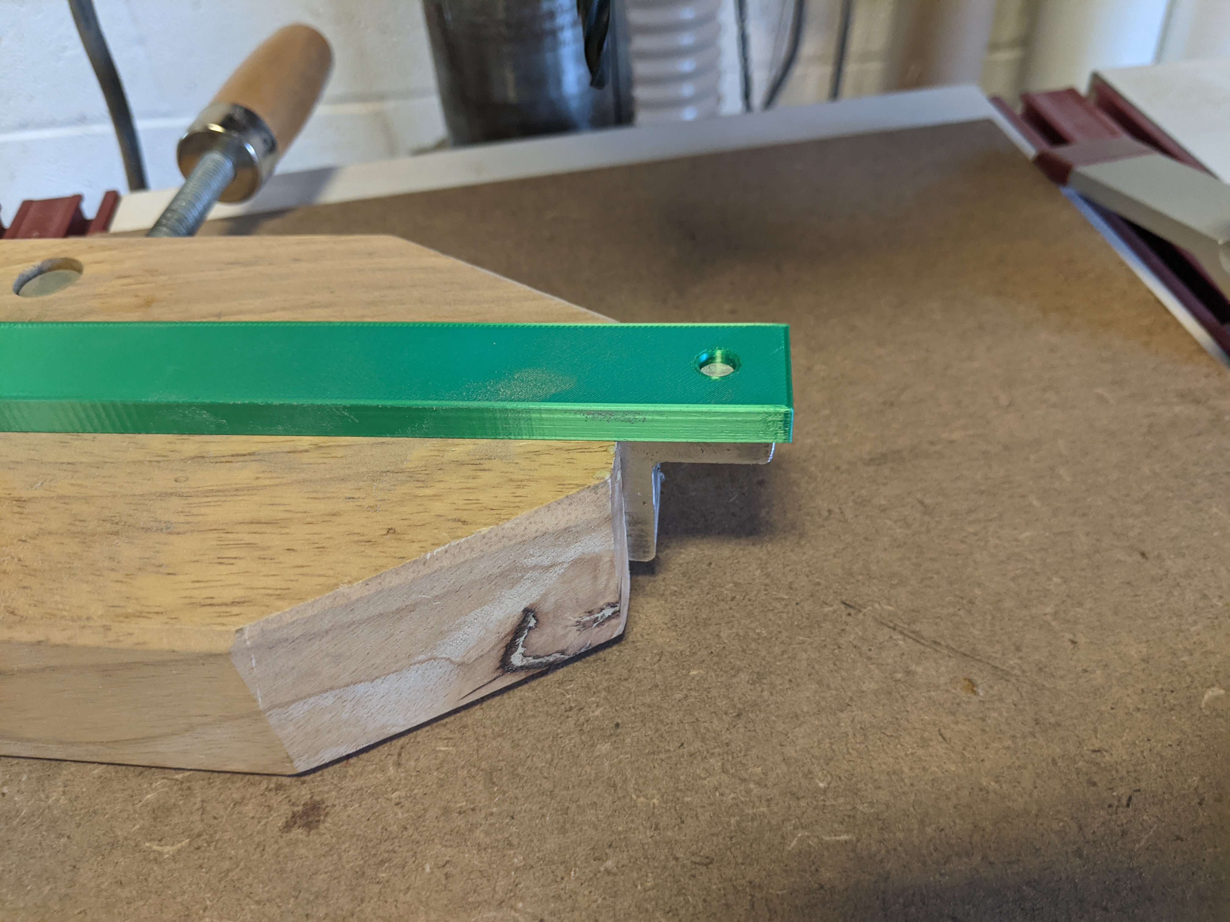
  3. The 2” X 5.25 block will need a 20 degree angle on the edge that abuts the plastic piece, which is visible in the Dust_Separator_Lid.c2d and Dust_Separtator_Base_Top.c2d files.

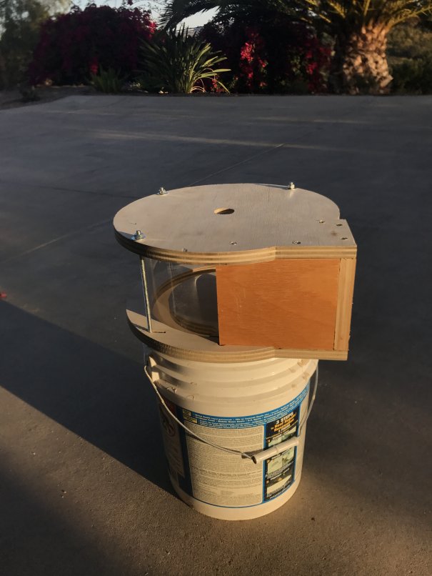
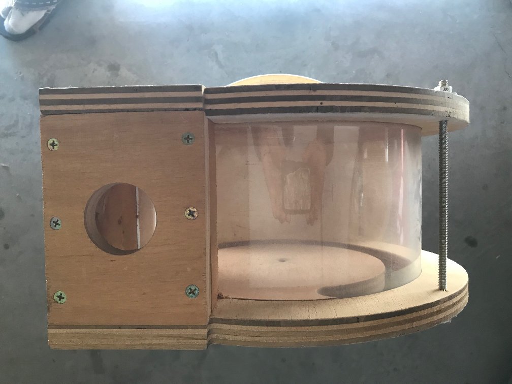
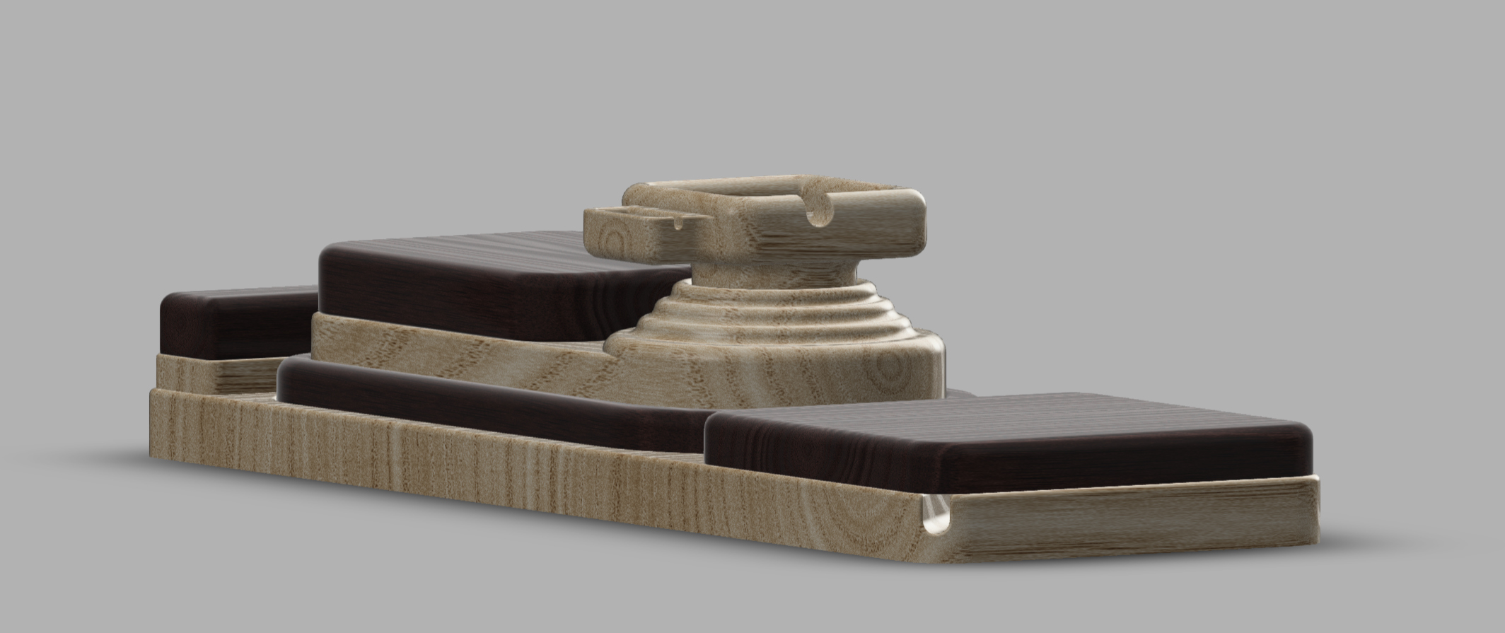
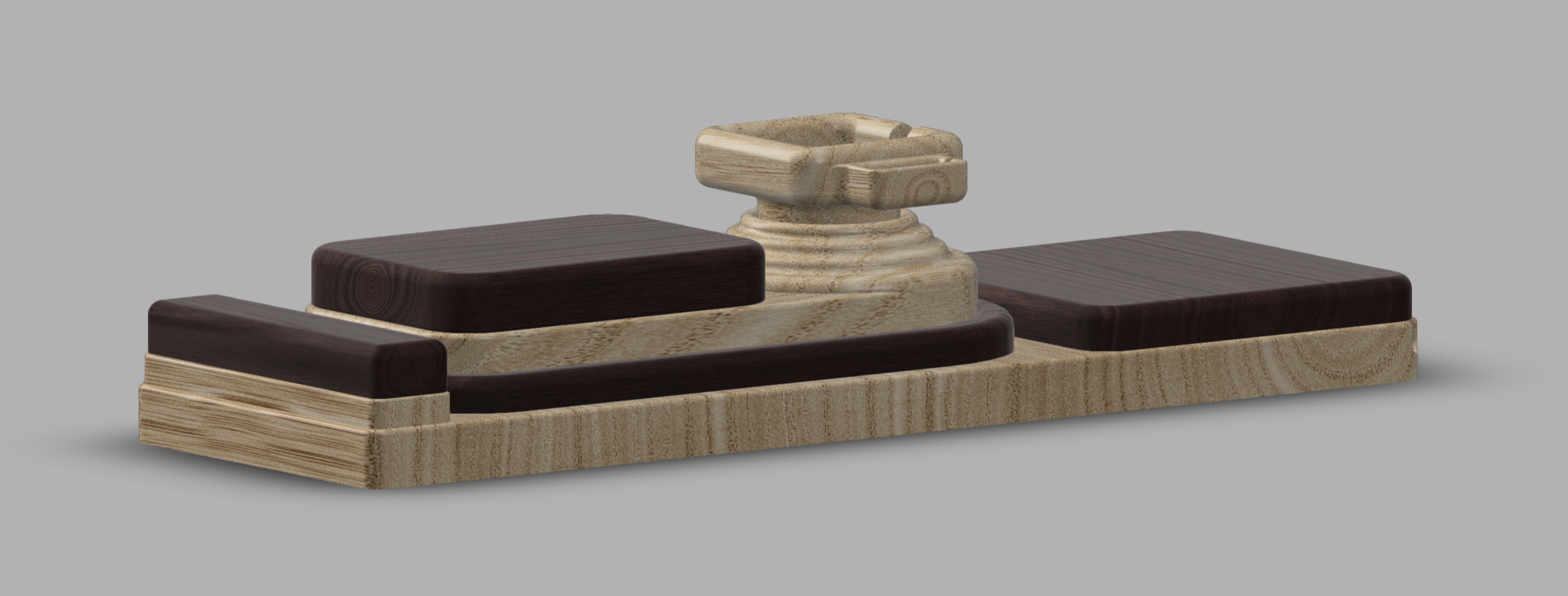
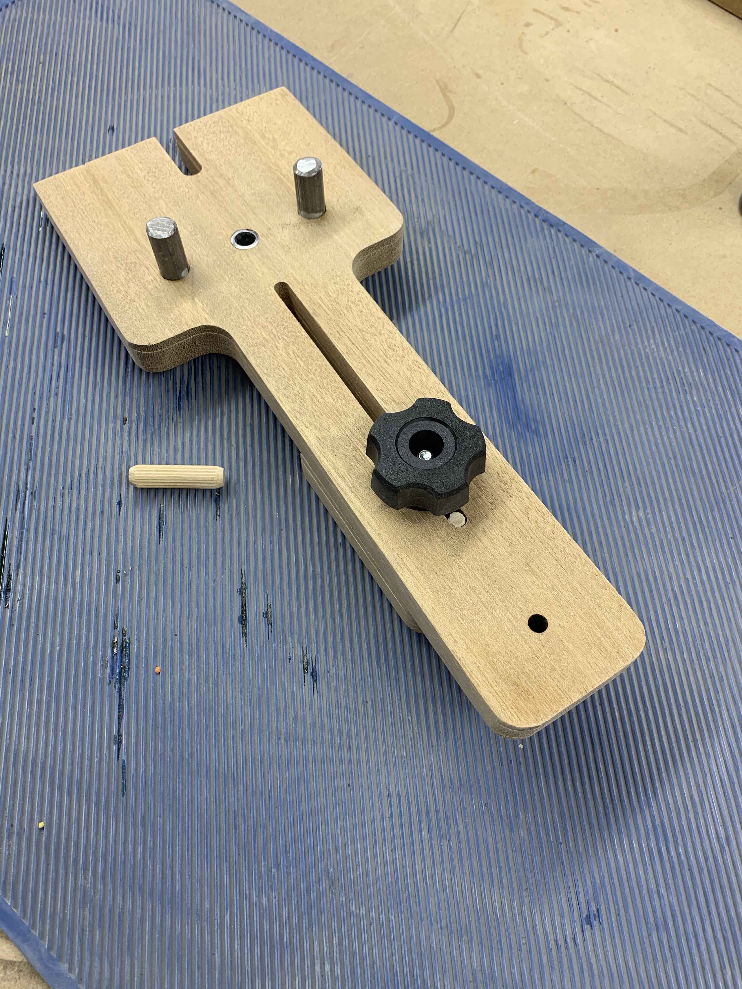
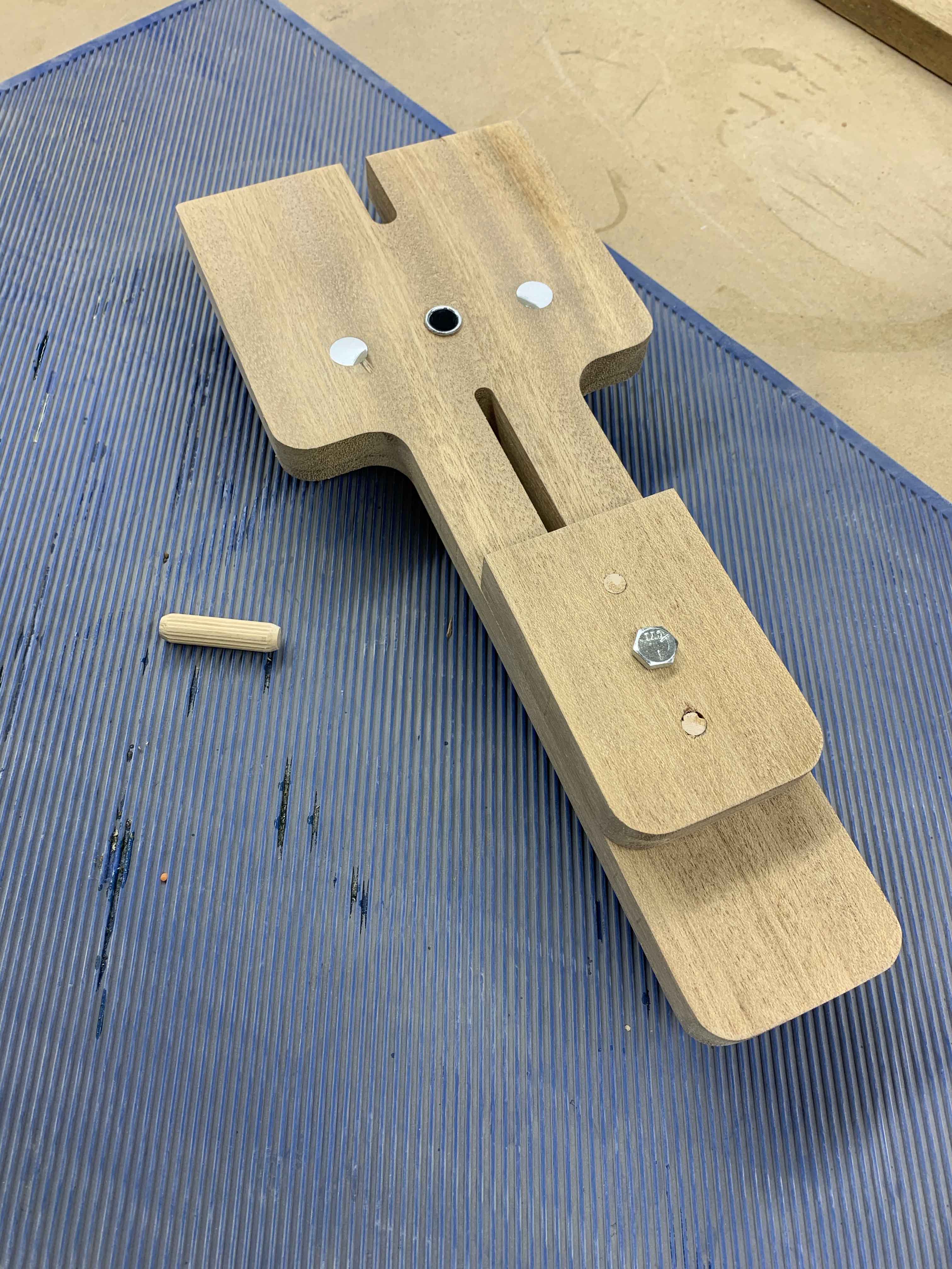
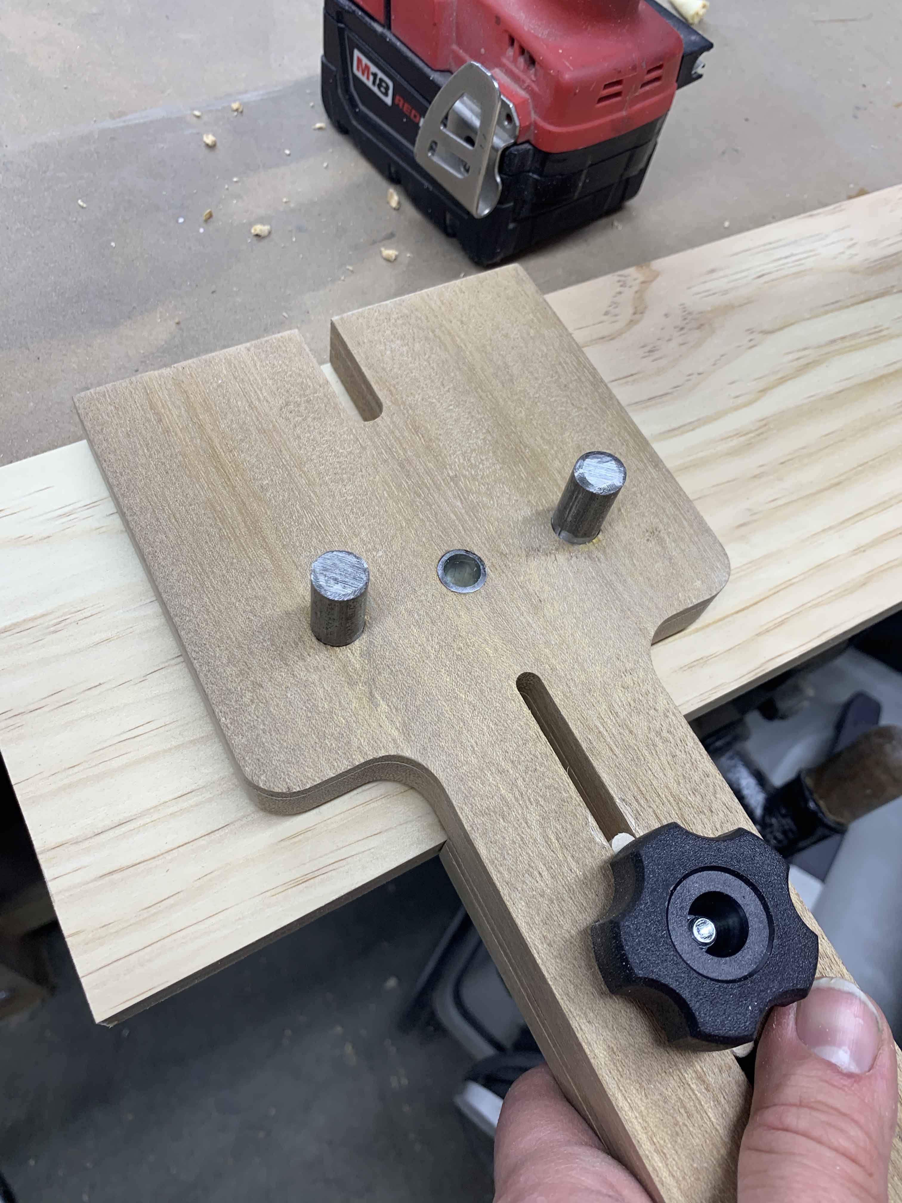
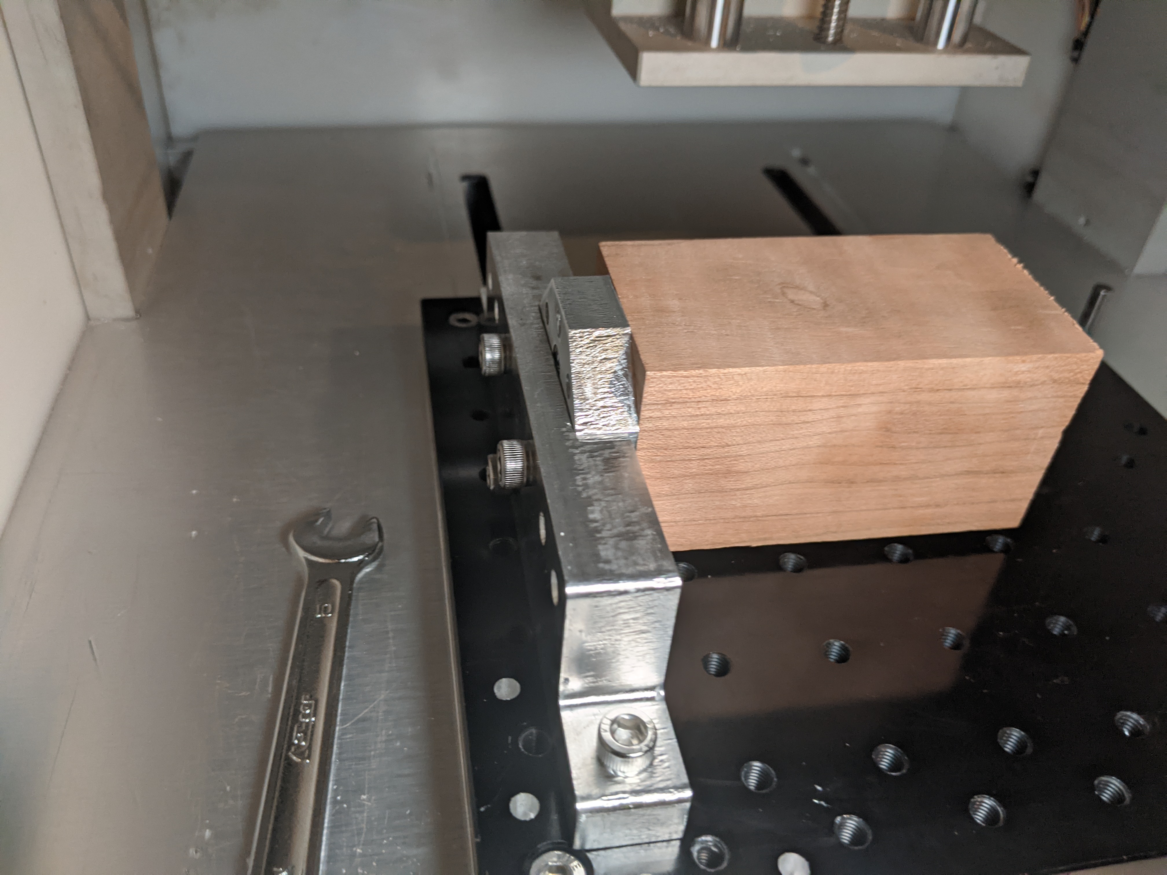
  4. Assemble the blocks as shown. I glued and screwed this together.


  5. Attach the block assembly to the top piece with screws. I didn’t use glue as I might need to replace the plastic someday.

  6. Cut the plastic 5.625” high and overcut the length. I measured just over 29” so I cut 30”

  7. Insert the plastic into the slot in the top with the blocks bending carefully. Check, mark and cut the final length.

  8. Put nuts and washers on one side of the allthread pieces, reinsert the plastic.

  9. Now trap the blocks and plastic with the bottom piece and insert the allthread pieces.

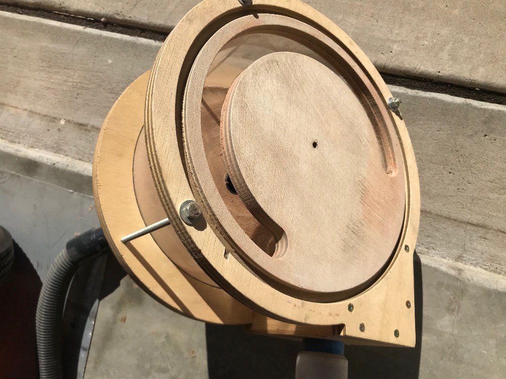
  10. Add nuts and washers to secure the assembly. I did not use glue to make disassembly easy should it ever be required. The plastic bending against the cuts it’s trapped in seals really well.


    Mistakes and Tips:

Measure the plywood that you acquire from your supplier as thicknesses can vary by several thousandths or more in some cases. This almost caught me thinking the ¾” meant, .750 which is not the case!

I fully expected to see chipping while milling the plywood and wasn’t disappointed. You can limit this chipping with a down cut bit (which I didn’t know existed then) but I was after function rather than form.

Setting the plastic in the sun or other warm spot would make it much easier to bend to the cutout radius.

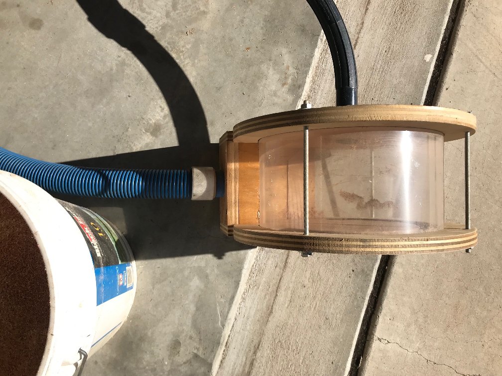
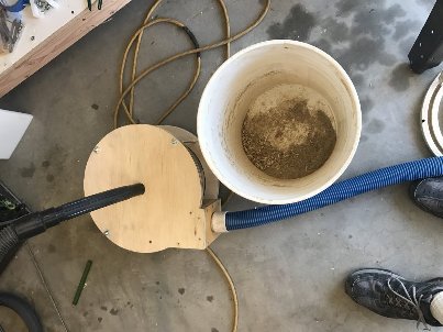
This works really well even though it’s got a recycled house vacuum power:


Function_Test_01

Carbide 3D Files
Dust_Separator_Base_Top.c2d (394.3 KB) Dust_Separator_Lid.c2d (682.6 KB) Dust_Separator_Base_Bottom.c2d (305.4 KB)

And finally, the CutRocket link:

11 Likes

For your consideration,
A seven piece tool and probe holder created with Fusion 360 and carved with my XXL Shapeoko. The tool tray insert is black walnut, surrounded with red oak, nested with a sapele base and lid. The probe holder is a two sided operation cut from two inch thick red oak, all finished in walnut oil. I had originally planned to expand this set to hold two 123 blocks and a USB Sega controller, but changed plans after learning about and purchasing the awesome keypads that @i3oilermaker makes, and will revisit and re-design the rest of the set at some point in the near future.

This piece took a considerable amount of time to design and carve, I used 1/4 and 1/8 down-cut 2 flute flat end mills, 1/4, 1/8 and 1/16 ball mills for the beveling and went down to .8 mm for the small tool slots. The 2 sided operation used four 1/4 stainless pins for locating a tabbed frame on top of MDF. Everything is straight off the machine, with no finishing work needed, though there is a slight seam on the probe holder I missed due to a power outage, that I need to address with some sand paper.

Below is the Fusion web link for the downloadable full set including the USB Sega controller holder. If anyone wants to make this, just let me know I will tailor make tool-paths for your setup.

Fusion Link


Cut Rocket

10 Likes

I have been wanting to do this project for a while, I am typically busy with production type work to do special project. This contest spurred me to spend some time this weekend on this. I wanted a dowel jig and didn’t like the price and or quality of the store bought dowel jigs. I have seen people make similar jigs as this by hand but haven’t seen one on the CNC.

I created the file in Fusion 360 and was able to try a couple new commands I don’t usually use. Slot cutting, this is an interesting command that using ramping to make slot cutting a little more effective. Rapid out drilling, on the half inch holes it was very effective and clean boring them out in a circular motion.

Regarding the jig, I made it from a scrap piece of beech wood I had laying around and just had to buy the knob, bolt and bushing at the local hardware store for a few dollars. I had the half inch steel rod and dowels, they could be aluminum as well if that’s what you had and could varying in size while still being effective.

The jig is used to center dowels holes on the edge of any width board within reason and has a sliding stop for face of boards.

I uploaded this to Cut Rocket for anyone interested. I would say the feeds are a little aggressive for the beech wood but a softer wood would be fine. I adjusted them to 80% when milling for them to seem optimal.

Setup Sheet for Program Dowel Jig.pdf (114.4 KB)

10 Likes

It (mostly) worked! My single flute endmill broke a while back and I’ve been too cheap to replace it. Please excuse the wall finish on these parts.
My machinist buddy was out of town this week. I’m usually able to bribe him with food/booze to do quick things for me, like tapping holes and boring out odd things, so I had to do a bunch of stuff on my own. Which with limited tool sets at home, some things were hardly ideal.
Anyways, here’s finished project:

How it works:
I take a stock no larger than 55mm (or 50mm if running 8 sides) and put it on this plate with wood screws:


Then I mount that plate to the jig and machine away.

One of the bigger challenges that I kept procrastinating on solving was milling the holes to secure it to threaded table. Seen here I didn’t have much clearance:


I did 3d print a jig and made the hole at the makerspace near me:

Also had a fun time playing around with better facing operations on the nomad. 1/4 inch endmill taking .025mm passes, and also doing the facing operation in fusion instead of creating a block and contour operation in carbide create like I normally do produced WAY better results. Thanks to @wmoy for that.


It’s too late for me to run swole Pikachu, so I’ll run it tomorrow, but fairly certain this will all work. Not too concerned with deflection. I have a video on my instagram (last vid of my most recent post) where I’m pushing and pulling on the stock. Table moves with the motions.
Center point of the rapid position should be the Y coordinate. The right most portion of the stock should be the X, and then 30mm up from the threaded table should be the center for Z (plate is 25mm wide, 5mm lip).

Here’s the fusion link (still need to modify a few things): https://a360.co/36iQKjL
Cutrocket: https://cutrocket.com/p/5fc46f3a49535/
Toolpaths weren’t tried, just drew up the shape.

7 Likes

Over the past couple months I have been cleaning up my shop and I created a French cleat system to store my tools and hardware using my Shapeoko 3 XXL. For reference a French cleat system is a system that allows you to mount objects to your wall and easily move and arrange them. I thought it would be nice to have a generic French cleat bracket where I could make custom 2x4 inserts for my tools. I came up with two designs at flat top and a 45 deg top. All of the brackets are tabbed and slotted to allow for easy alignment and assemble without clamps.

This allows me to cut out a bunch of generic brackets and just make custom 2x4 inserts for whatever tool I would like to mount to the wall. This has worked out great since I will create a new custom insert every couple weeks. So far I have come up with 8 custom inserts to mount my tools and a custom bracket for my jack planes.

Shapeoko end mills and hold on

Pilers, Screwdrivers, Chisels

Bit drivers and measuring tools

I also wanted a way to organize my bolt box of misery. I came up with a small box with a French cleat attached to the back. This has worked out great. I have finally been able to find the correct hardware without searching for hours

Bolt boxes and ratchet set

Lesson Learned: All of my brackets have been made out of 0.25 mdf. When cutting the MDF I found that using a down cutting endmill makes for much better cut quality. The first couple boxes I used up cutting bits and had lots of fuzzy edges. Once I switch to a down cutting endmill the cut quality was much better

Overall i have been very happy with this project. it is great building it over time and being to move my tool holders around to optimize the organization. Just a great system that grows with you over time

Attached is a step file with all my French Cleat designs:french_cleat_main_asm.zip (293.6 KB)

Cut Rocket link: https://cutrocket.com/p/5fc46108153ea/

19 Likes

Time is up, thank you all for participating !
Vote is now open here

2 Likes

I really like this idea Josh, thank you for the files and great job!

Well done all! Was a little worried this would devolve into a “how I modded my machine” contest but nothing of the sort. Big salute to @Julien and the C3D crew for another interesting contest!

5 Likes