Community challenge #16: Lego-style (closed)

Look at that, it’s the anniversary of community challenges, we have been at it for more than a year now. I hope you guys and gals enjoyed it so far, we have seen some pretty incredible entries!

As we head towards 2021, the theme for challenge #16 is: Make something Lego-style.

It can be anything from individual bricks (minuscule ones made on your Nomad or gigantic ones made on your XXL?), to objects assembled from bricks you would mill, to a 2.5D carve of a Lego model (two-sided Lego Millenium Falcon anyone?), to minifigures, to anything else as long as it has a distinctive “Lego” look and feel.

Side note: I use the term “Lego” so that we’re all on the same page, I’m well aware it’s a trademark, please don’t call the lawyers.

The CAD will mostly be a bunch of squares and circles, so hopefully everyone can participate (I’m looking at you, newbies!).

Rules for this 16th challenge:

  • submit your entry in this thread:
  • you can post multiple entries if you want.
  • the project must made on a Shapeoko or Nomad.
  • you must include pics of the finished piece
  • you must include the design file
  • tell us about your mistakes, tips and tricks, etc…
  • posting your project to CutRocket will get you a +2 bonus on the vote tally.

:warning: NEW RULE :warning: : to both spice things up for our usual suspects and give everyone a chance to win, I’m introducing a penalty system for previous winners. For each previous win you had, I will apply a small penalty to the final number of votes:

  • -2 points for each time you won first place in the past
  • -1 point for each time you won second place or jury’s prize in the past.

Timeline:

  • Deadline is set to Jan 3rd 2021, midnight PST

  • there will then be 7 days for voting.

    • voting will be open to legit community members only, and the jury reserves the right to remove votes from “outsiders”, and will also break any tie.
  • First place: BitRunner + BitZero v2 + workholding kit

  • Second place: BitRunner+ BitZero v2

image

  • Jury’s prize: BitZero v2

image

You will also join the Carbide3D swag club:

image

Now go unleash your inner kid’s creativity!

18 Likes

While I make many things of Lego bricks (desk accessories (including a tablet stand w/ stylus holder), archery spine testing and fletching jig, jigs and fixtures for workholding when doing woodworking…) I’ve always used actual Lego bricks, so can’t directly provide anything to get folks started on this beyond some resources:

A video:

CAD tools:

Similar building toys/tools which may serve as inspiration:

8 Likes

A handicap system, BRILLIANT! We are an incredibly fortunate community to have such awesome moderators, thank you for making/keeping it awesome!

6 Likes

As one who would enter a few votes behind, I completely agree. This is a way to encourage the less experienced while forcing the others to challenge themselves to come up with new ideas. I wish I had more time for these contests, and I like the idea that when I do I’ll have to put a little extra into it.
Great idea! I can’t wait to see these entries start rolling in.

7 Likes

Me, sweat beading up on my forehead, checking email again to see if my Pro has shipped yet.

6 Likes

This is a cool challenge!

4 Likes

Use that energy to get drawing and designing!

When I can’t actually be cutting on my machines I draw and work on things such as:

https://willadams.gitbook.io/design-into-3d/3d-project

6 Likes

Will, I hope you’ll be flattered to know I’ve already read and bookmarked that article, and your posts here have given me loads of inspiration! And yes, I have a bunch of designs and ideas ready to go, but reading about this challenge (and the prizes, tbh) made it really hard to sleep last night.

7 Likes

I also think this is a great idea, it will give a better chance for new talent to win, and also allow past winners to compete without guilt over discouraging the new machinists.
I am at -7! -'Tis but a scratch… lol

11 Likes

hello everyone.
I am happy to present you a small project that I realized at the end of August, September.
and this challenge is totally corresponding to it :wink: thanks julien


I found a 3d lego on thingiverse in stl format.
I scaled it to a scale that suited me, and I separated the parts to load them in fusion 360, to make my machining files.

the head was the first piece made. you can see that the finish is not great, there is some finishing to do… I had made several toolpaths in fusion 360 (in parallel x and y), I ended up realizing that “adaptive” toolpaths. the finish was much better :wink:

Except the “legs”, all the parts were made in 3d, so by flipping, in two parts. (the holes of the axes are not on my files… made separately)
I didn’t have any machining problems.
But I think I can optimize my settings even more to save machining time. the precision is there :wink: the result is really nice.

since the beginning of 2020, I’ve only improved my shapeoko; by upgrading it to xxl, by buying the bitrunner, Z probe, the new hdz this summer and by making a table with storage, electricity and various switches, and a touch screen. i’m happy with my installation.
this project and the reflection of my new machine. :blush:

i can’t wait to see the new projects of this challenge which will certainly be crazier than a lego.

bras recto.nc (2.7 MB) bras verso.nc (1.4 MB) buste.nc (267.6 KB) trou sous buste.nc (34.0 KB) jambe droite.nc (605.8 KB) jambe gauche.nc (602.4 KB)liaison buste dessous 2p.nc (560.7 KB) liaison buste dessus.nc (415.2 KB) usinage main recto.nc (1.1 MB) usinage verso main.nc (423.3 KB) dessous tete lego.nc (1.3 MB) dessus tete lego.nc (1.0 MB)

29 Likes

This looks fantastic! Way to kickstart the challenge.

I downloaded a Fusion360 design file for that minifigure yesterday with the intent to play along, and now I definitely want to make one, challenge or not.

What wood types did you use ?

Also can you please include the actual design file (zipped f3d I guess unless you can still share a public link from your F360 version)

5 Likes

I can’t wait to see yours @julien.

cutrocket

I made two figurines (lego), both have the head and hands in “buis” in french, the legs, arms and connecting piece in cherry wood. ( the veining and the color is different from cherry tree)

and the difference between the two figures, one has the bust in cherry tree, the other in oak.

liaison.zip (305.8 KB)
main verso.zip (332.2 KB) mains recto.zip (670.7 KB)
dessous tete lego.zip (608.5 KB) dessus tete lego.zip (389.9 KB)
jambe droite.zip (269.8 KB) jambe gauche.zip (298.1 KB)
buste.zip (215.6 KB) trou sous buste.zip (145.1 KB)
bras recto 1.zip (1.4 MB) bras verso 2.zip (815.7 KB)

5 Likes

@Bwood34 you can post fusion files in cutrocket, check this one out: https://cutrocket.com/p/5f7e3118f348e/
And way to get the challenge going, the minifig looks awesome!

4 Likes

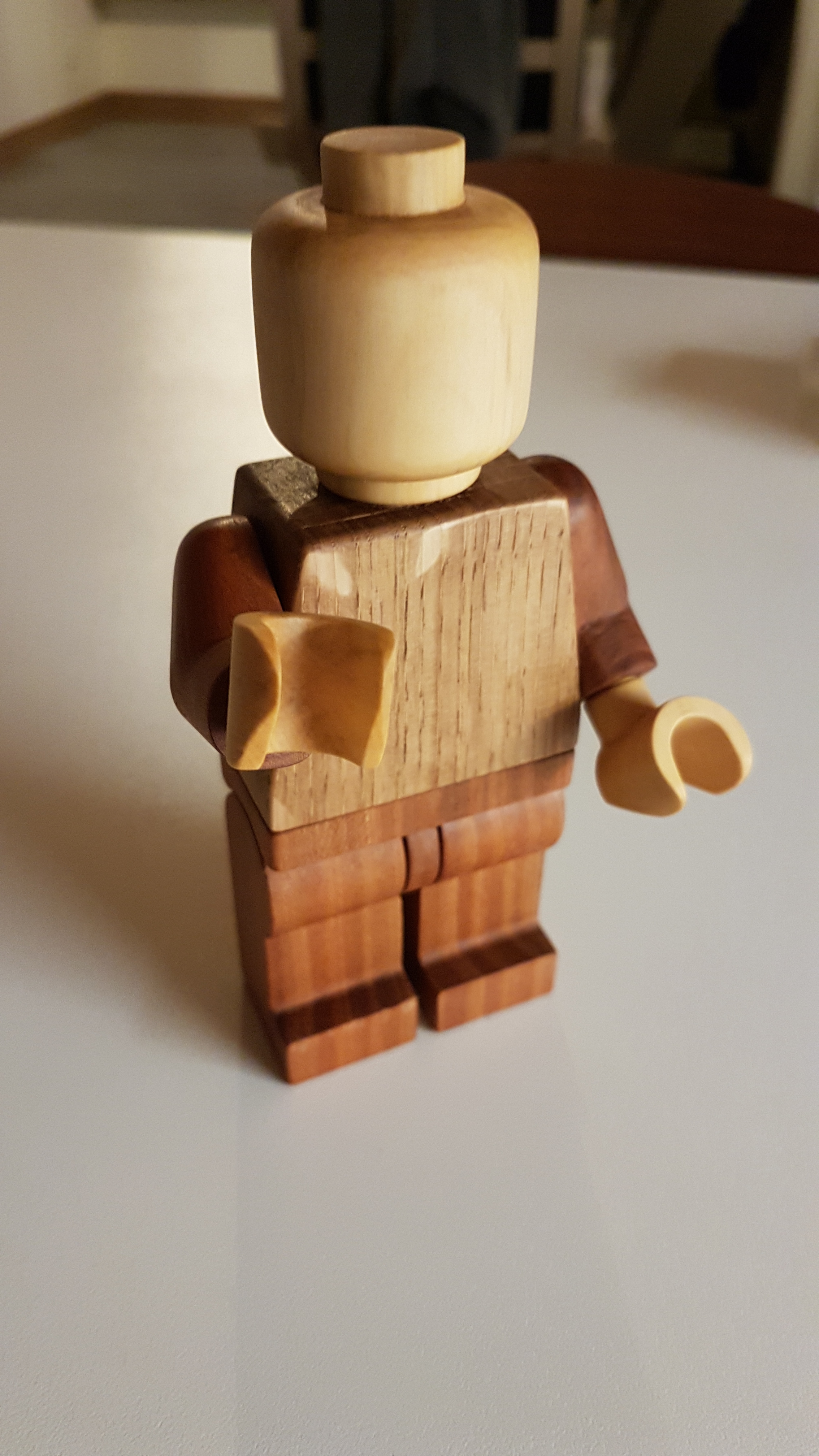
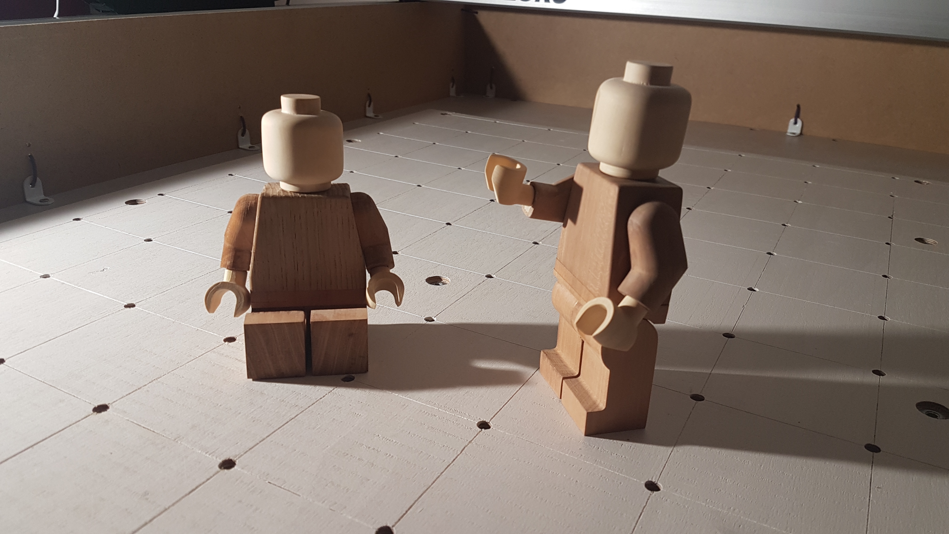
Lego “Dovetail” joint for a lego table. I just finished the test prototype, and hope to finish the whole table by the end of christmas break:

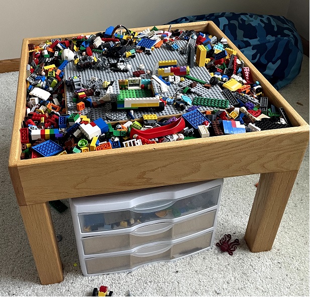
The end goal is to recreate this table I made 5 years ago with better joints:

My inspiration was a NOEL joint that Lee Valley had posted on their website that looked like it would work great with CNC
https://www.leevalley.com/en-us/discover/woodworking/2020/december/how-to-make-a-noel-dovetail-joint

My process:
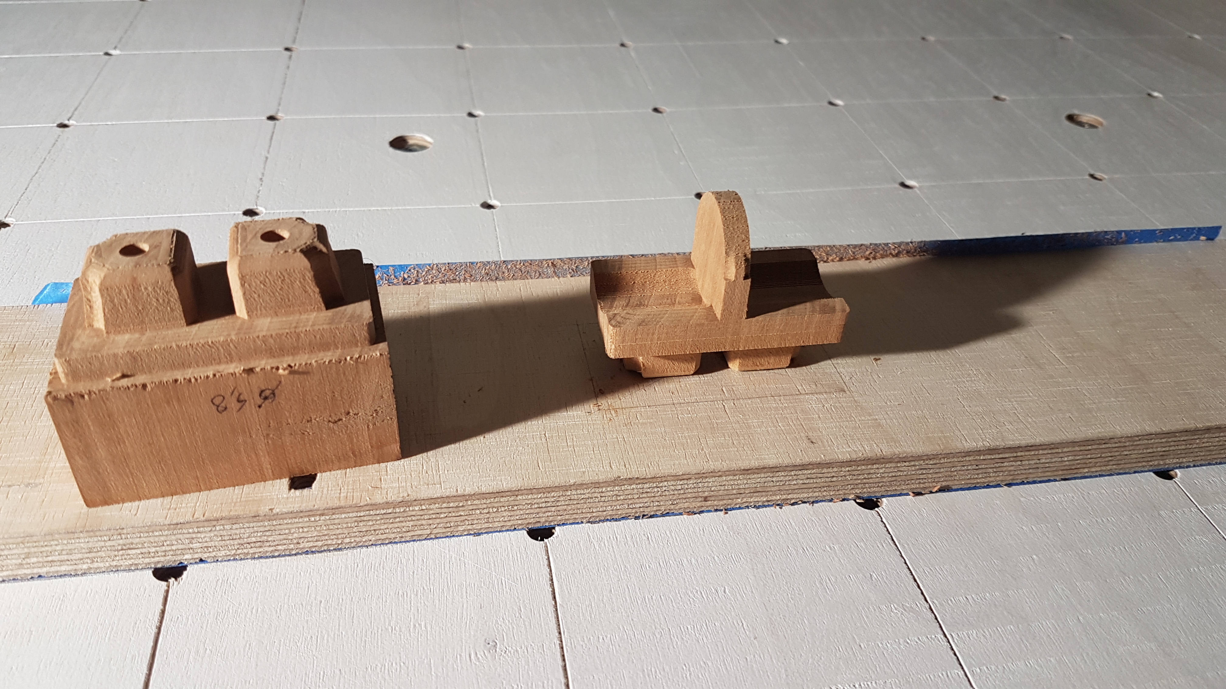
I used the Arial Black font to create blocky text that fit the area. I then converted the text into vectors and adjusted the text so that a 1/8 end mill can fit into all of the areas with the letter G being the most difficult. One trick I used was a created a circle with same diameter as the bit and moved that around manually to check spacing and adjust vectors. I created two tool paths, one that routed out the interior of the letters and one that routed around the letters. I kept simulating until when I ran both tool paths there was no wood shown in the end result.

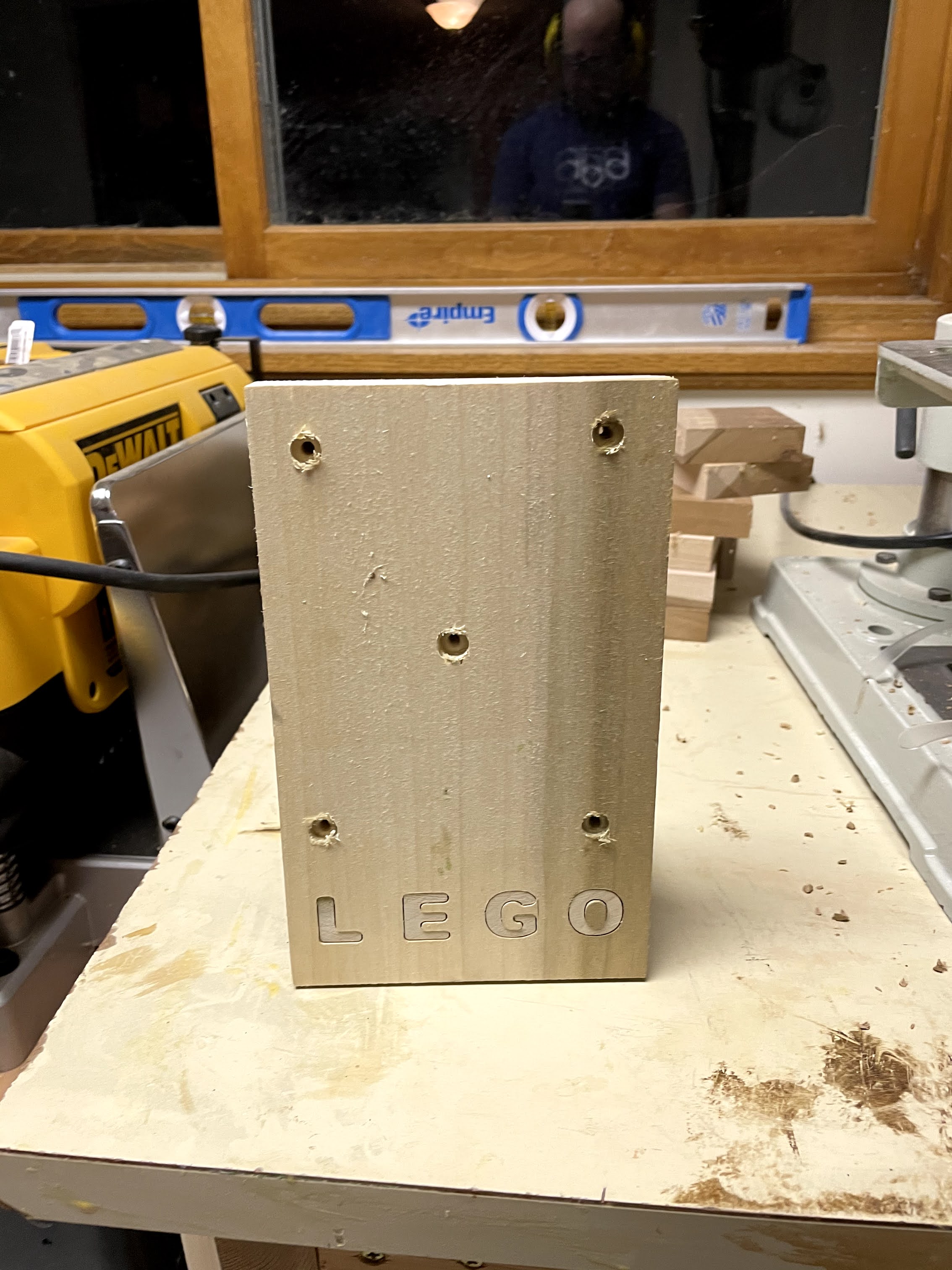
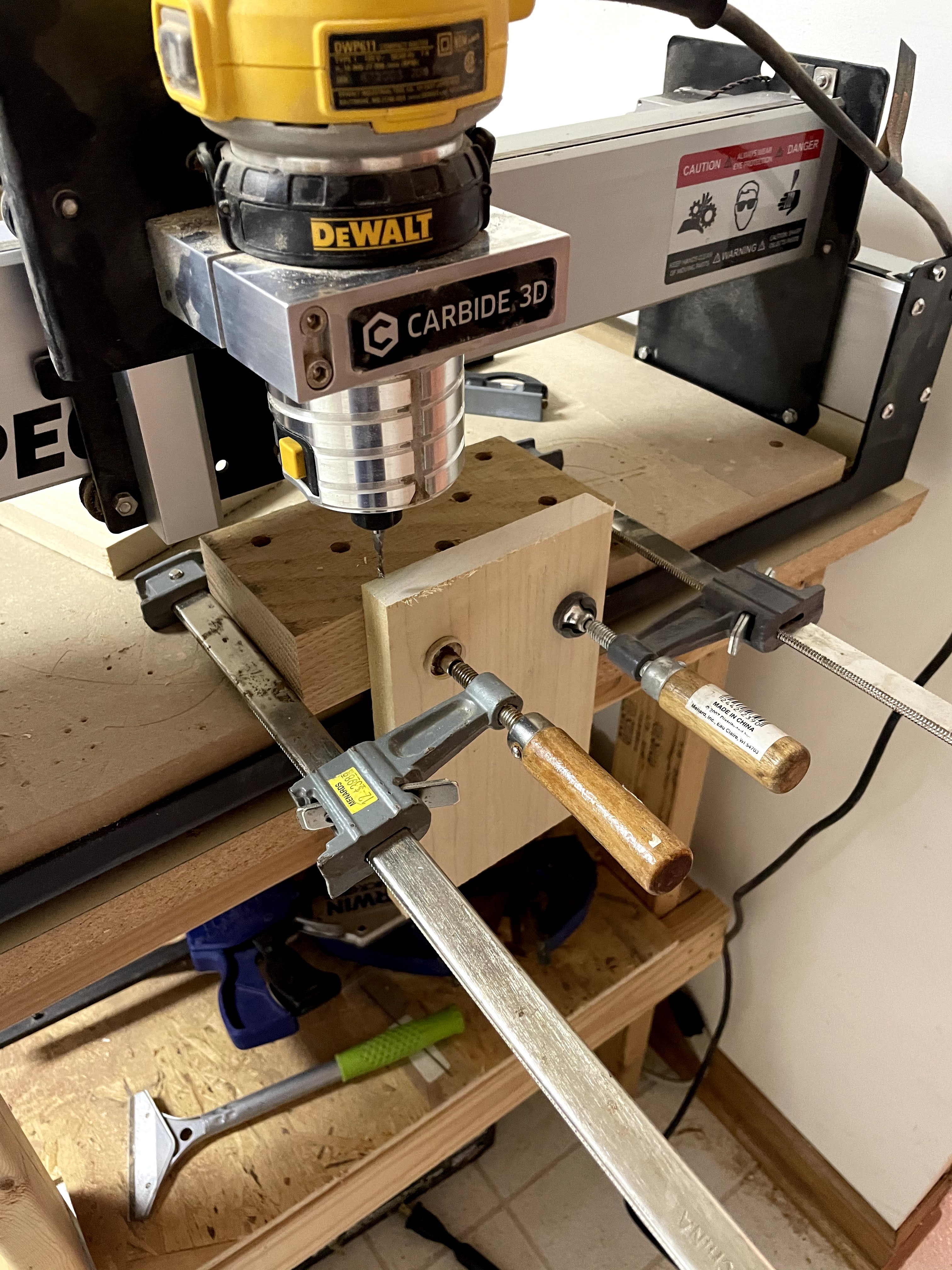
To hold the vertical board I followed ScottsdaleSteve method and attached a 2" thick block of scrap oak to the spoilboard that I had made square on my jointer. I then clamped the board to this block and routed out around the letters.

For the other board I just screwed the board to the waste board since this was a quick and dirty proof of concept and routed out the interior of the letters. I then lightly sanded both pieces and used a mallet to connect push them together. It was a very tight fit and actually broke part of the G off. I used a pocket offset of -.002" for the letters and will likely increase that for the final parts. Workholding is something I still struggle with and need to figure out how I am going to do it on the final boards to avoid the screw holes.

The other part of this project is I want to route out the lego portion in the middle instead of using a plastic plate. I’m currently stuck on how to make a nice enough end grain portion for this part of the build. Plan is to reinforce the fibers with cyanoacrylate glue before routing.

Part 2

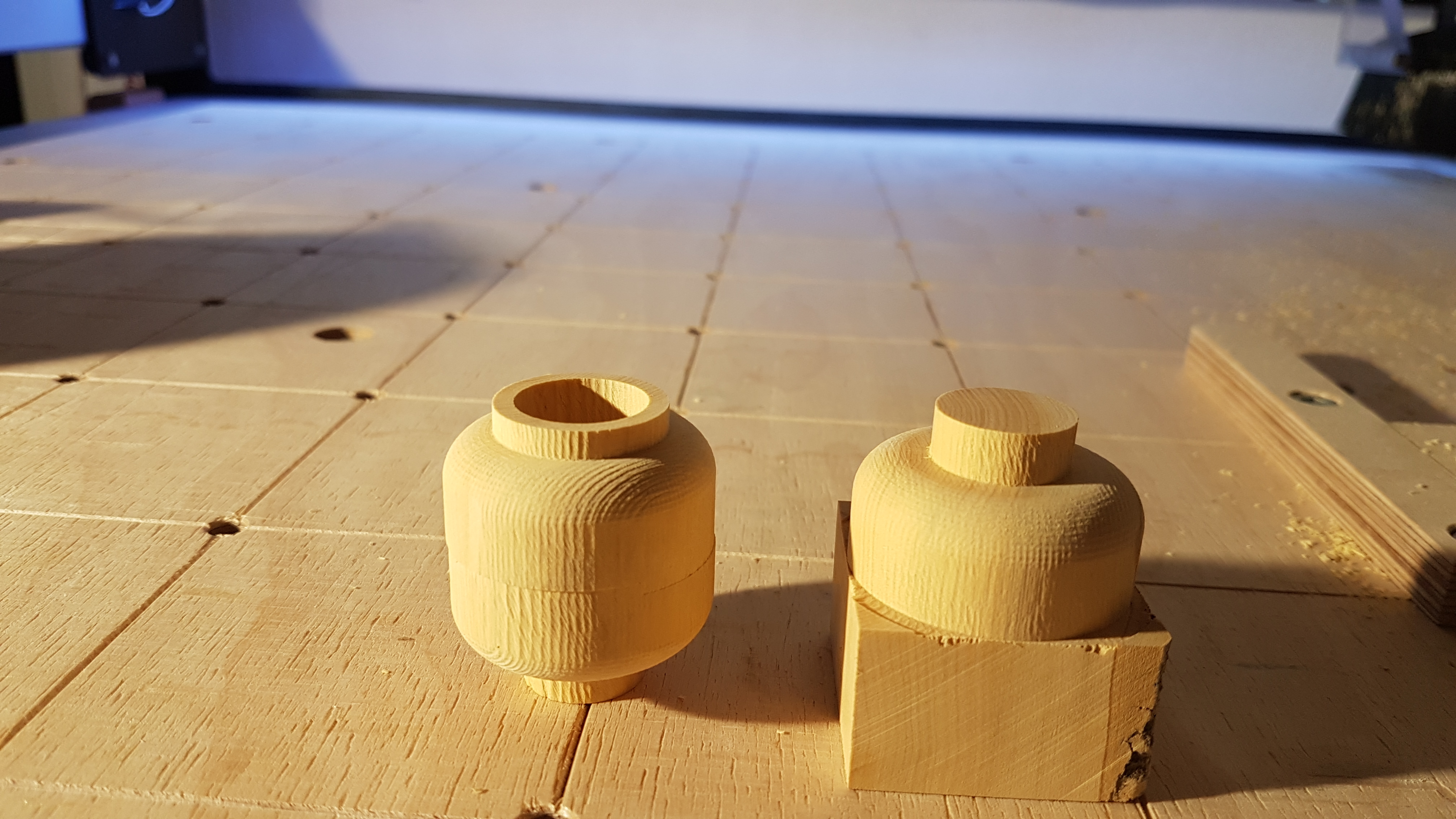
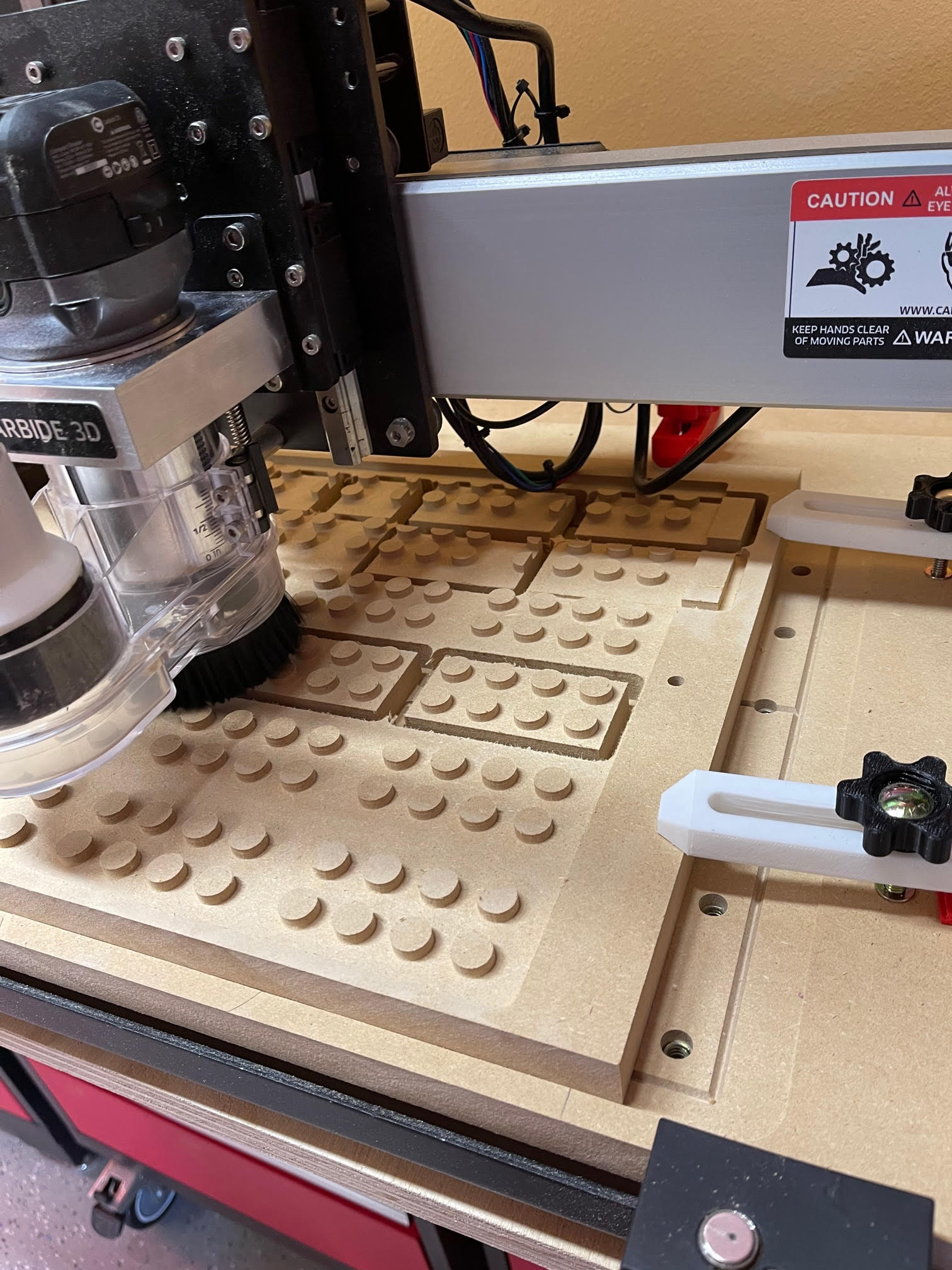
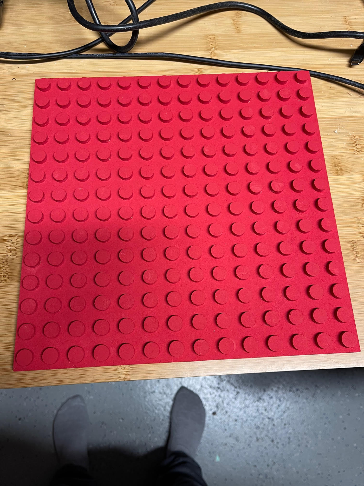
I bought some more clamps and was able glue the end board blank together. I used the CNC with a 0.250 end mill to flatten the top and bottom. I used a scrap cutoff from the main section to dial in the diameter that worked best with the wood and bit I was using. I used a Whiteside RD1600 down cut bit which worked great in the end grain. In the end I found a circle diameter of 0.195" worked best to give a part that could be disassembled, but not be too loose that they just fall off.

The file is just an array of circles with a diameter of 0.195 and gap of 0.315.
Lego board portion Final.dxf (6.6 KB) I was very happy how this turned out and the end grain works perfectly. I had thought about adding a chamfer on the top with a v-bit but decided against it. In the future I would do that step to help the lego pieces get started
easier.
I did end up reinforcing the end grain with super glue. I did not have accelerator and the glue never really cured in the interior. It stung my eyes a little while I was carving the pegs. On my test piece I tried with and without super glue and didn’t notice a differnce. The board did surface to a smoother finish after the glue was applied. (I surface the wood, applied super glue to entire surface, let sit for 24 hours and then surfaced again).

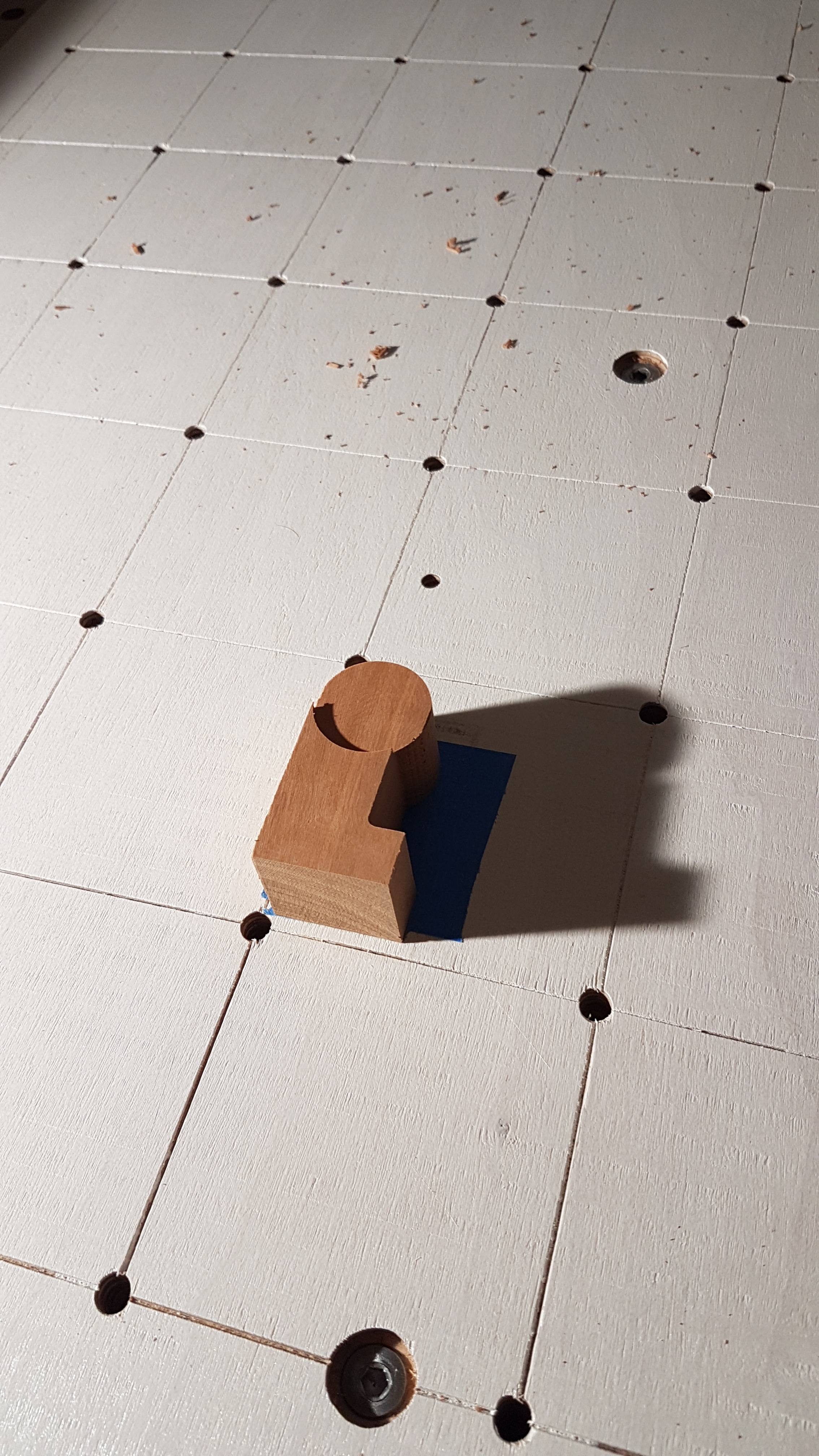
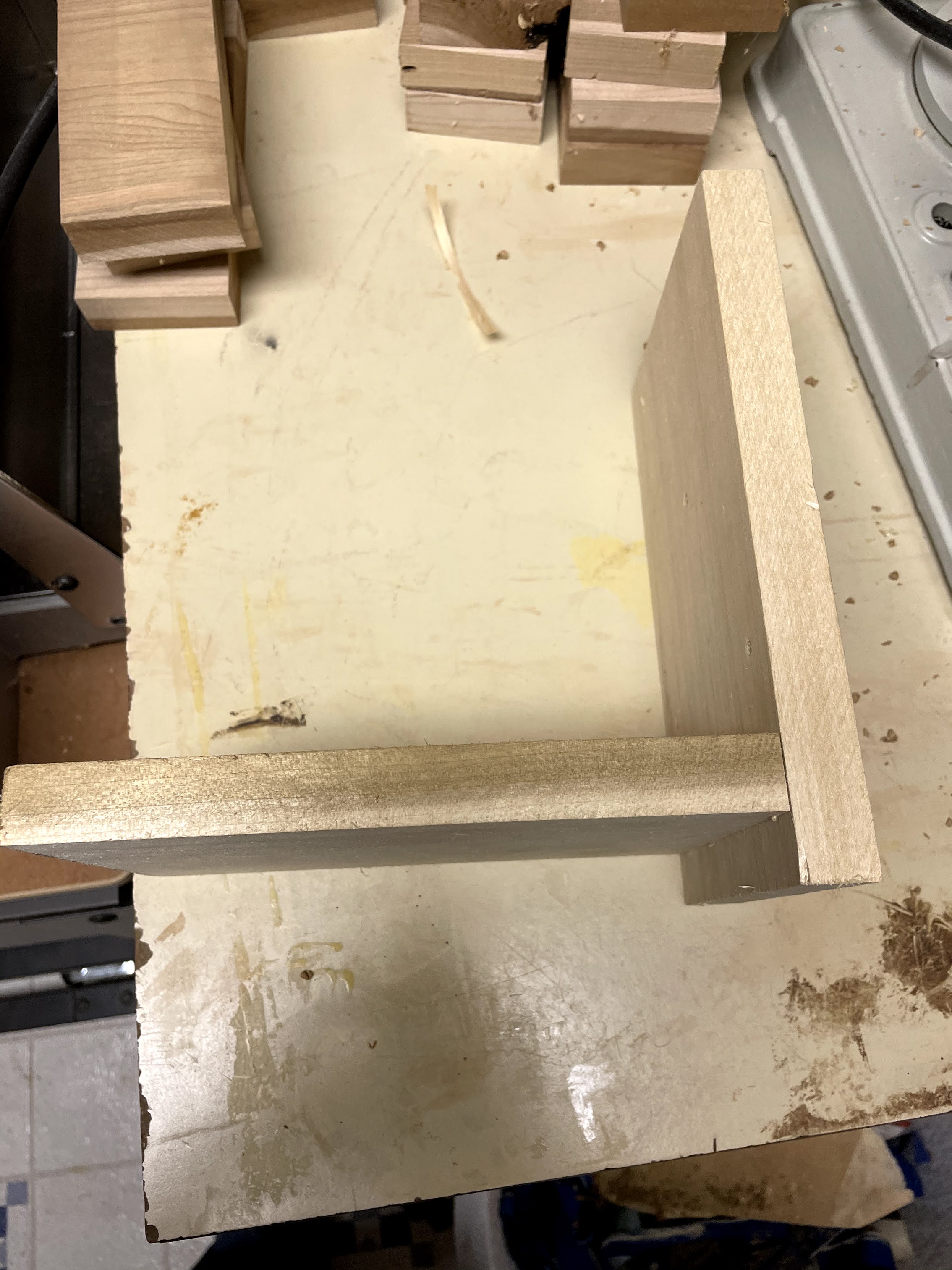
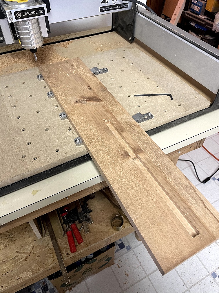
As a Christmas gift to myself I picked up some of the carbide 3d end stops and the tiger claw clamps. I then used the router to create the slot the main table board will sit in with the #201 0.250 end mill. The clamps saved me a lot time and I wished I would have bought them sooner.

I was going to use the same whiteside bit for the joint portion, but I realized it only has a cutting length of 1/2" and gets wider above that height, making a loose joint. An emergency order to amazon later I used the Amana Tool - 46125 bit to carve the joint. My one mistake was making the letters exactly the height of the board. Even with very careful positioning, I always ended up with some portion of the letters not being carved. If I would have made the letters .73" tall instead of .75" it would have worked fine. Before carving I adjusted the letter spacing such that the letters did not overlap the slot.

Lego connection 5.5 inch.dxf (61.1 KB)

I made the letters 1/16" deeper then the boards they were inserted into to make sure they were proud of the other board and could be sanded flat.

When cutting the pockets I used -.0035 pocket allowance to create a tight fit, but not too tight. On my sample I used -0.002 and it could be pounded together, but not hand assembled. This is a toolpath option on varve that doesn’t seem to exist on carbide create This can probably be done with an offset path on carbide create to create a new vector, but I haven’t tried.

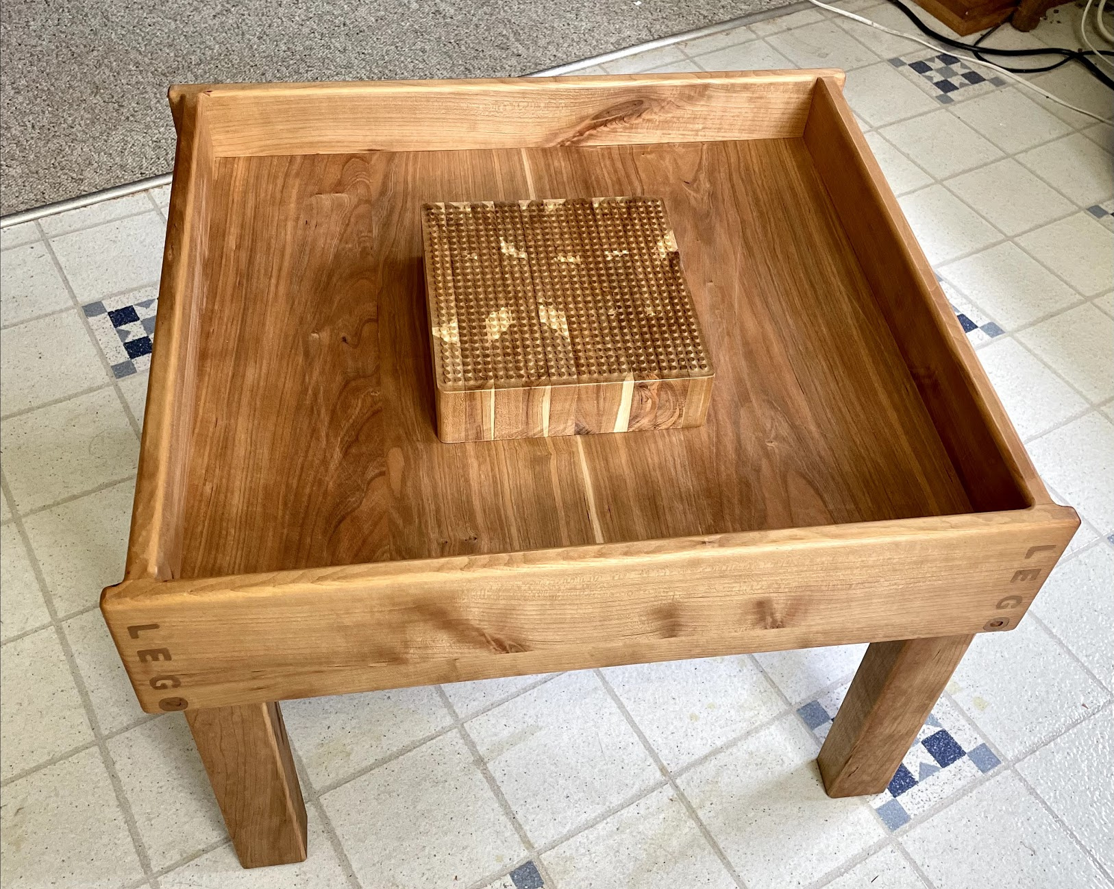
I then glued the joint together and put a 1/4 roundover on all edges since this is meant for young kids. I still need to build the legs yet, but I am out of time for the contest. Normally I would wait until project is complete to apply any finish, but with project deadline I applied the first coat of minwax hand rubbed polyurethane to get a picture of the final project (minus legs)


Cutrocket link

The vcarve files are below.

Lego connection 5.5inch Final design with fixes.zip (1.3 MB)

Just added legs and another coat of finish:

9 Likes

5 days to go, I’d like to see more Lego things!
@peterwup maybe ? (hint hint)

OK - I’ve been at it for several days with this challenge. I’m a complete newbie/green bean here but it’s been quite fun and learning so much. I’m not finished yet and will post final pics later but figured I would add to this amazing forum.

So my idea stems from always having a hard time finding my tools so I clearly needed to hang this up near my SO3. So instead of just using pegboard, I decided to make a lego wall to hang the parts.

I designed the lego’s all in Carbide Create from the industry standard Lego Sizes… I needed a few base plates to hang on the wall and then several pieces to hold the things I would use to hang the tools.

I’ll start with my key learnings so far - which have been way too numerous but I think that’s part of the challenge and learning.

  1. Cable drag - I just have the standard SO3 and thought I followed the instructions to a T, but as you can see from this picture, the cables drag too much in the back and it threw off the machine while cutting so I ended up not having as many pieces as I’d designed. But I added one more cable tie in the back of the machine and it does not drag any more and should not get caught anymore

  2. Workholding - here is where I seem to think I’m getting better but everytime something new happens. I have 3d printed many different size clamps but I either had them too close to the cutter or in the way of the Sweepy. I also was trying to fit the biggest size I could on the SO3 vs. just wasting some wood on the side. I also now have double sided tape that I should use if I’m cutting to the max.

  3. Precision - I first designed my piece to be 14.3" square and just cut it on my table saw, thinking I would be “close enough” to 14.3" so when I turned it over and cut the front, it would be close enough… But even just being a tiny bit off threw off the back. So the next time I had had the machine cut two 1/4" holes that went into my baseboard that was symmetrical so that I could turn it over and just push in two 1/4" bits to get it aligned exact the second time when cutting the other side.

  4. Carbide Create - I learned so many things trying to get it both designed and create the toolpaths.

a) I’m still struggling for a good way to pick lots of things at once without having to click each one while holding down the shift. I found that if I grouped some of the common circles for the cuts, then selecting them would be faster to make the tool paths
b) I was hoping to use the 1/4’ bit the most but the first time I designed it, the space between the outer wall and holes was less than 1/4". But then I read more on this forum, and just created an artificial outer box where the cutter could cut, and then made it around 50% faster. So learning how to offset to make cuts was an important learning for me
c) Carbide Create seemed limited to me at first, but when I really started learning it, there is really a lot of good stuff built in (centering to last object or stock, offsets, boolean, etc…)

  1. Random disconnects. I’m still having them but Carbide 3d team has been awesome in helping me try to isolate it. I was making all my cuts with one .nc file but learned that even with a disconnect, it would not lose the zero point, so I could just do another .nc file without the cuts that were completed. I’m confident I’ll get the random disconnects fixed soon.

Here is my completed base plate:

And here is the first part of hanging tools. I just used a small nail into one of my lego pieces.

My tomorrow project is to stack a few of my bricks together and then cut squares in the top so it can hold my CNC bits and then drill some holes to hold the allen wrenches. I hope to expand this out with another base plate and hold my headphones and eye glasses. It’s all painted red/black to match my wall cabinets.

More pictures tomorrow. And any ideas/recommendations/tips would be hugely appreciated. I’ll upload all the lego parts later too - they actually work and stay together (if I take all my learnings into account).

20 Likes

That’s what I am talking about! Thanks for the early sneak peek.
The red and black colors work very well I think, that should make for a pretty cool workshop space when this is all done, make sure to post a picture of that!

Can you post a pic from the back of the machine? There is definitely too much length there, you should not have those loops visible at the bottom (or did you maybe fix that in the meantime?)

That’s where side clamps like the Gator Tooth and Tiger Claw are handy, they allow you to have the top surface completely free for the cutter/Sweepy to go as far out as required.

Give painter’stape and superglue a try, I find it to be superior to double-sided tape, cheaper, and it is well suited for regular S03 work area (it becomes awkward to use for very large pieces, so XXL users may not use it as much as I do, which is all the time)

That’s a best practice for precise double-sided jobs so it will come in handy quite often.

Just in case you missed it , there are two drag box selection modes: when dragging from the top left to the bottom right, it will select all objects that are completely within the box. When dragging from the bottom left to the top right, it will select all objects that are at least partially within the box. This second mode can turn out to be quite useful, say if you want to select a series of objects that are aligned, but with other objects in between them; if you can find a location where you can draw a vertical or horizontal line touching only the objects you want selected, you can use that mode.
The other obvious tip is to select lots of things and then remove things by holding the shift key and clicking on them. And then again there are designs where you will just have to painfully hand pick the selection, and then grouping is great to only do it once.

Looking forward to seeting the completed project!

2 Likes

Thanks Julien - very, very helpful guidance. I’ll send a pic of the back of machine later as I do think something still might be wrong

I’ll look into other workholding devices as you recommend and will try painters tape and Superglue too.

I did miss the way to select multiple items depending on which direction you go. Where do you find all these type instructions? I had a hard time figuring out how to pan around after zoom and the forum helped me there, but would be good to know where to go for all the specifics of the software.

So here are more pictures.

Here is the way I cut squares to hold the CNC bits

And then mounted on the wall plates with my holder for the allen wrenches

Here is the near finished pics - notice my workbench if red and black so made the lego’s match…

I plan to add the Carbide C logo somewhere soon.

Again, I welcome any feedback and advice.

15 Likes

Here are the carbide create files. Now let the real help and advice come. Thanks

Lego Wall Carbide Create Files.zip (168.5 KB)

And here is the link to the CutRocket website:

5 Likes

The only resource I know of is this series of tutorial videos:

https://docs.carbide3d.com/assembly/carbidecreate/video-tutorials/

They were made a long time ago so CC evolved since then, but most of it should still apply.
I am not aware of a full-fledged user manual, but maybe @WillAdams knows. He is also the best reference for all things Carbide Create :slight_smile:

That is a great workbench you got there.