@DWood and @Jairo, thank you for your entries! very creative.
@DWood: no need to upload the design file indeed as you posted all the required info to recreate this.
@Jairo: if you don’t mind can you attach the actual c2d file in your post ?
2 Likes
brick13x14_63.c2d (1.1 MB)

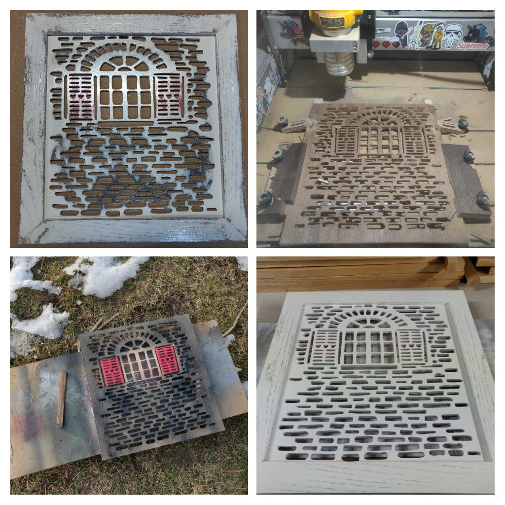
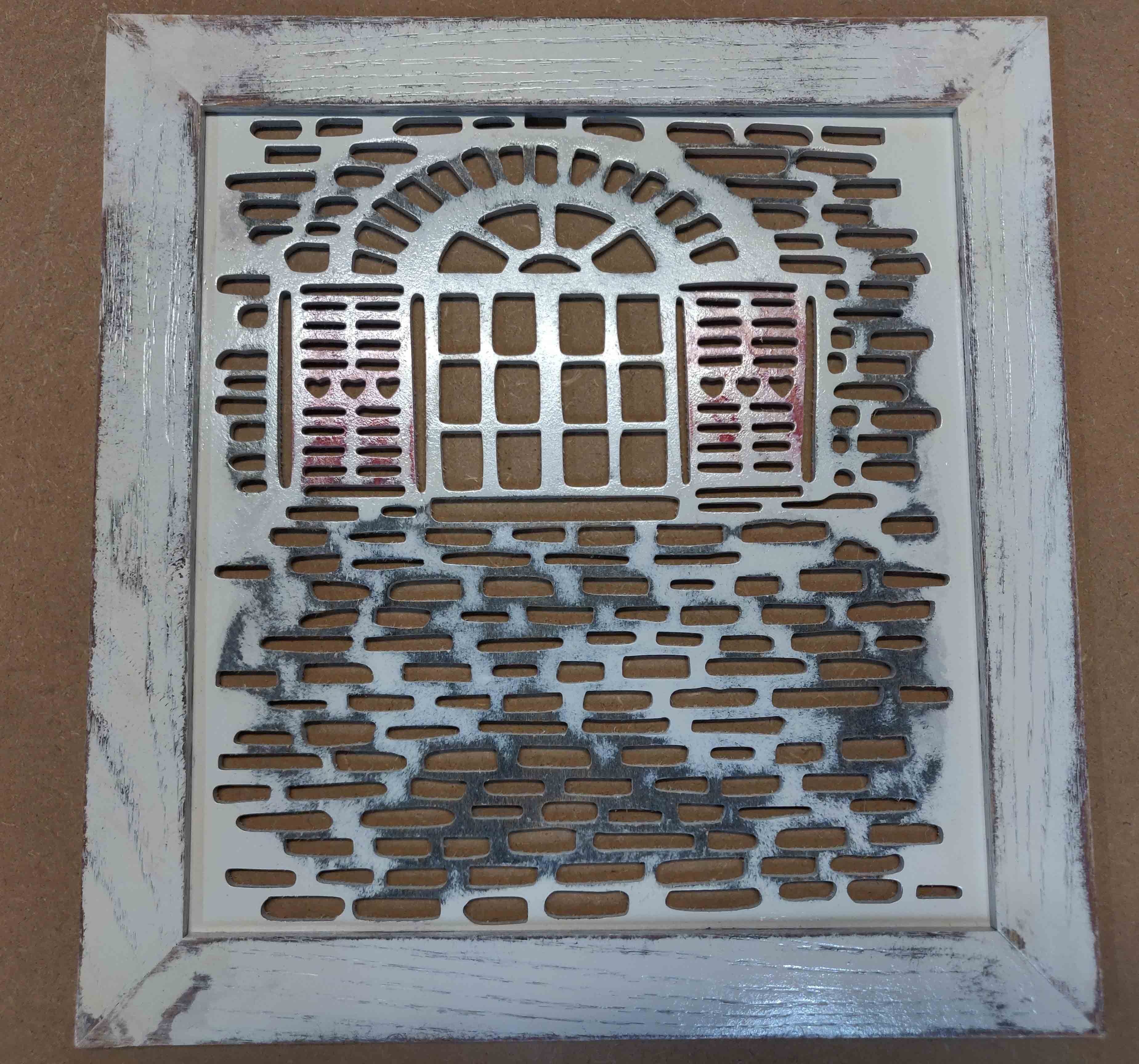
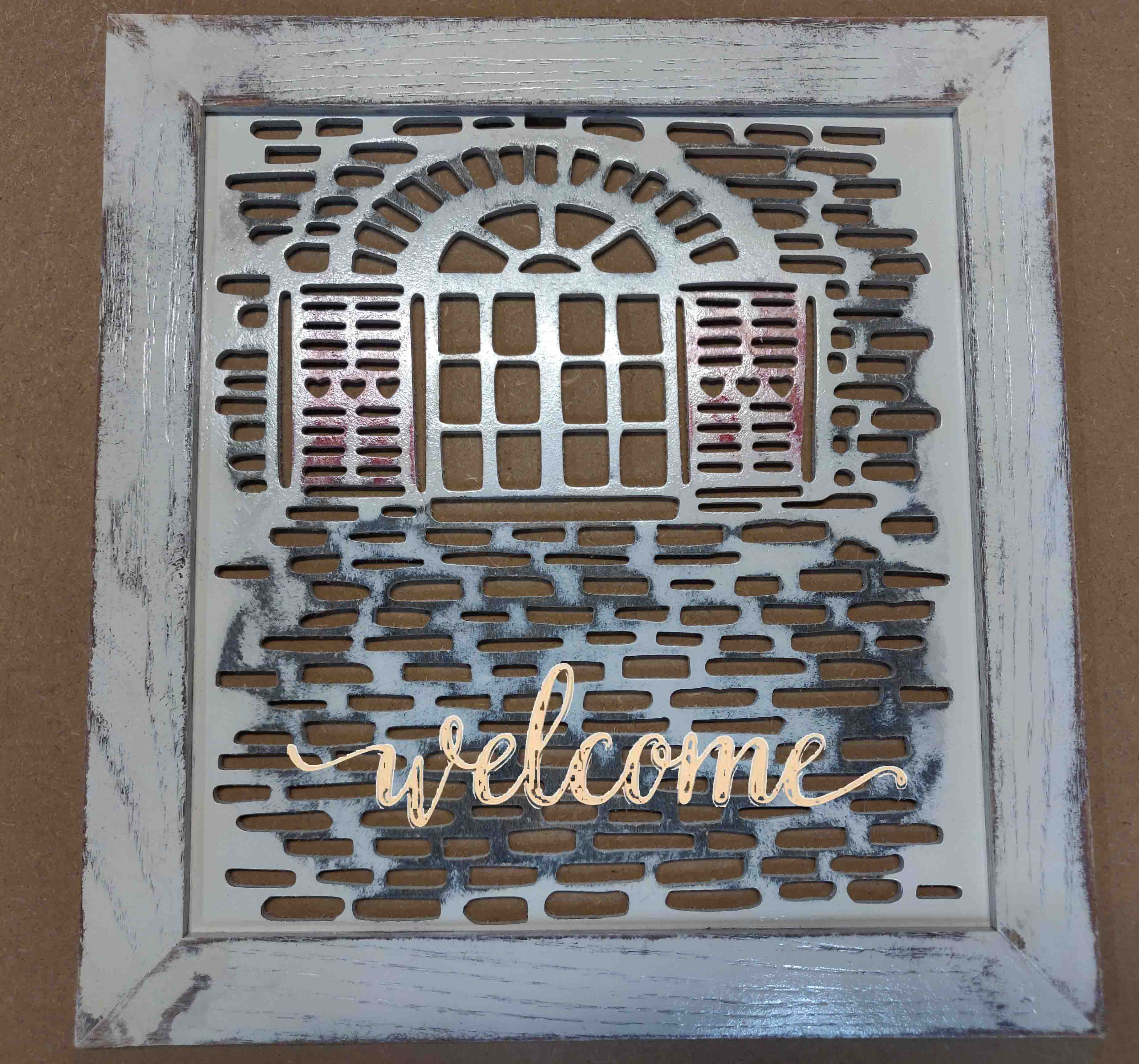
So I started working on this and wasn’t sure if i’d get it complete on time. I still intend on adding a welcome message in similar color. This is to hang by the front door of our house.
I used the same process as before
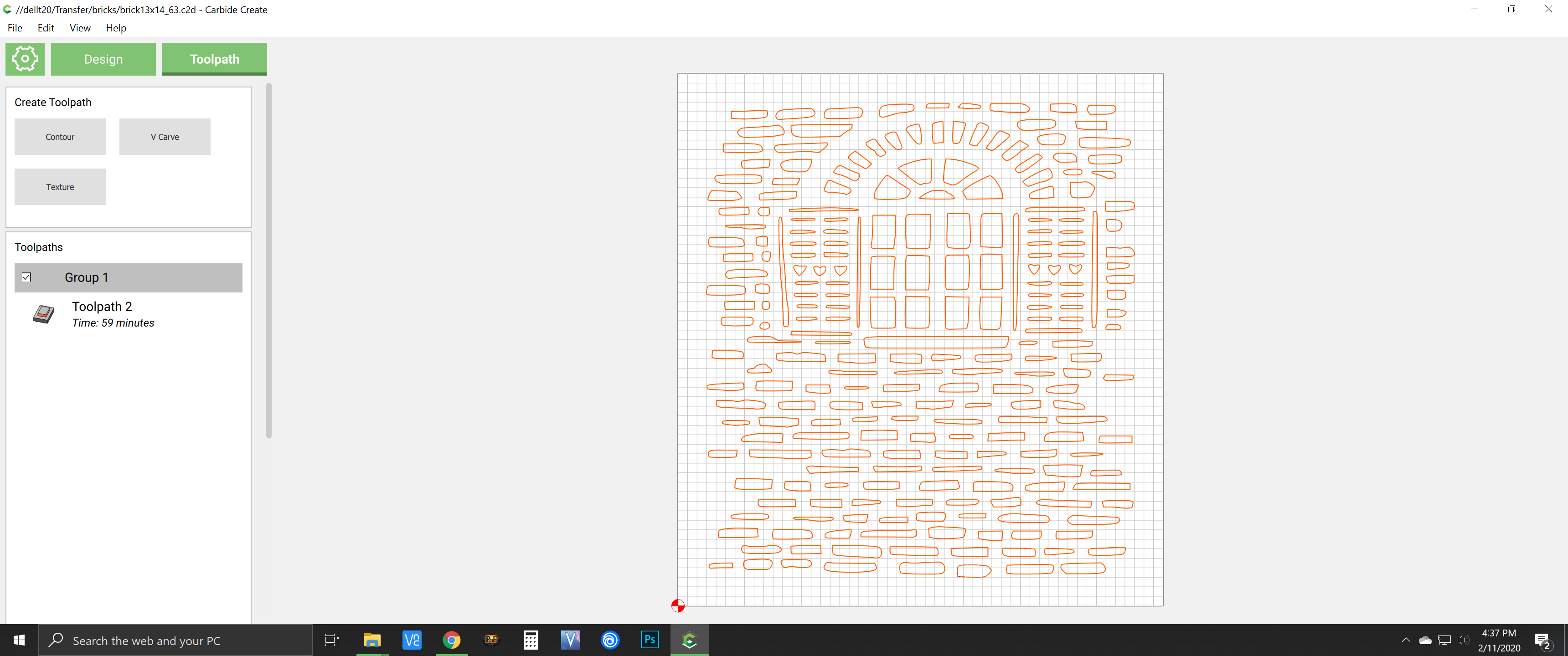
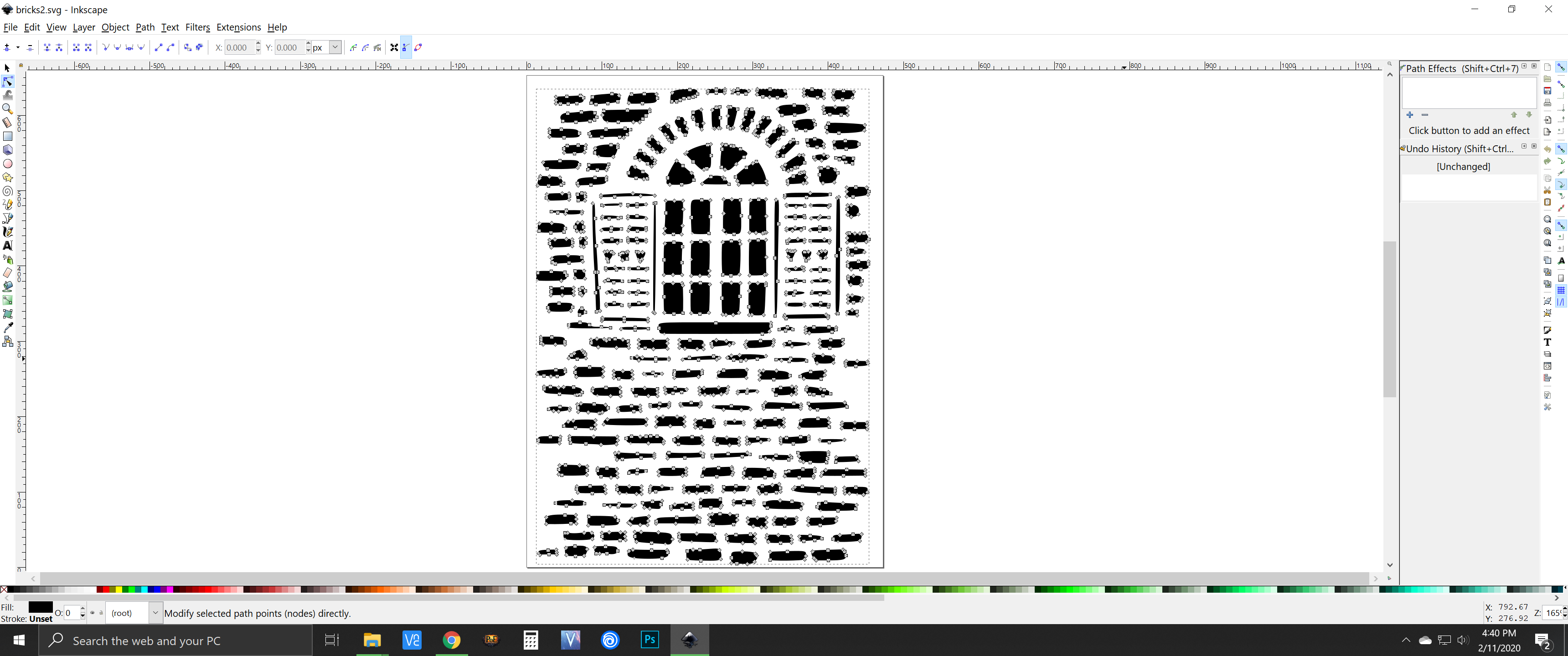
Workflow:
Import JPEG image to inkscape --} Trace bitmap to create vectors for paths --} Save SVG --}Import SVG into CarbideCreate and Create your Gcode
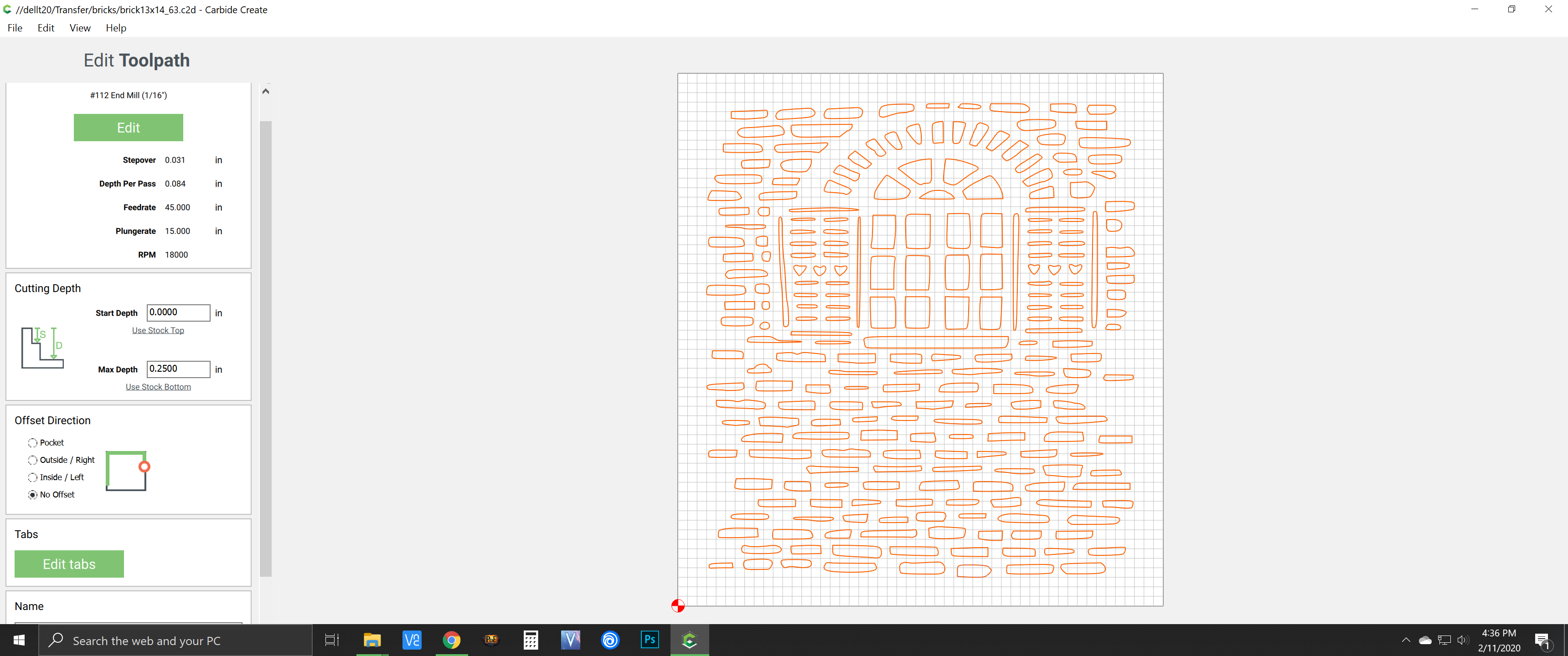
I used 1/4 plywood mdf core with a 1/16 end mill. The frame was made with some oak. Spray painted, then sanded thru to give rustic effect (first try at this), then sprayed it with some clear.
I still plan on adding text, just ran out of time before the deadline
6 Likes
Don’t mind at all, I didn’t have the file on my iPad, when I created the post yesterday.
I edited the original post to include the c2d file.
@Julien thanks for doing these challenges. We just got our S3XXL at the end of September last year to get us through a bottle neck we had in our shop during the holidays. We absolutely love this machine! We are planning on participating more in the challenges, time permitting!
2 Likes
This was good fun!
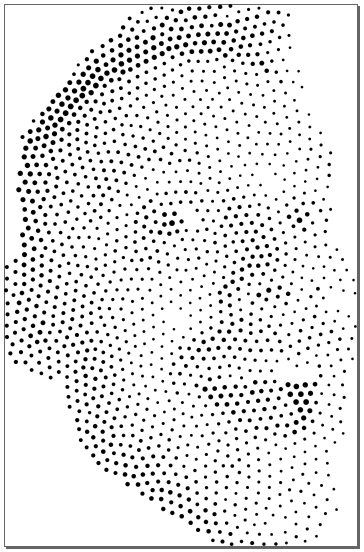
So for this CNC decorative see through panel challenge #4, I thought I’d do a Sea-through panel using the Shapeoko SeaNC. That’s it for the puns, I promise. My idea was to use a halftone image to create a panel that would reveal a sea surface image when viewed from far enough away. This ended up being an adventure into the limits of the Carbide software suite that was definitely unexpected, but I think lays out a pretty convenient workflow for making all sorts of custom art from anywhere on the Shapeoko.
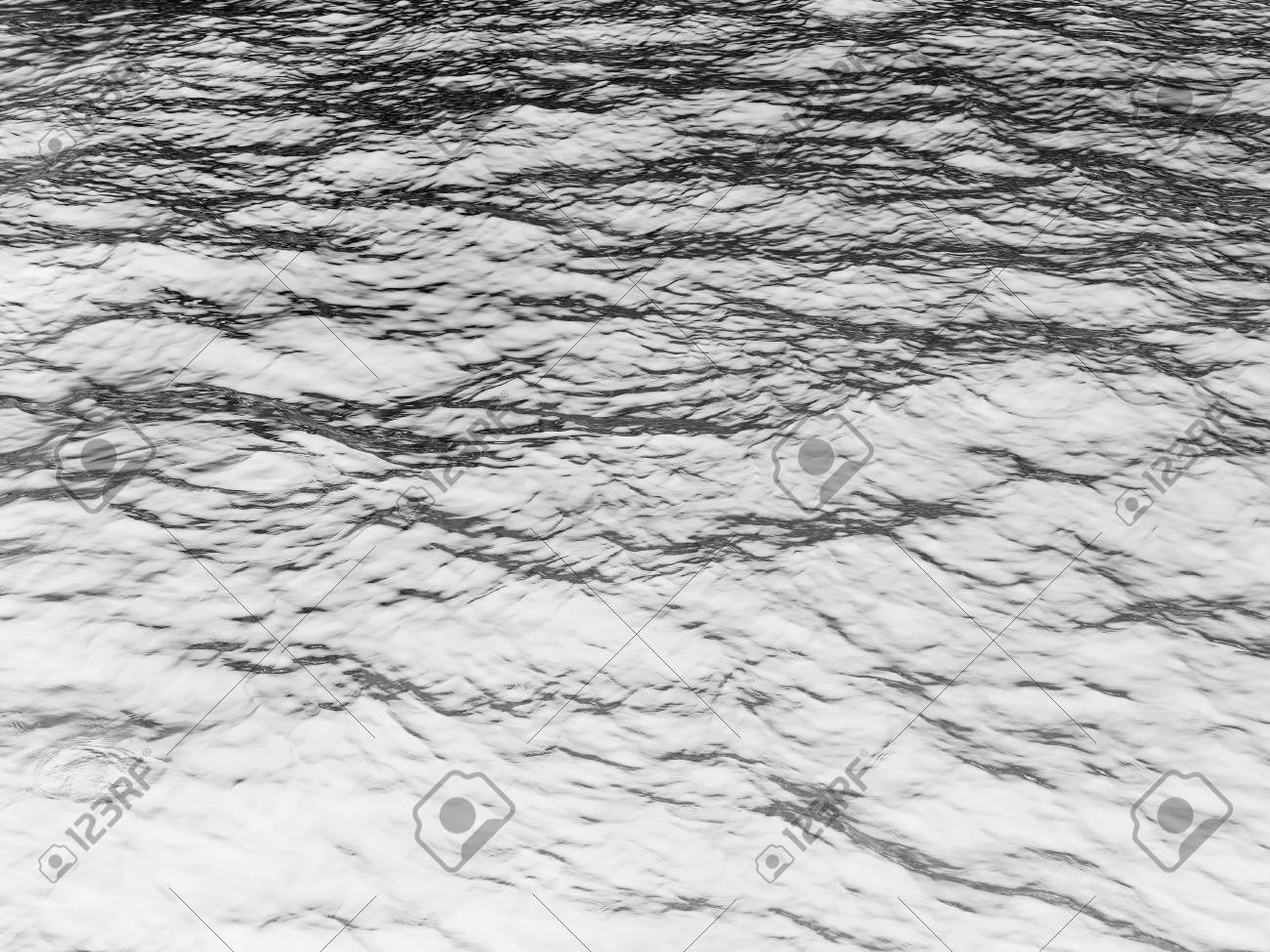
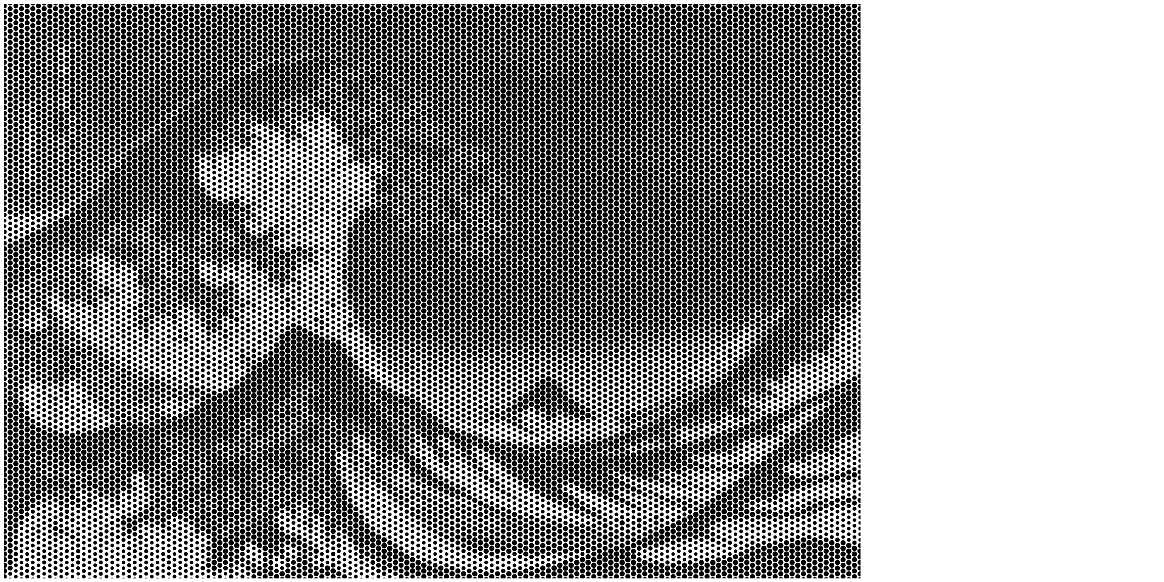
To stick with the sea theme I found so clever, I started with an stock image of some open water and used the online tool Rasterbator to create a halftone file of the image. In my case, I had to invert the starting image to have the halftone dots be heavier in the right part of the image.
Using the Rasterbator website is fairly straight-forward to use and free!
- Upload your image or point to a url.
- Choose a custom final size to match your work piece or layout
- Chose a black hole and white background color scheme.
- Set the grid size and raster size percentages.
::Record scratch:: I should add now, because I found out myself much later, that one should plan their minimum hole size now so that it fits their tooling. The help page on the site explains how the grid size and circle sizes are calculated. Save yourself at least one headache and plan ahead. - Download the file.
The Rasterbator file is a pdf, so I opened in Inkscape and converted to SVG.
Starting Image:

Inverted Image:
Rasterbated Image converted to SVG:

The first unexpected challenge was using Carbide Create to program the toolpath for so many elements at once. I think it was at this point I should have realized I was maybe going beyond what was reasonable to expect from the software. The large number of elements (almost 5000 circles!) really took a toll on Carbide Create and manipulating the file took a few tries between the crashes and optimizing the circle size to fit the #112 cutter I planned on using. Each time I tried to generate the toolpath it took the better part of a halfhour for Carbide Create to finish crunching the numbers. C2D file below if you want to try it out, or point out how I could have avoided the mess. C2D file.zip (809.7 KB)
The next challenge was loading the file into Carbide Motion. The full file was a mere 28MB and didn’t seem to load. So I had to go back to Carbide Create to split the toolpath into two seperate files. Carbide Motion seems to be able to handle the ~14MB files. These smaller files were able to load into Carbide Motion.NC Files.zip (3.0 MB)
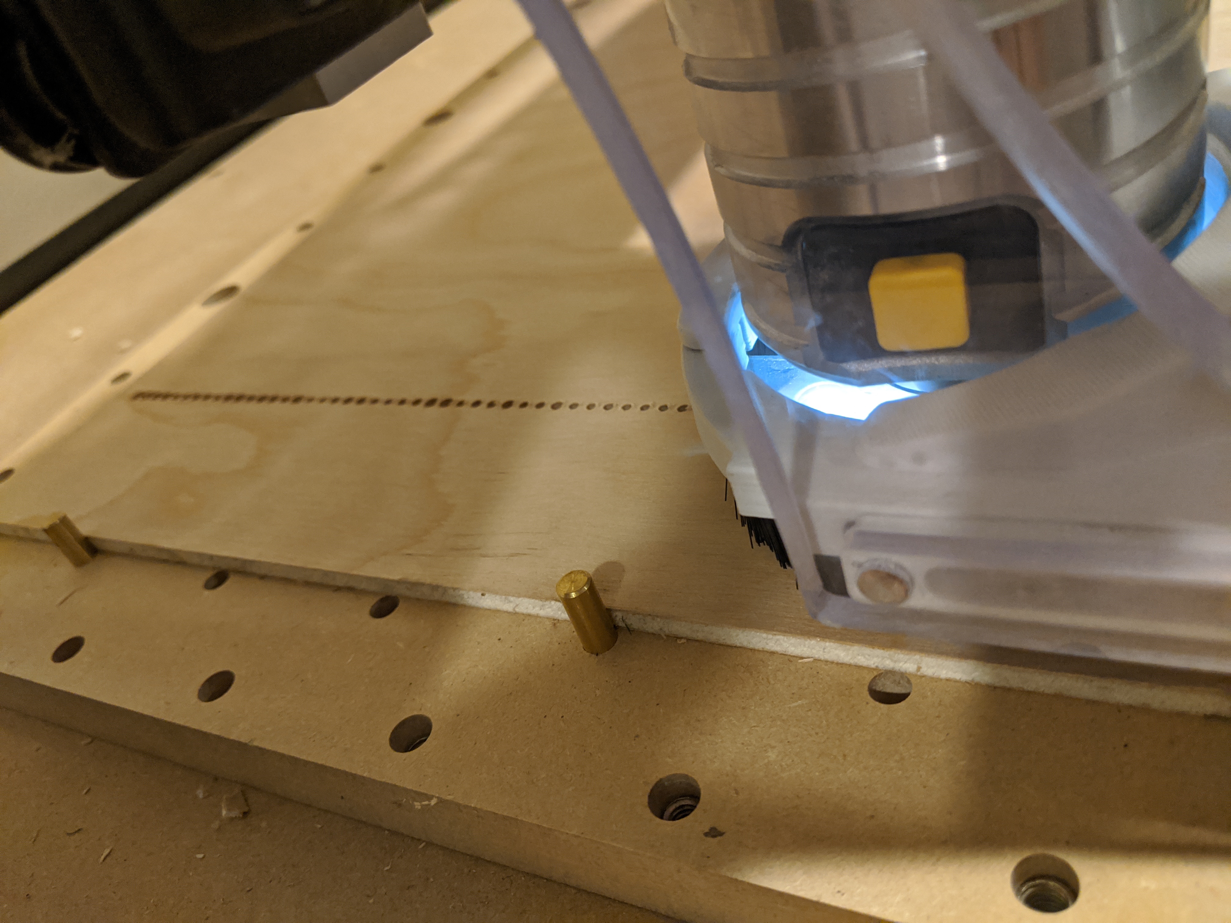
After that it was a pretty standard affair of choosing material, tooling, workholding, and then a lot of time. Total machining time was just about 8.5 hours.
Just Starting!
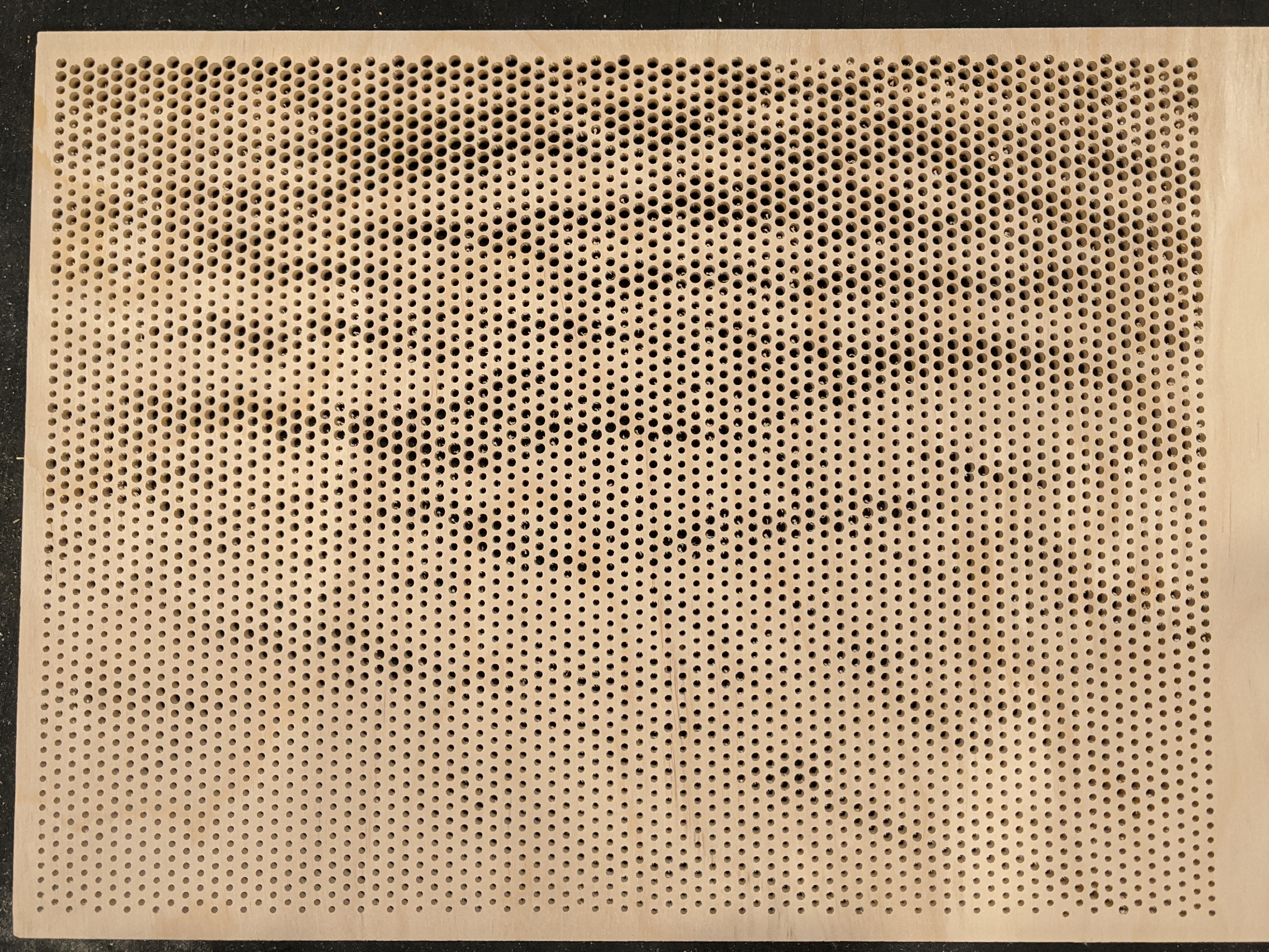
Halfway done!
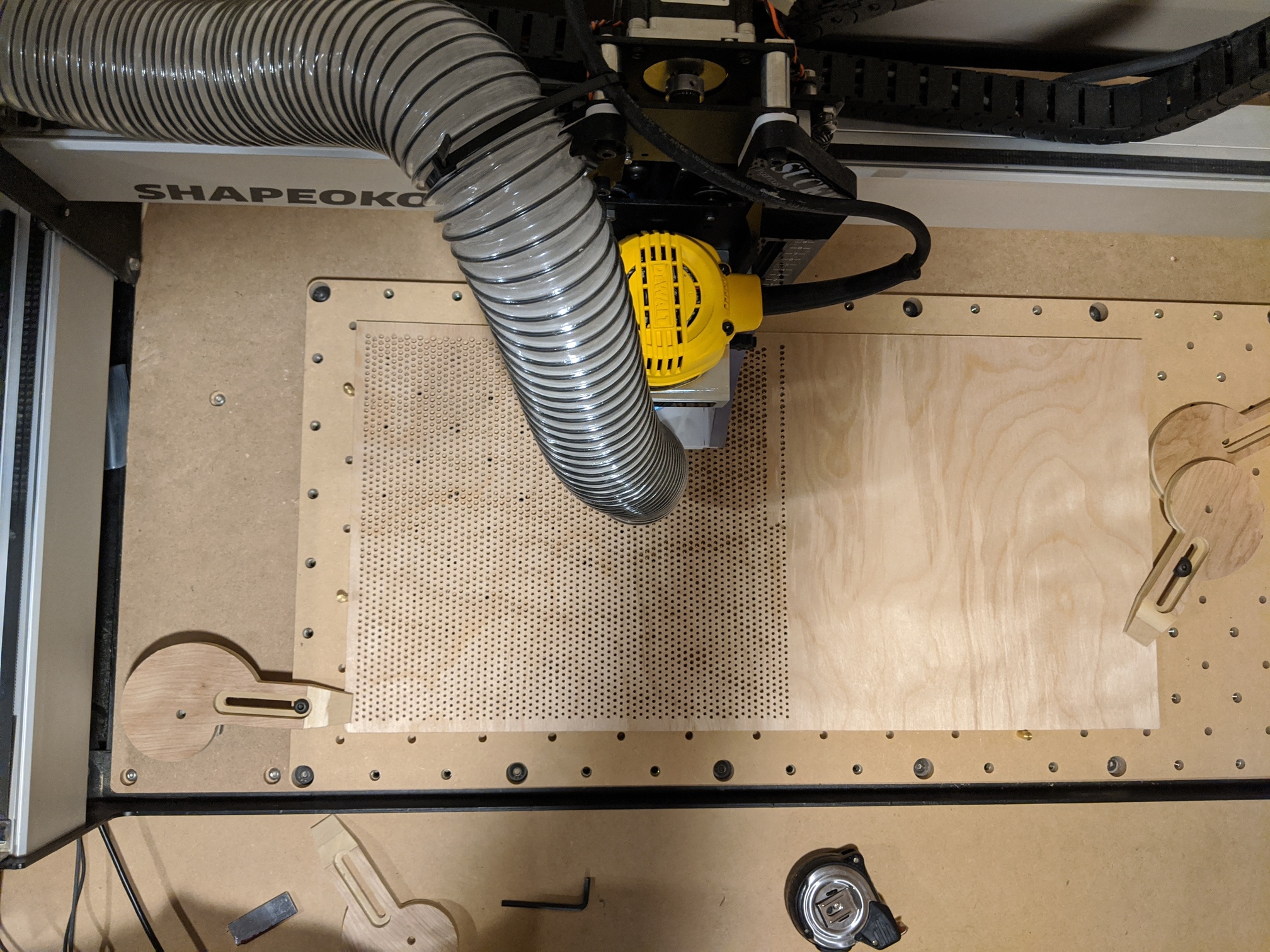
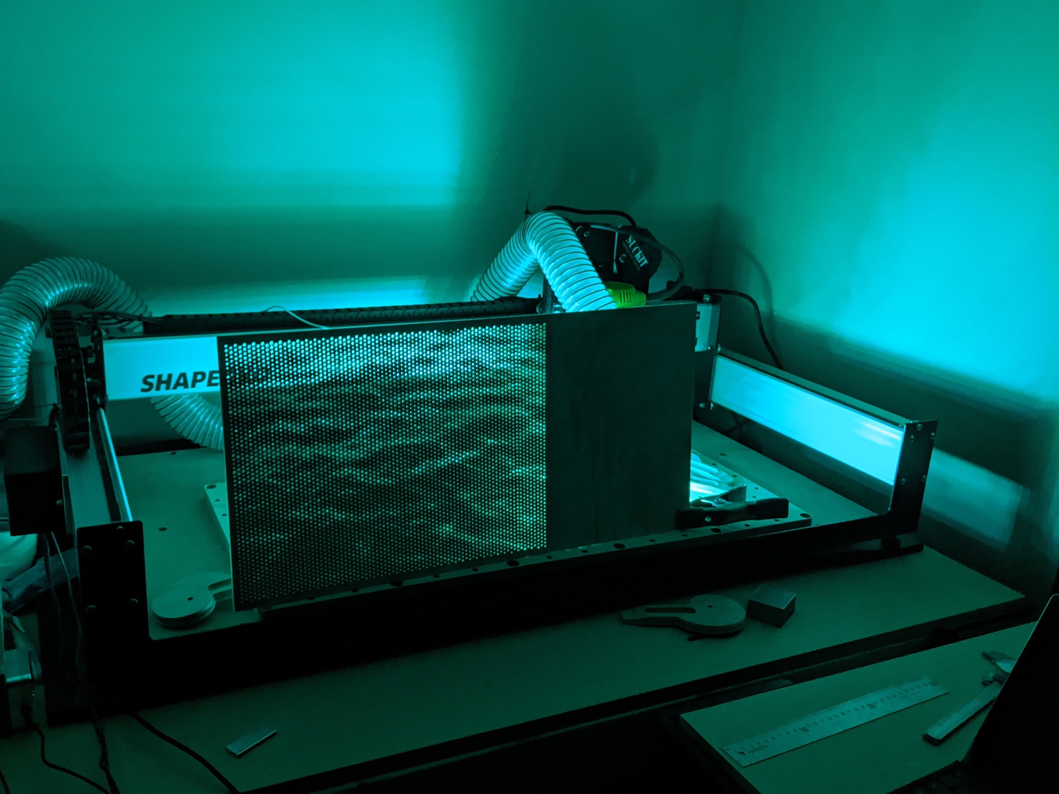
Material was a 1’x2’ 1/4" birch plywood drop I had from another project. The material was restrained using a couple of pins and some homemade cam/toe clamps made on the shapeoko. I used a Carbide #112 1/16 end mill. Afterwards, I knocked any fuzz down with some 220 grit on the sander and took some photos with LED’s behind the panel to show off the pattern. I plan to try @wmoy 's infinity mirror frame to make frame for the piece eventually. His everything looks like a nail when you have a CNC hammer approach to problems is, as always, inspiring.
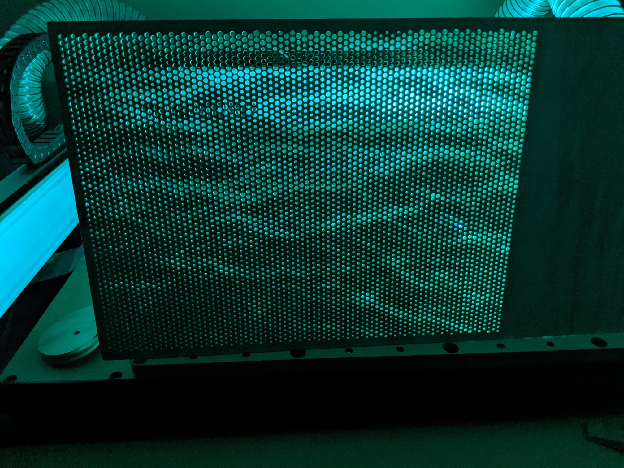
The end effect was more subtle than I had hoped, but that was a limitation of the range in size of the holes I was able to manage with my given tool and workpiece size. Best results seem to be when there is a large amount of contrast between the front and back of the panel. Nevertheless, thanks for sticking around and here are the final pictures.
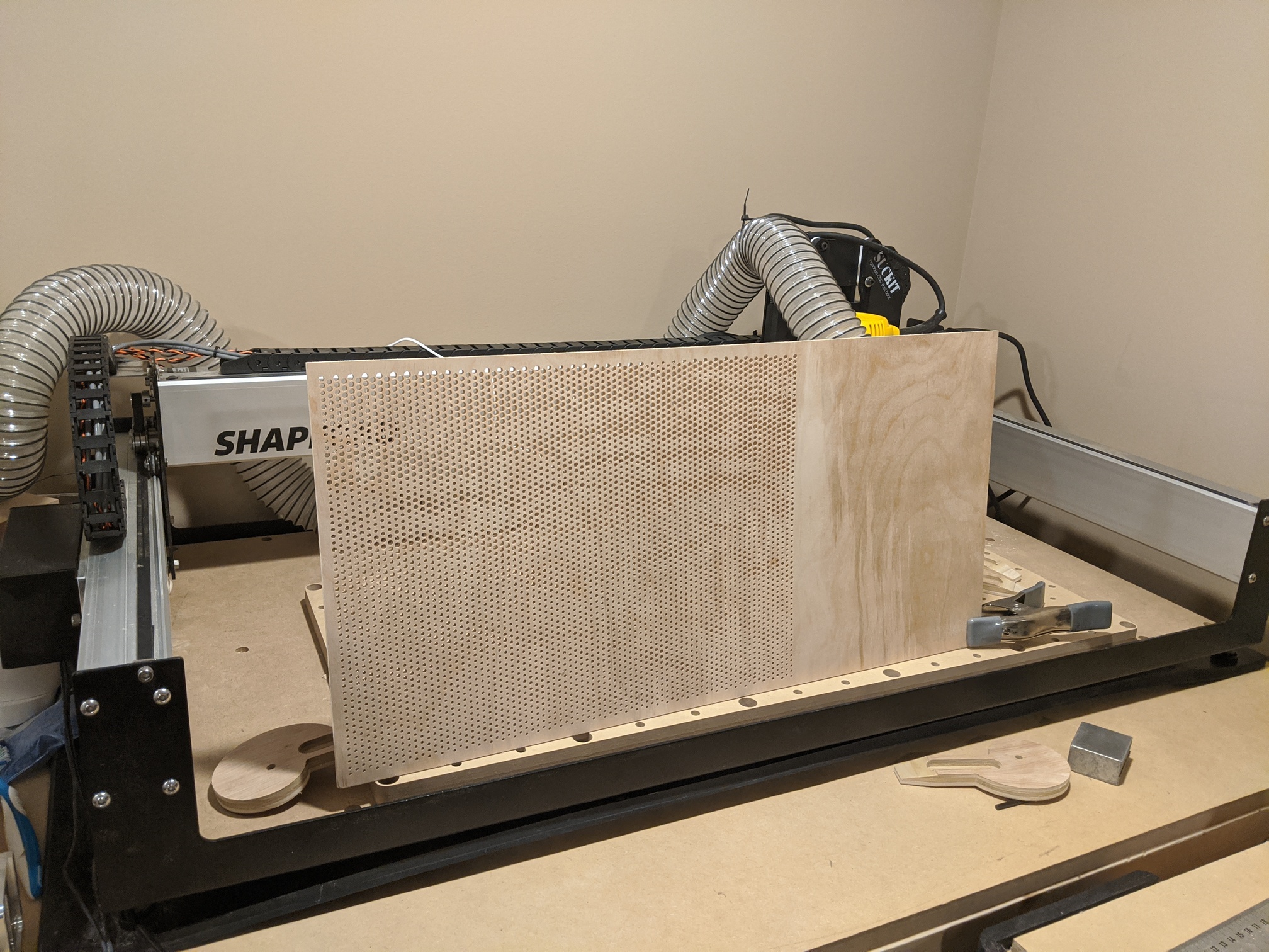
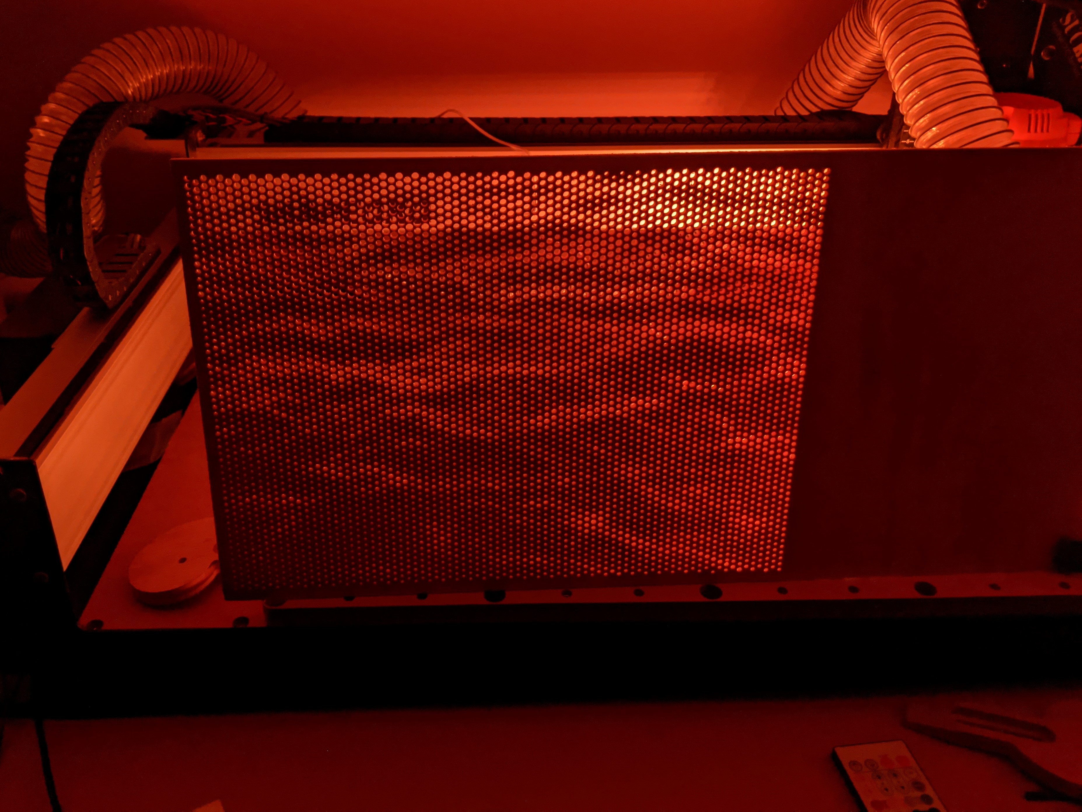
Finished Panel
Under Normal Light
Doesn’t show up too well

With a dark background the pattern starts to show up
Standing up, still not much showing up, but you can see through it!
In the Dark with LED’s
There we go!!!
Sunset
Best shot yet!
After seeing @MarkDGaal 's fantastic entry, I felt a wave of inspiration or insanity that the “Great Wave” may be the perfect followup to the more tranquil water scene I had made. Definitely a more distinctive pattern to pull out of the panel when being viewed. I thought I would try to get a second panel in to make my entry that much more impressive. However, I had to increase the grid size of the half tone imageto get the effect I wanted and the hole count more than doubled. I estimated it was about 13,000 holes.
Still, I went through the steps and set Carbide Create to work on the file and went to bed. The next morning the file had finished running in Carbide Create and the finished tool path and estimated run time was staring me in the face, 21 hours. As soon as I clicked the window Carbide Create crashed to desktop. I took it as a sign that I had gone far enough and would not be winning any prizes for not sleeping the last few days before the deadline, so it was better to stop while I was ahead.
Extra thought: I was slightly disappointed that the workflow to create these images may be limited by the ability of Carbide Create to handle large numbers of elements from an SVG. Is there a way this limit that can be designed around? Has anyone else found (un)expected limits in Carbide Create? How do you work around them. Thanks all!
11 Likes
So, I struggled with this challenge. Time and content. I really wanted to make something my wife wanted to hang in the house, but she is pretty particular. I toyed around with some organic looking things, but my that’s where I have a big hole in my design experience.
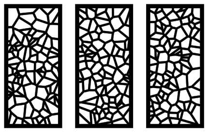
My backup idea was to do some random seeded voronoi patterns designed in inkscape, but they’d look very similar to @JaiFlors design.
Here was one iteration…I liked how it looked in a series. Wife said we had no room for that.
I even messed around with another Carbide 3D one:

I, like @duexx, thought to do the halftone (though I went for my face):
Sorry, it’s late…here’s my entry!
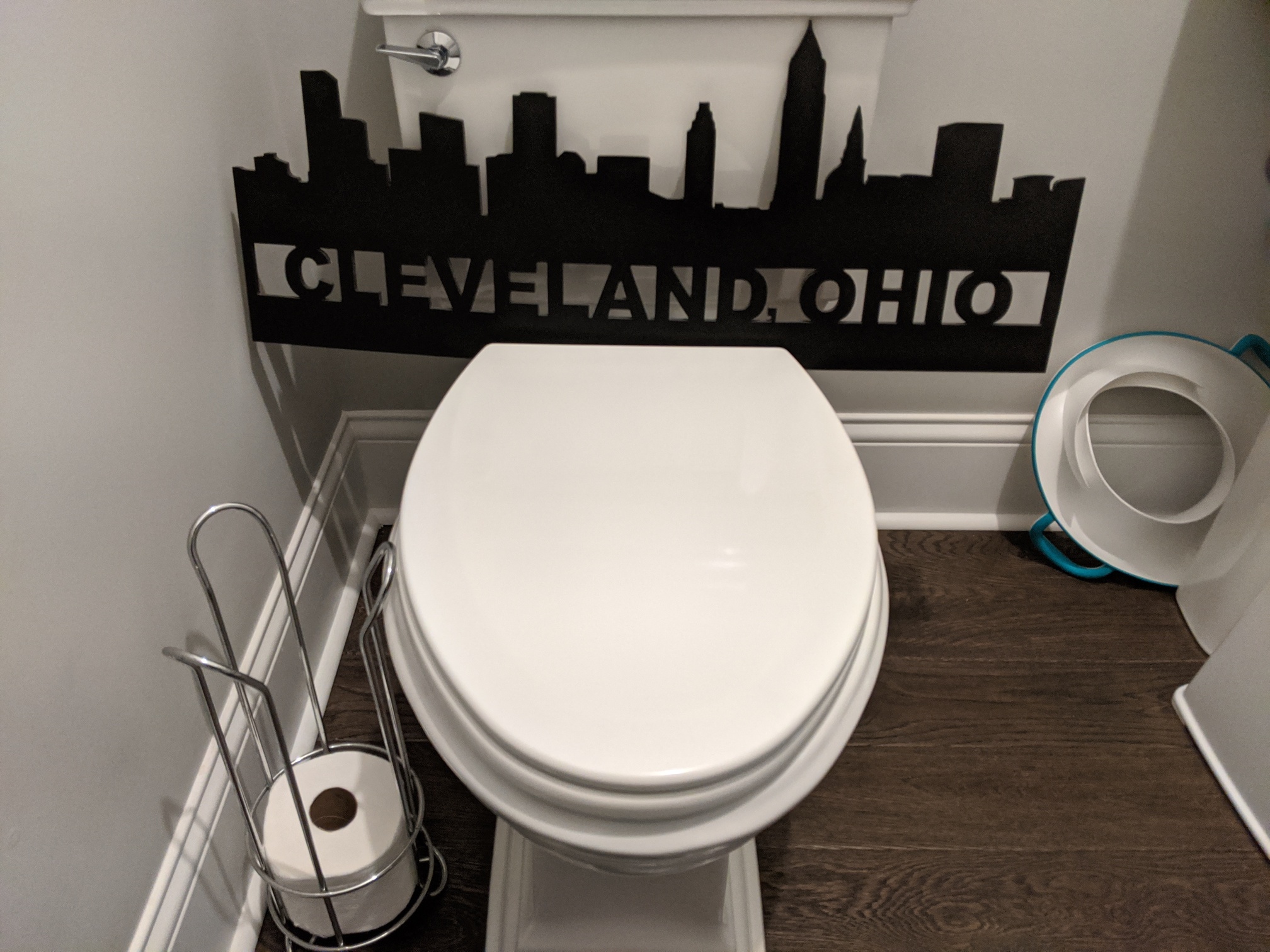
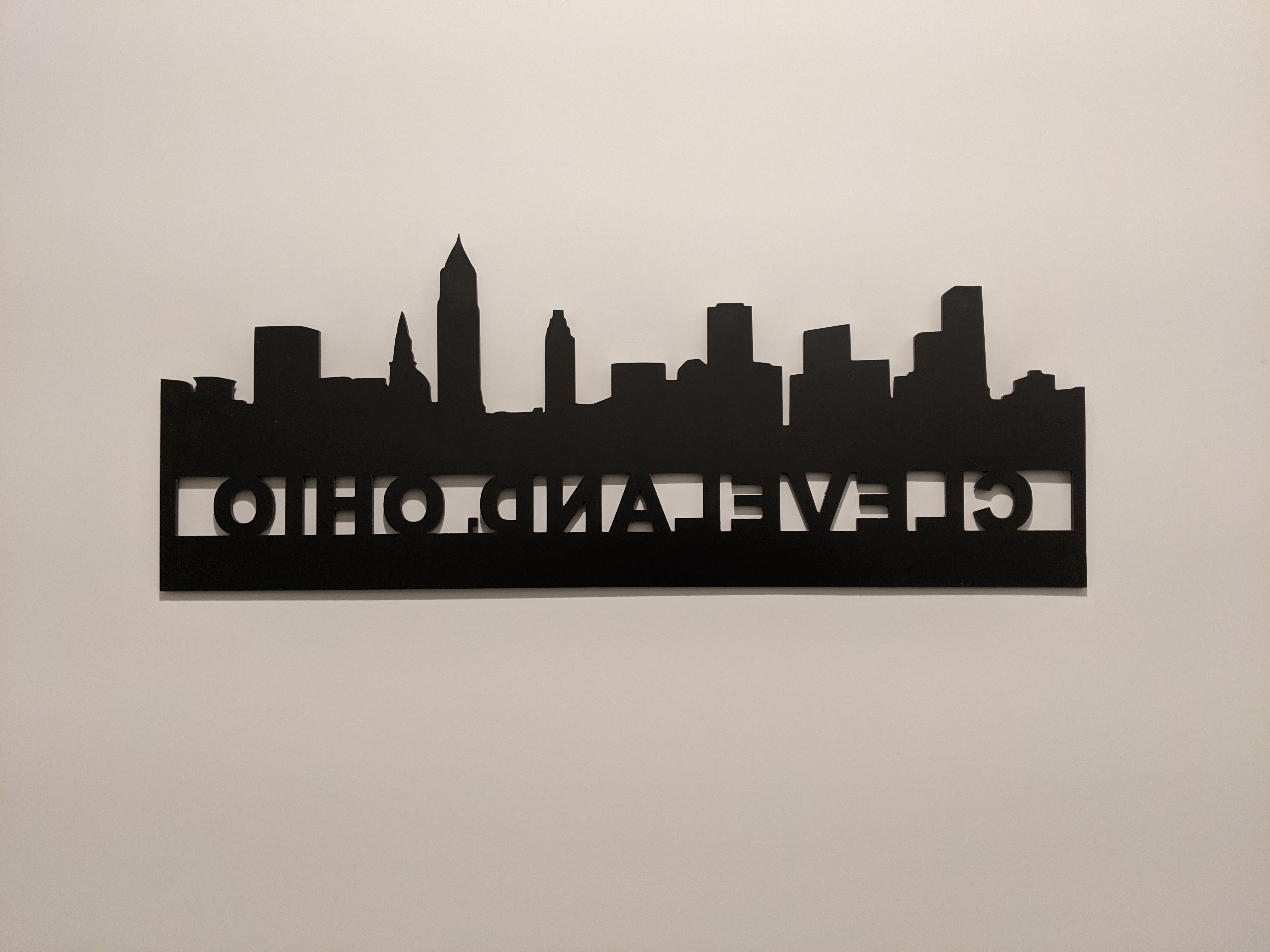
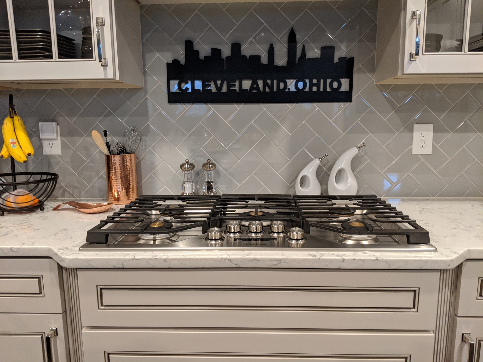
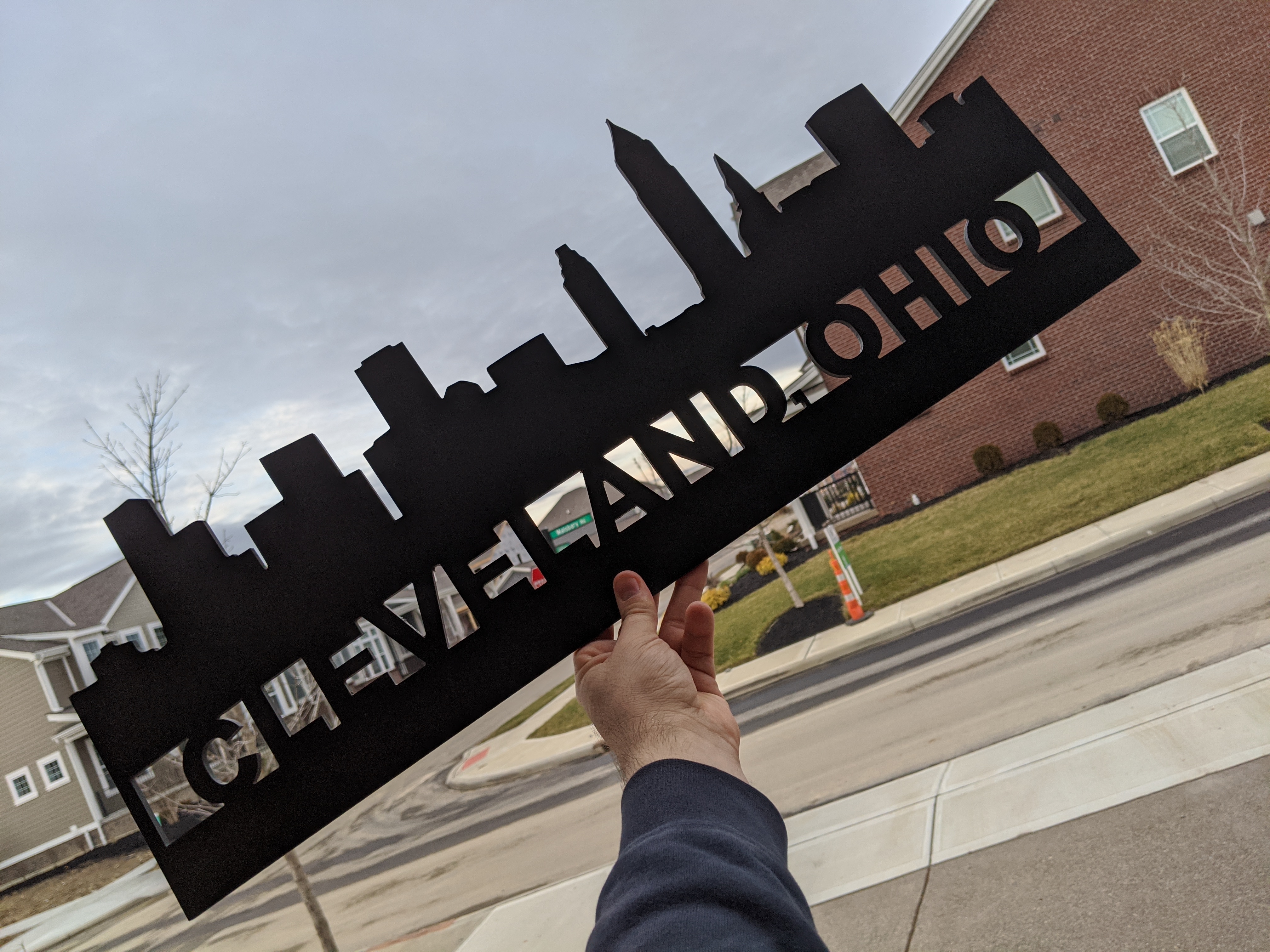
Ultimately, I went with something I meant to make for my brother (recently got a new house) that I knew he’d want but also knew HIS wife wouldn’t have a spot.
We’re from Cleveland.
Designed in Inkscape and Fusion 360.
Cut from 1/4" black PVC.
Got it to him today and had him take some “artsy” pics for me. He’s an @$$, so here’s what I got.


Fusion File
I was messing with making it bigger, so the file is set for a tiled cut. The completed version is 30" across. I might do a 45" version, but I could fit an 8ft version through my XL!
10 Likes
@duexx: very inspiring entry thank you !
Back in the day I too brought CC to its knees with a generated design, but CC has come a long way since then, so here’s to raising the bar with your design ! I’m sure @robgrz will be interested to send your file to the CC developers to have a look and see how they could better manage huge numbers of vectors.
@neilferreri this makes me wish I had space for an XL or XXL, so I could move beyond trivets and coasters, and REALLY invade friends and family homes with large signs 
3 Likes
I actually have a sketchbook design for a case for a compound bow which will be cut out of tiny scraps on my Nomad — just machine suitable components and assemble for arbitrarily large projects.
1 Like
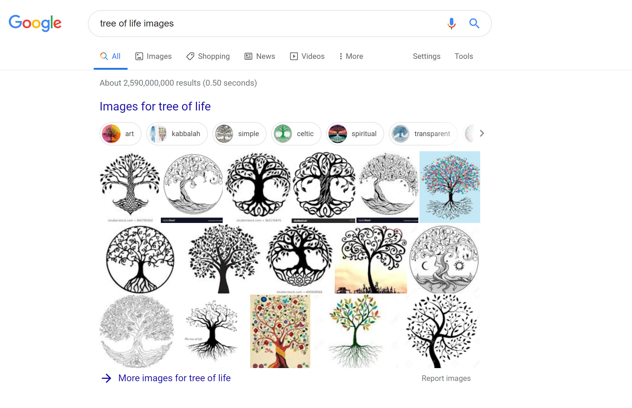
Ok I figured I have no excuse for this challenge this time with the extended dates. My first problem of course was finding inspiration of what to make…I googled “Tree of life” and settled on one that I liked. Seeing how it was circular for the most part , I started to wonder - how to incorporate into a panel. I figured that would resolved later on its own…
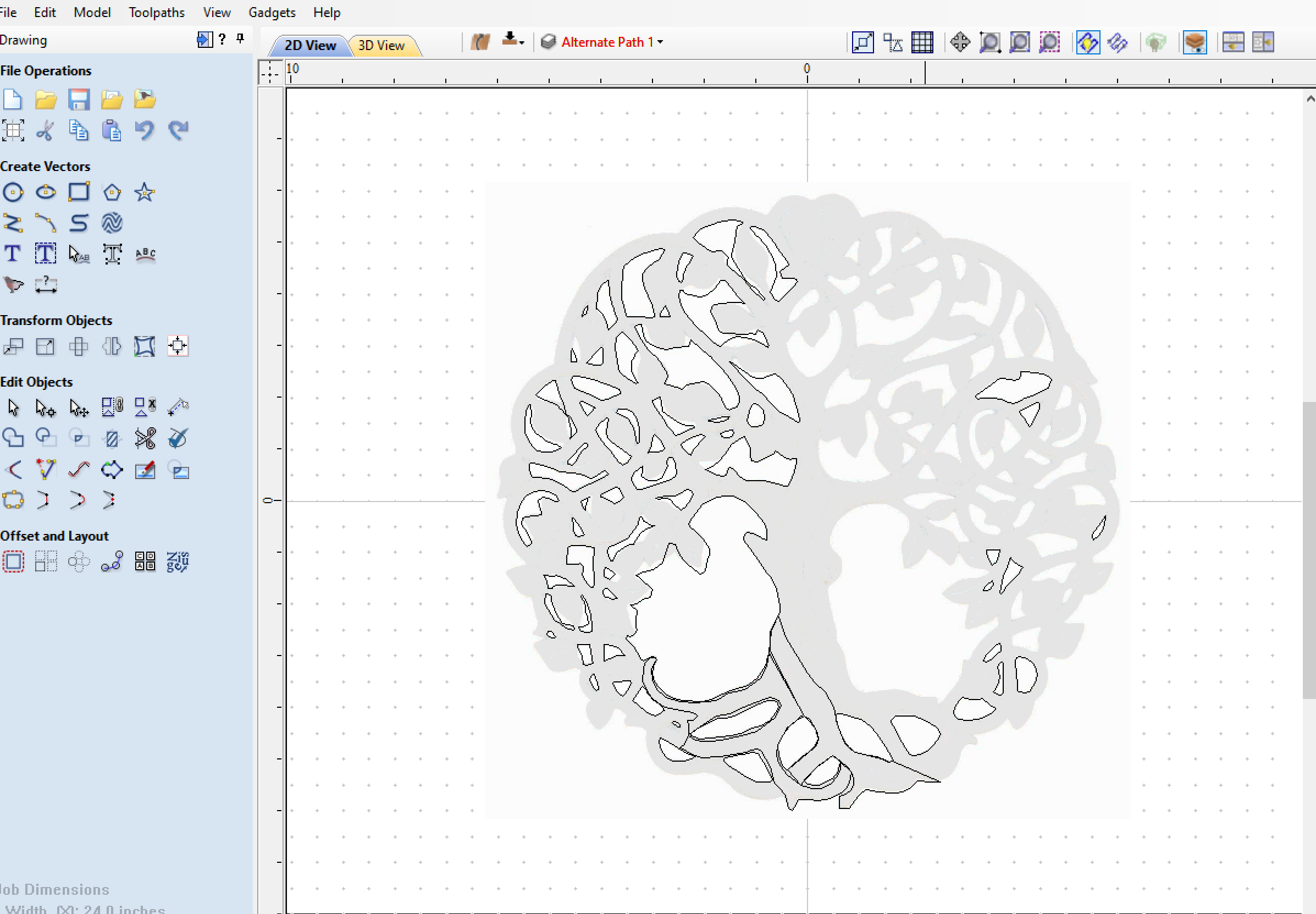
First began by tracing the main outlines of the tree,roots, branches and leaves.
next step was giving it some 3D images. So i went to thingiverse and search for leaves.
I found one i liked and imported into the project…and made approx 70 more instances of the leaf. Copied/rotated/scaled and placed all around.

After that I tried to give the tree some bark texture but quickly gave up on that idea since I couldnt get a decent result with the toolpaths…you can see I just left the lines in the main center part of the tree in the design.
Next I started to give the tree and branches some ‘bump’ along the components. This worked mostly on the bigger lower areas of the tree , but did not appear so good on the branches above. You can see this in a later photo below.
Once the layout was done it was time to start with the tool paths.
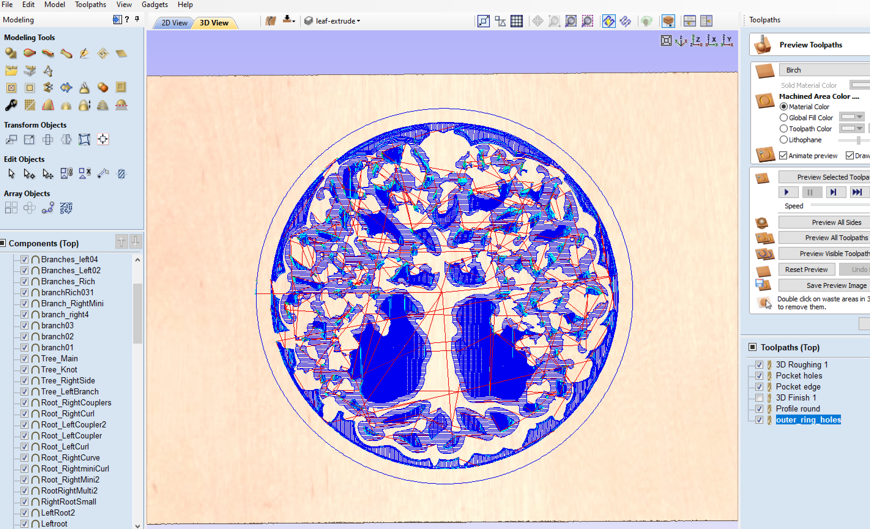
Originally exported all tool paths to two files both using 1/8" Mills so only a single tool change was required. #101 .125 Ball Cutter & #102 .125 Flat Cutter
Next was time to start cutting…

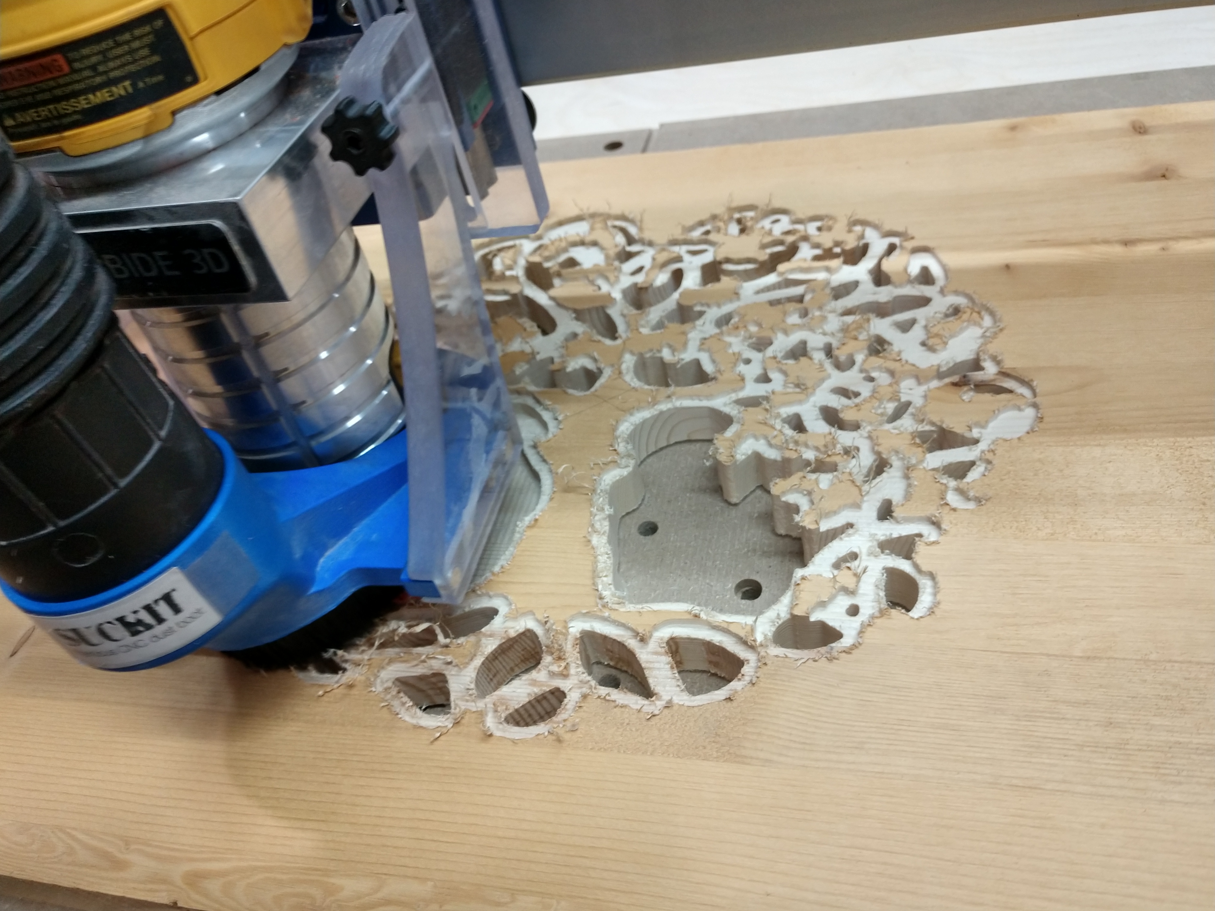
Ended up with this . Seeing it live in front of me and not the screen I could tell I was not happy. I was way to conservative and needed to remove a lot more material around the outer perimeter of the tree as it needed to be more “see through”

Went back and edited some splines to create some new objects, which of course leads to some new tools paths. I ended up with one more file to run but you could do all the roughing in 1 file 
cleaned up edges and added some color. Really just a proof of concept on test Pine 3/4" that is very dry!! Approx 16"x16" square
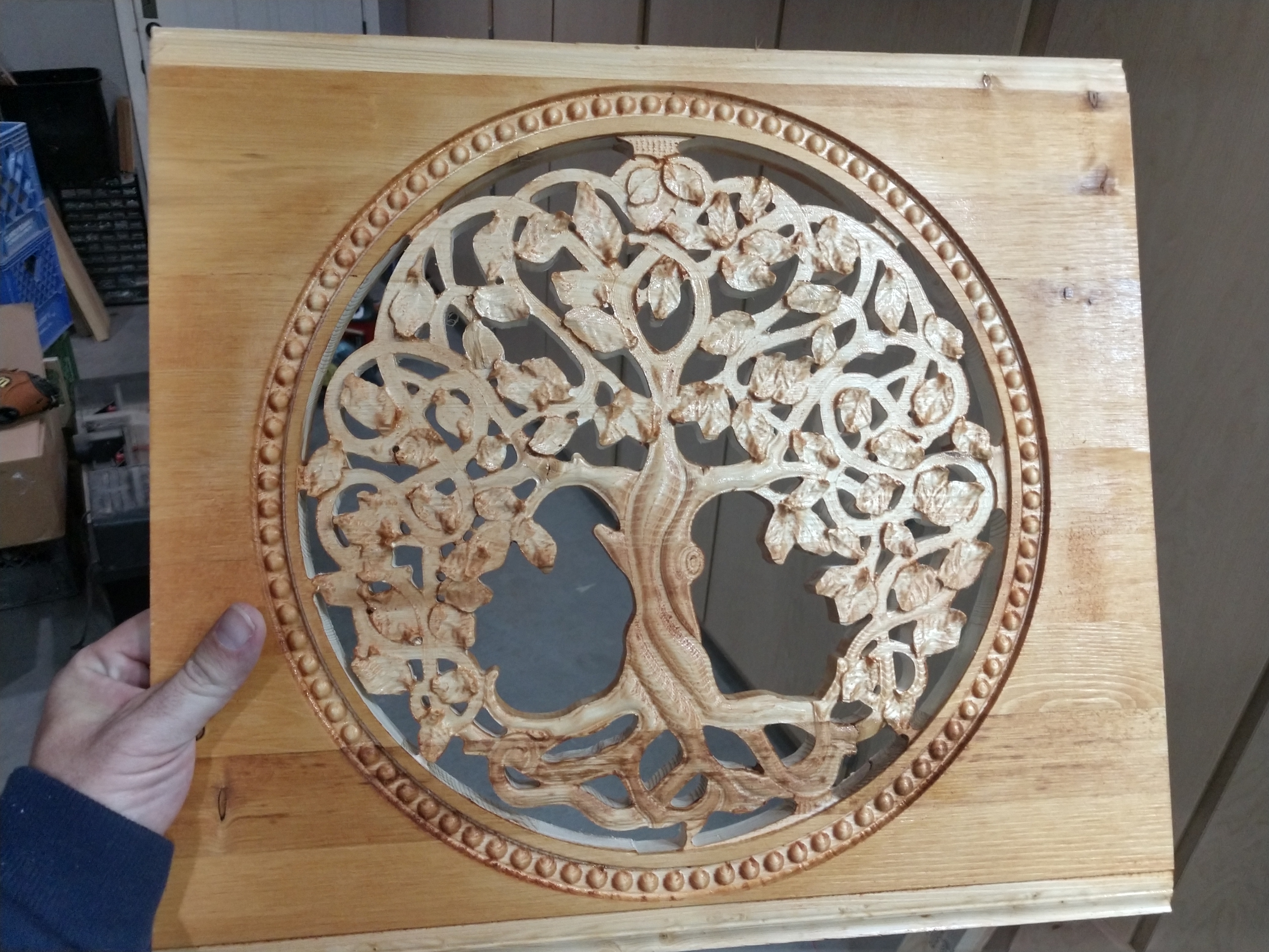
In this final image the smooth branches dont have any depth as I mentioned above. I modeled but did not appear in the end result. I ran out of time to google and needed to start cutting, as I suspect it has to do with limit planes which I am still learning and this is a great opportunity to expand my knowledge in this area. If that does fix the branches 3D contour, I presume I need to go back and adjust all the height of all the leaves individually to accommodate the new depth of the tree model and limit planes. And recalculate tool paths.
7 Likes
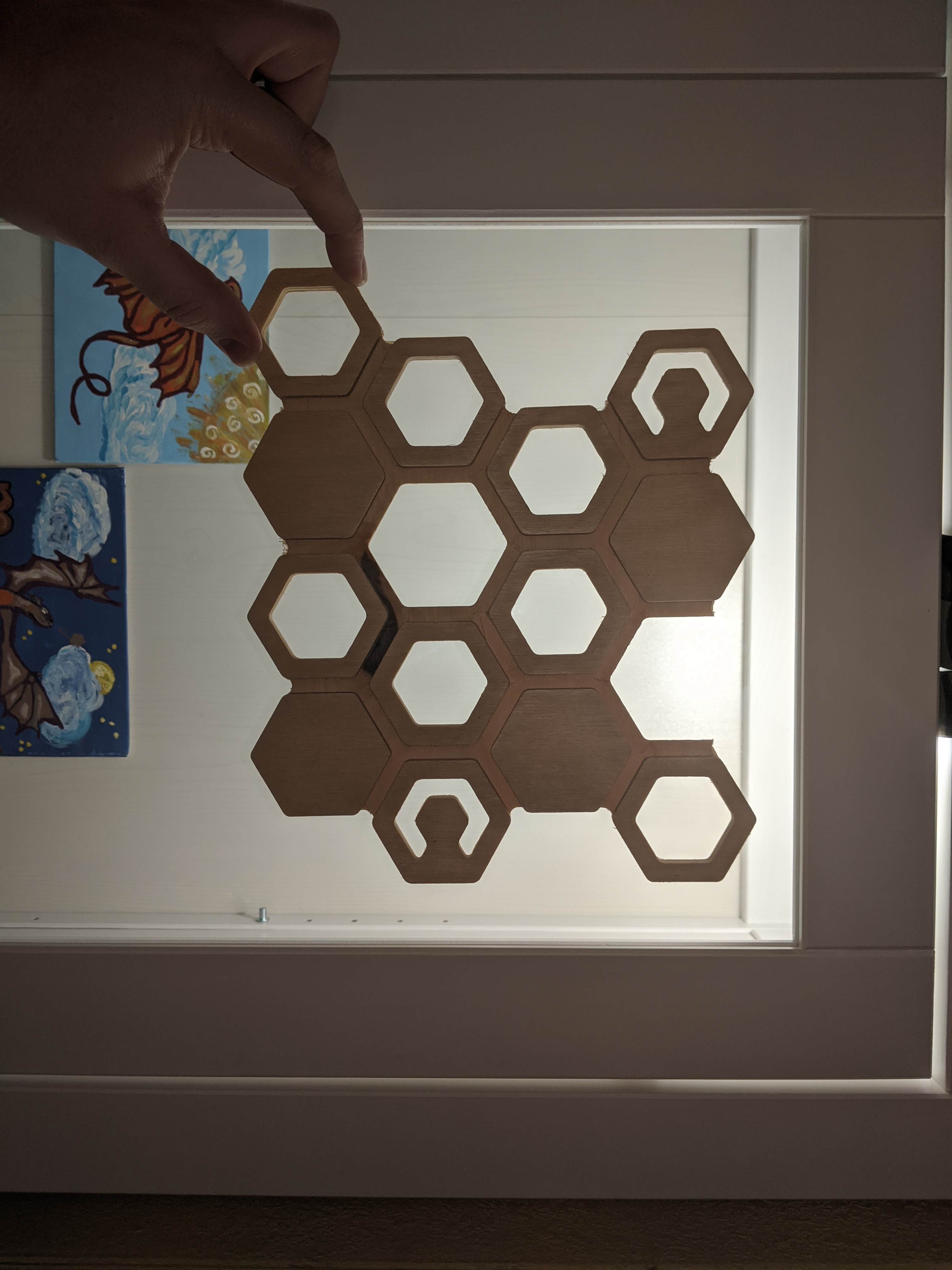
Did someone ask for hexagons and blatant pandering? Then I have the project for you! This is an idea I have had floating in my head to add a little flair to my upcoming shapeoko xxl enclosure. It is based on the Carbide 3D logo with the goal to incorporate the different dimensions as a little interesting visual effects
Step 1 import image of Carbide logo from the website and trace in Fusion 360

Step 2 Make my computer attempt suicide by meltdown. I have 6 gigs of slow ddr3 RAM from 2012, manipulating a sketch with 60+ fully defined hexagons with internal features is an effort in frustration and character growth.
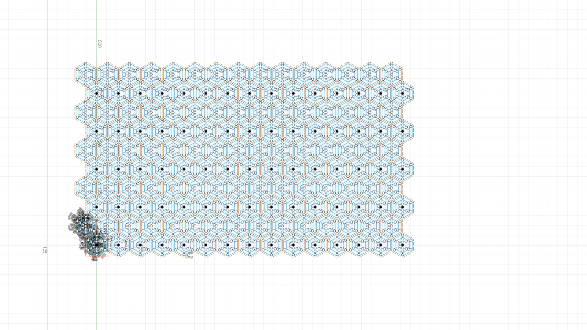
Once you have all of the hexagons I could play with which features I would extrude. I had the option to hollow the entire hexagon, a C a la carbide logo or a smaller inset hexagon with the same size as the C.

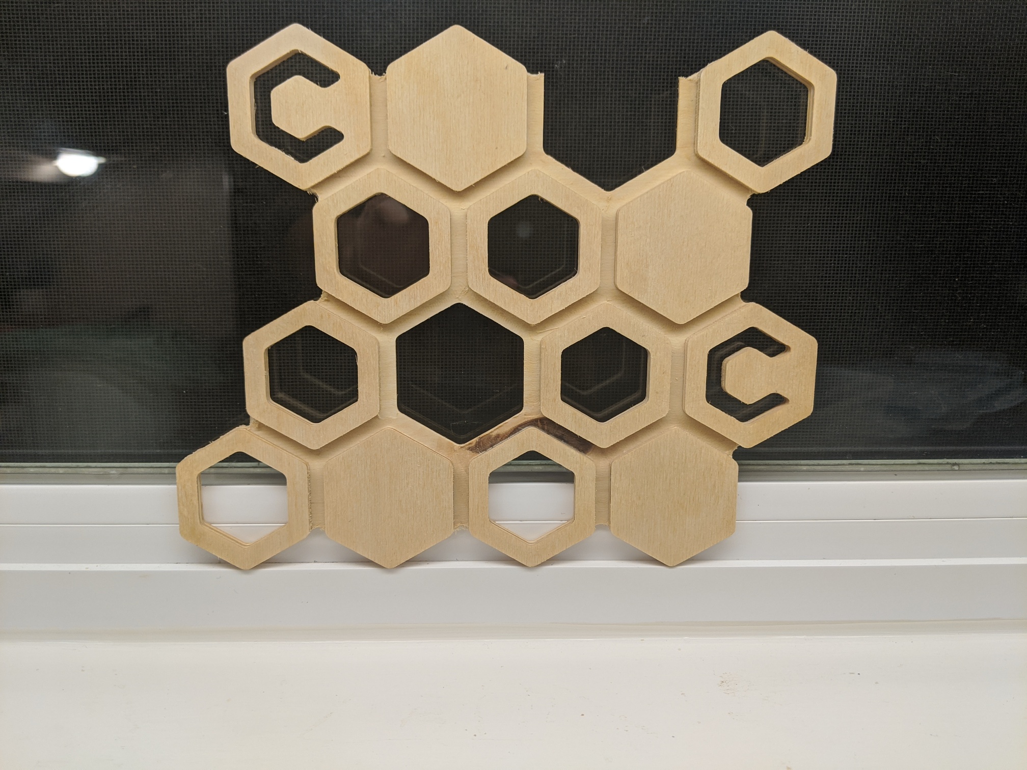
I then brought them to the XXL using a cheap no name 1/8 compression bit from amazon. I played with differing parameters but my best cuts in baltic birch plywood used a couple of operations to do the whole cut
- 2d contour for inner feature, DOC 2mm to bite in enough for the compression bit to do its magic. Tabs only on the hexagons, the C shapes did not have enough residual to worry about.
- full DOC adaptive with no stock to leave run at 3 on the carbide create compact router, 45 ipm. Probably could have run it faster
- 2D contour for the outer profile, DOC 2mm again for the compression bit. I did not attach tabs on this one but instead ran it as a second op with a clamp added to the middle of the model before running the final contour.
Finally, I ended up with something I can’t wait to include on my enclosure.
Design files: cc comp design file.dxf (1021.5 KB) It wont let me upload the fusion file but you can access is here https://a360.co/39uHRCv
7 Likes
@Rafi - That’s absolutely gorgeous! My wife would love it. I tried downloading your file but get a message from Dropbox saying “.zip files are supported but something went wrong”. Any chance you could repost or send the file directly to me?
Thanks
1 Like
Thank you Stan, Would be happy to fix the shared download link when i get home tonight. Currently at work and my employer blocks access to all online cloud storage. FYI the file has native extension as such as per the screen shots since it was made using Vectric software. (Approx 90MB when uncompressed).
@Rafi - I was able to download and unzip the file, but I couldn’t open it in Aspire V9.519. And chance you could save it as an STL file and link it? Beautiful work and as an amateur with Aspire I have some appreciation for how much effort you’ve put into this, thanks!
1 Like
@mikeG Thank you for the kind words. I am running Aspire 10.019 which may explain why a lower 9.x version of Aspire can not open. I have exported to .stl for yourself and anyone else not using Vectric software. Here is the link for the .stl export:
@ctdodge Were you able to get the original zip containing the .crv3d Aspire file? Looks like @MikeG was able to download ok. If you still have problems, once you download the zip try renaming the .zip extension to .7z before you uncompress it. (I used 7zip which sometimes has better compression than standard ‘winzip’.) I have crappy internet at home and needed to reduce to original 90MB file as much as possible before upload.
Edit for @MikeG I see what you mean…Lowered the limit plane -0.15 and re-exported .stl verified all branches are now visible and showing contour like i had originally intended  here is an alternate link for new .stl
edit for @ctdodge They are there, try either moving or deleting the limit plane if you are using original Aspire file or use 2nd exported .stl from this post. I have deleted original .stl which was missing branches.
1 Like
@Rafi Yes, my lower version is the issue with opening the Aspire file. I was able to open the STL, but it’s missing the upper branches but the leaves are all there. I’m going to try working through that and will share the file if I’m able to. Keeping in mind that I’m a newbie, have you tried raising the shape height and lowering the base height? Thanks again for your efforts, good luck in contest #4!
1 Like
@Rafi - I finally got a chance to look at this and I see the same thing as MikeG, The leaves are all there but not the branches. I am running Vcarve Pro 10 so I don’t think it’s a version issue. Since you see the branches maybe it’s an Aspire vs Vcarve issue
I’m just not a software guy. What is the difference between Vcarve and Aspire?
@Rafi, the file looks great, I’m a bit surprised that I was able to spot this, but I was recently working with another STL and kept losing details similar to your experience. Finally traced it to this same issue. In any case, I’m glad it was helpful and I hope your next carve of this turns out as you intended.
@MikeG - were you able to get all the details in that file? All the branches for me don’t show. Of course, it’s very possible (likely) that I just don’t know what I’m doing as I just started playing around with 3D carving
@ctdodge - yes, albeit I’m using Aspire. I had to lower the STL file into the material until all of the detail showed. I haven’t tried with Carbide Create as I only have the unpaid version and don’t think it will show the 3D detail of an STL, but I have imported STLs for tracing previously. Someone’s on the boards will certainly know the answer to that question though.
I’m gluing up a large enough piece to cut this, hopefully in the next few days and I’ll post a picture when complete.