Nice ! 60 deg V-bit ?
Can you please edit your entry to include the design file / info ?
We want to hear about your feeds and speeds, bit(s) you used, whether it was CC advanced v-carving of Vectric V-carve or any other CAM program, etc…
2 Likes
Yes I will edit my post tonight.
1 Like
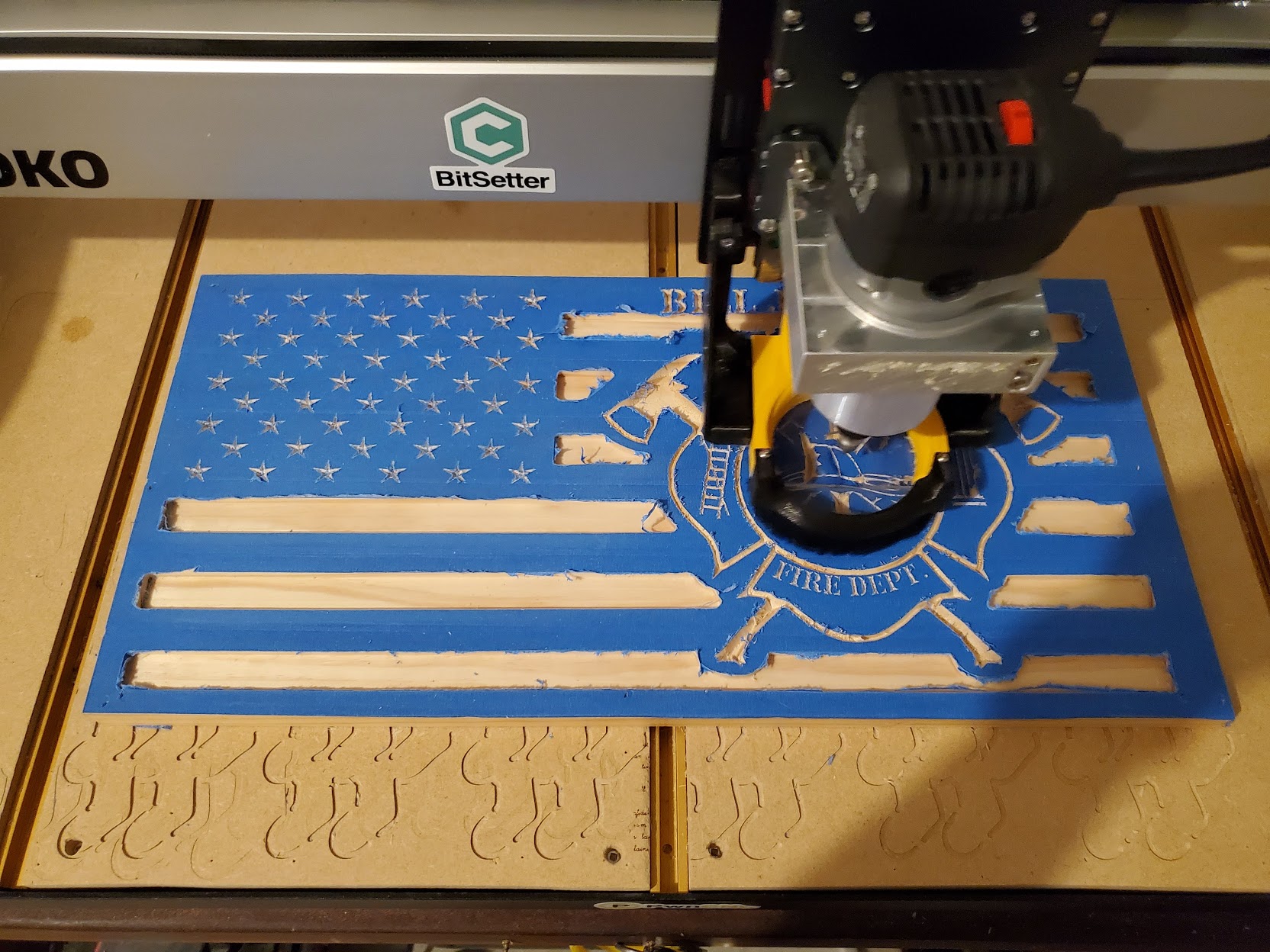
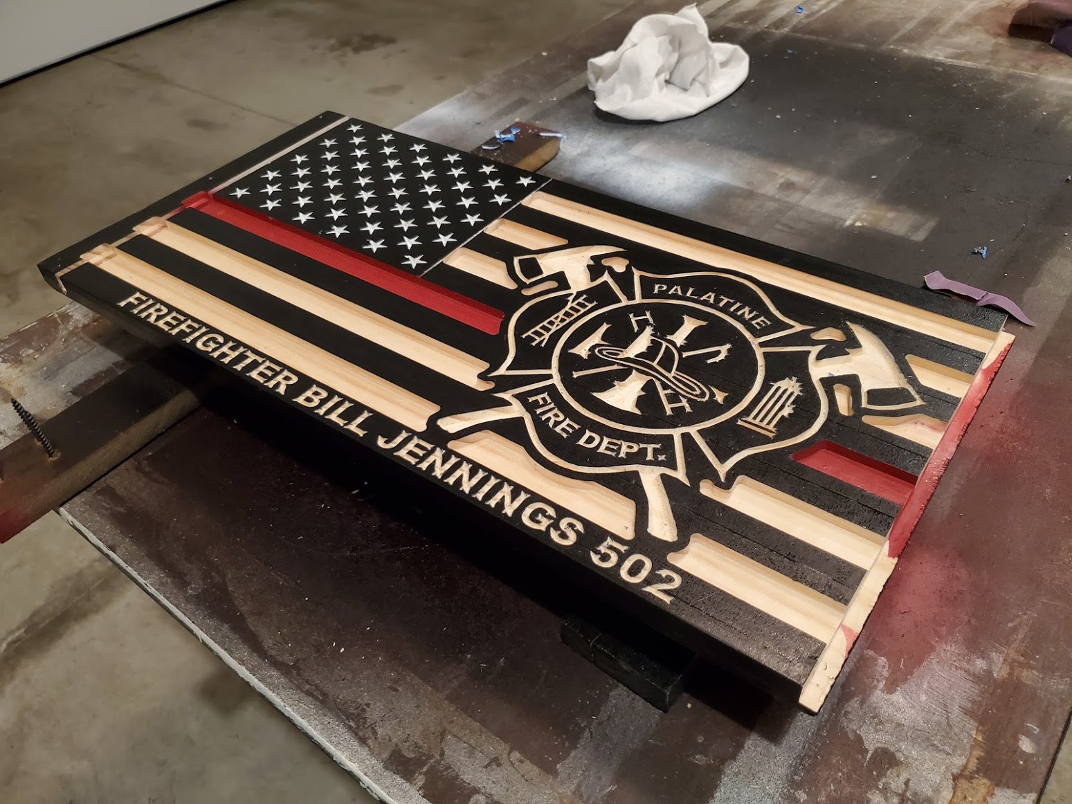
This is an older project, one of the first i did on the machine. My Father in law is a retired fireman, and i have been seeing these things everywhere… but they ranged from $75 to $300… so why not buy a CNC and do it yourself right? 
11.25 x 23 x .7 thick pine, v carved stars, text and logo. 60 degree half inch v bit again (only V i have currently).
i was a bit more conservative at this one… 75IPM, about .0625 depth of cut. 11 INCH FIRE FLAG FIXED DIMENSIONS - Copy.dxf (788.7 KB)
10 Likes
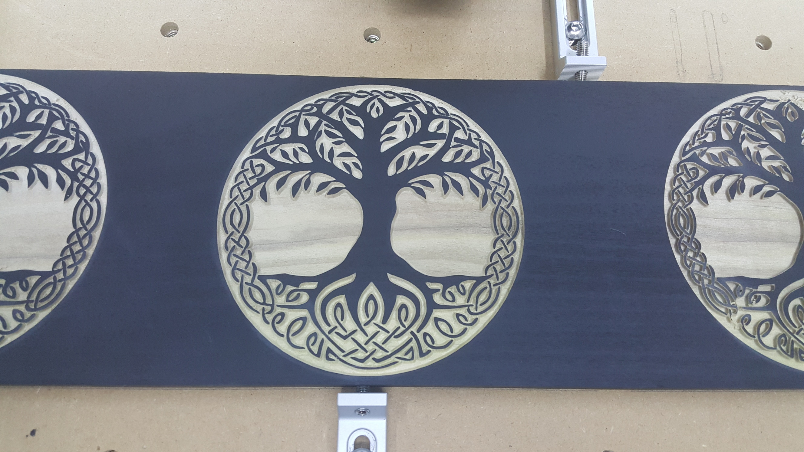
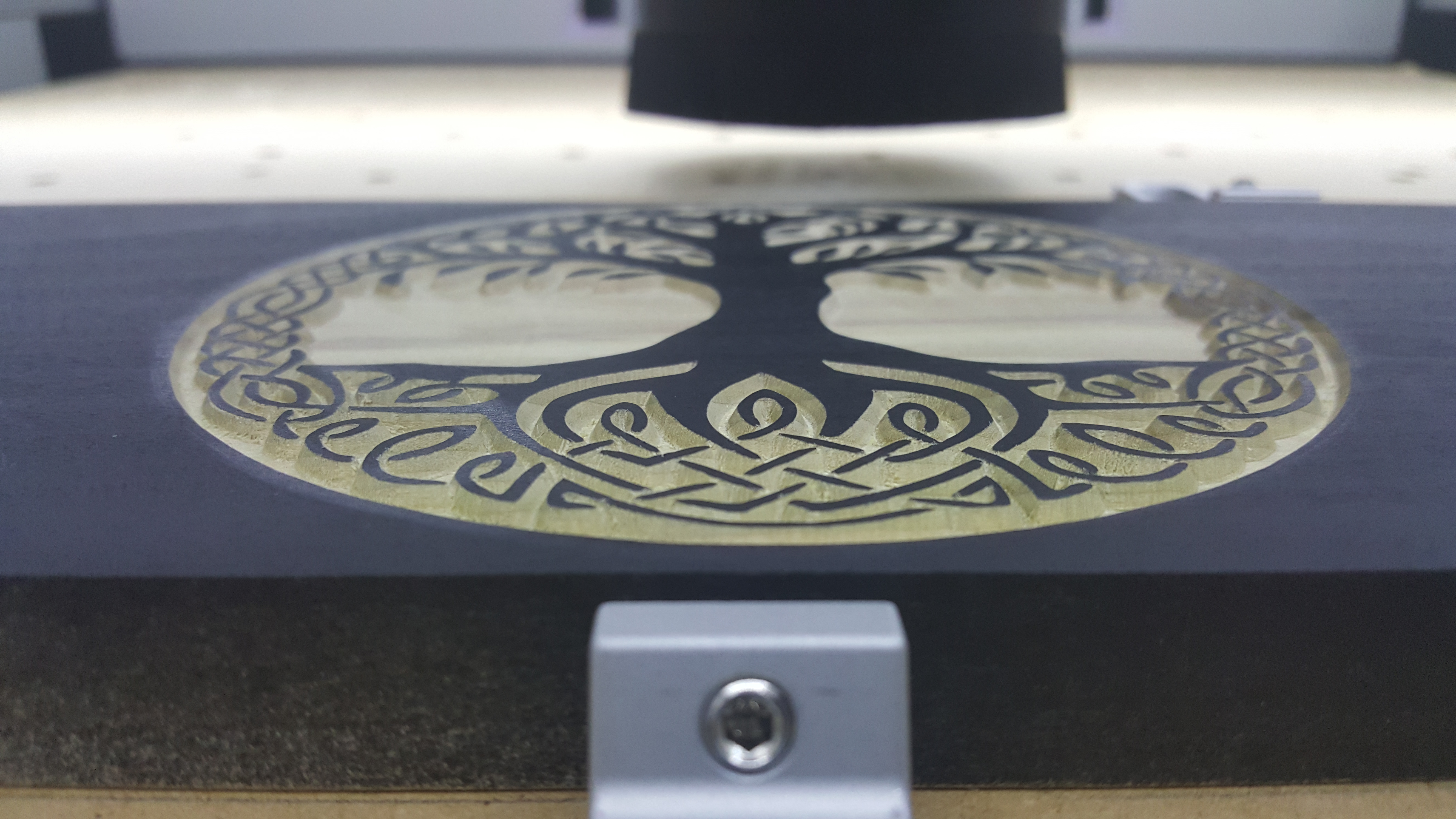
Decided to play around with the new advanced vcarving in carbide create. I’ll get my full submission with cut file and info posted later today.
Edit: I removed the cut file. Adding more tool path applicable pictures soon
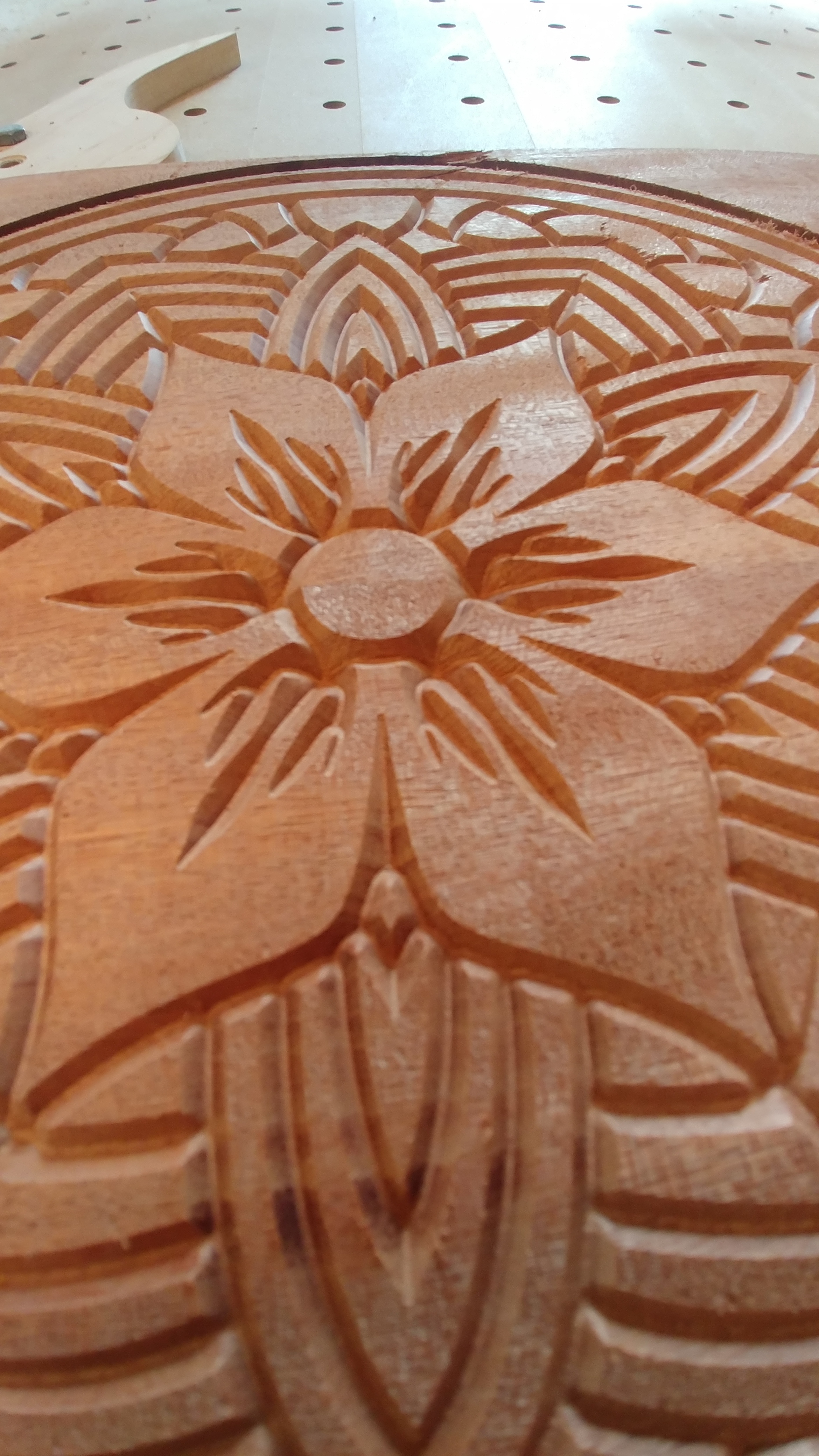
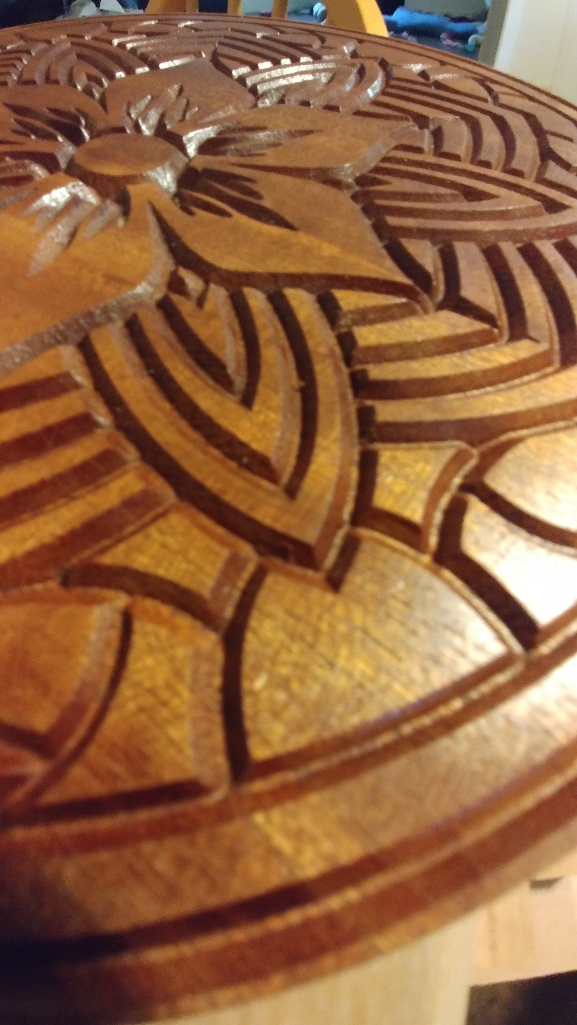
Total diameter is 5.25"
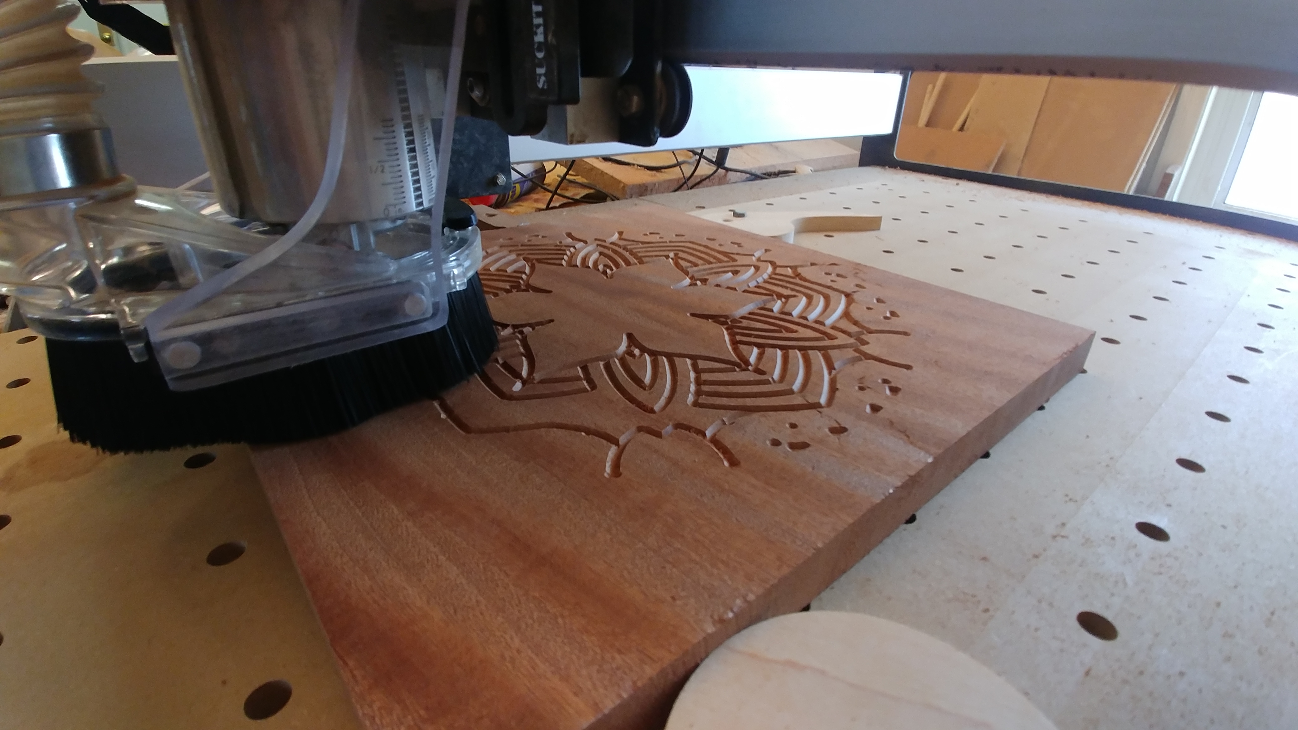
The image was pulled into Inkscape and traced, with a little hopping back and forth between boolean and node editing in both CC and Inkscape (multiple node selection in CC is tedious). I haven’t used ANY design software since high school/early college days and I am by no means doing it “correctly” or efficiently. I am sure most people would gasp at some of my design/cut files.
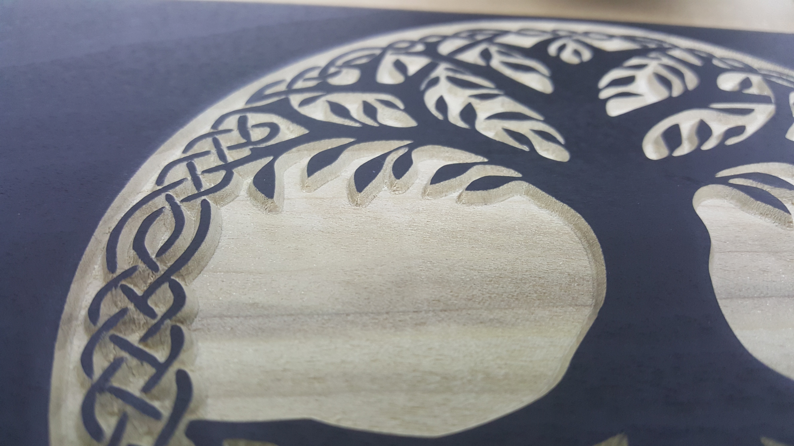
I used the Advance VCarve toolpath with a 1/32" 4 flute upcut endmill for the pocket clearing, and an Amana #45707 60 degree “zero point” vbit. In terms of getting clean cuts with the vbit, I crank the depth of cut per pass way back to somewhere in the realm of .030"-.060" (this is mostly to prevent major chipping of fine details) with my feed and plunge rate set to 30/15 @ 25k rpm. From there I can play with the feed overrides to get it sounding and looking just right for each individual piece of wood, at times being able to run it at an almost 200% override, sometimes down to 70%. This is a holdover from my settings for regular vcarving of letters and numbers which seem to work just fine considering I cut mostly poplar and pine/fir which is notorious for stringy/fuzzy/chipout crap. I should also add that I set the stepover of my vbit to .001" for the advanved vcarve clearing due to the “zero point” tip.
Here is the setup and f&S for the 1/32" bit:
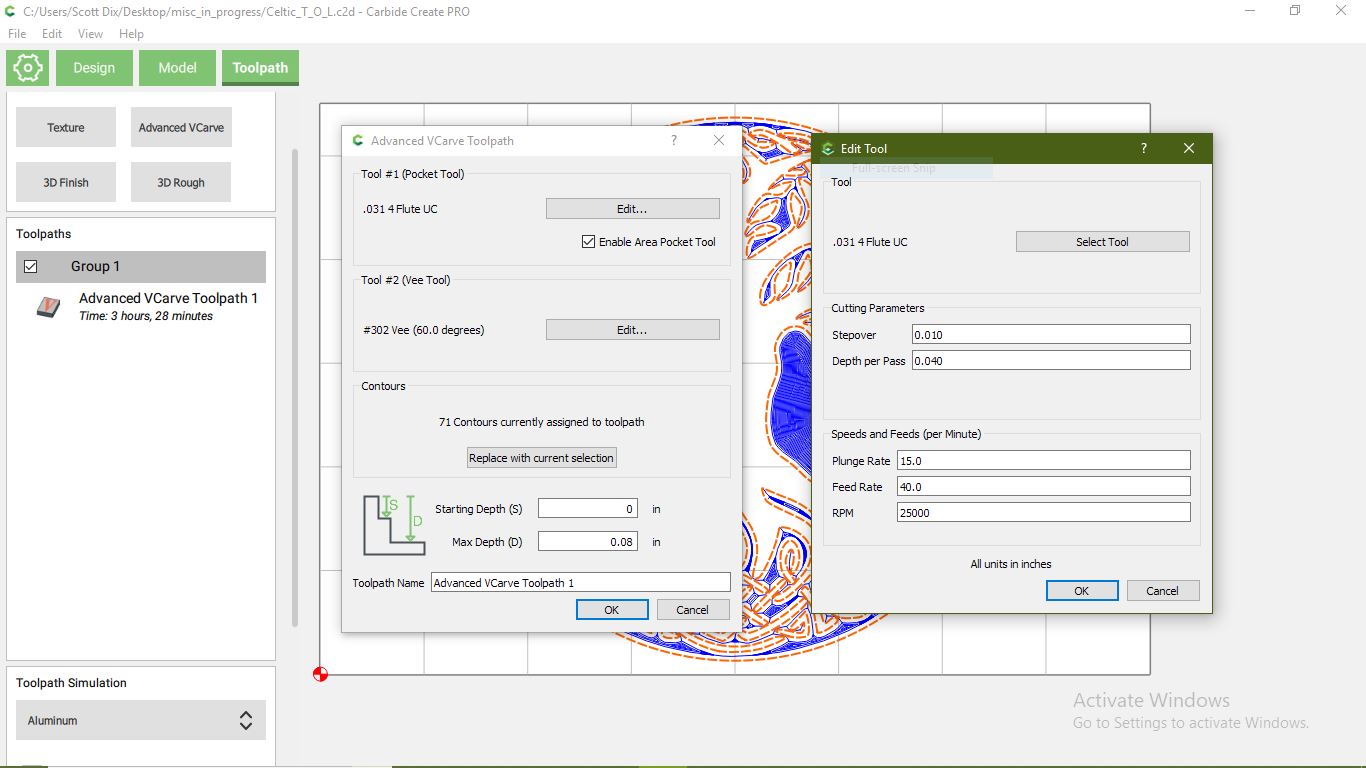
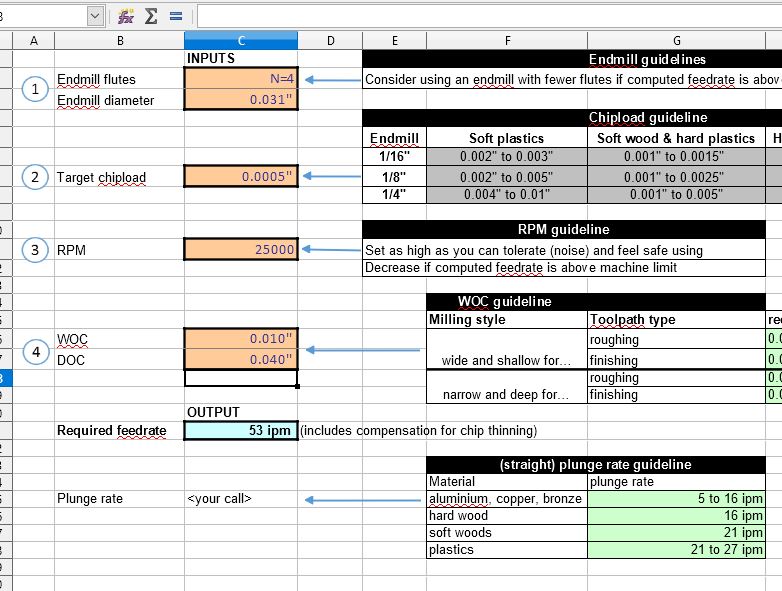
A .0005 chip load for a 1/32’ end mill may seem off, but it calls for a feed of 53 ipm according to the wonderful table and I set feed at 40 ipm. I will watch the first portion of the pocketing with the 1/32" bit and adjust the feed override accordingly depending on how the first pass pocket bottom looks like and how it sounds cutting through tight corners as the engagement of the tool “spikes.” If I am too busy to watch the first few minutes, I will slow it down to 80% override and keep the music down so I can listen, but don’t forget to reset your feed before starting the next tool. I have and an already aggressive cut pass @ 200% override can scare the bejeezus out of you and leave you scrambling for the emergency stop/feed hold.
Some of this may seem super conservative and/or “bad” for an endmill’s longevity, but what’s some extra wear on a bit vs. a sand free, finish ready commission that’s about to put money in your pocket or a gift that will put a huge smile on your friend/family member’s face?
The cut path loads with an estimated time of 3hr30min but it did not take nearly that long.
14 Likes
I’ll throw my hat into the ring.
I finished this wall hanging the other day. It is 11" by 11", cut out of Sapele.
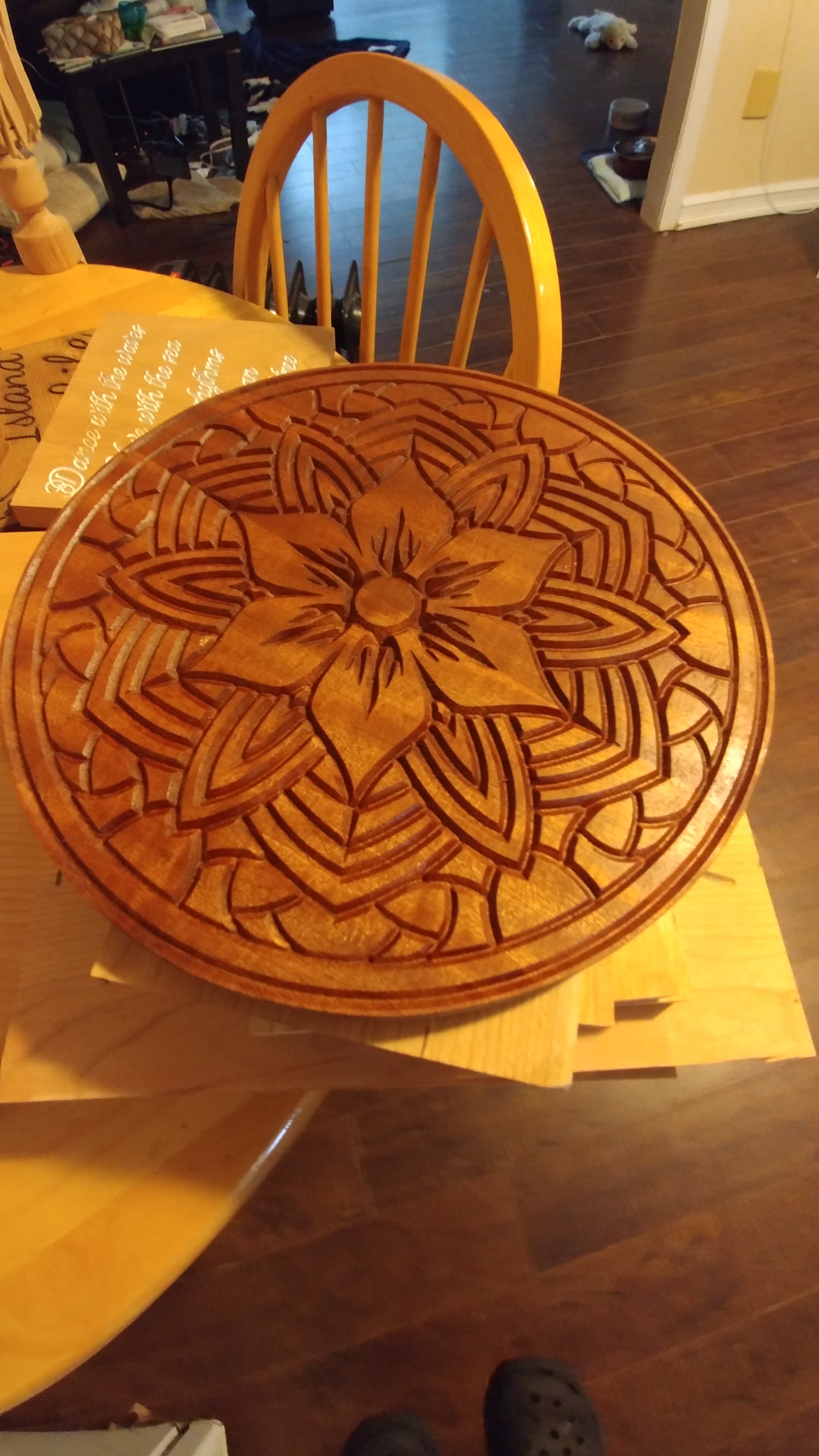
This was programmed in VCarve Pro using an Amana 45704 90 deg V-Bit. 18,000 RPM, 0.1" pass depth, 40 ipm. It was then profiled with an Amana 46315 0.25" Upcut Spiral bit. 18,000 RPM, 0.075" pass depth, 80 ipm.
The carve came out very clean, though I did edge up the RPM a bit to help deal with a few strings that were loosely attached to the base of the carves. It required basically no additional work, beyond sanding down to 180 grit on the surface, and then coating in matte spray lacquer.
I find the limited pass depth on VCarving to be very helpful. It means you often get a built in finishing pass, and reduces shocks of stress when a v bit has to try to hog out its full diameter after a quick plunge.
I bought the vectors for this project here: https://designbundles.net/pixaroma/4550-100-vector-mandala-ornaments#gtmList=30>mPos=8.
I can’t seem to upload the gcode or design file, as the extensions aren’t allowed. Also, since the vector is purchased under licence, so am hesitant to upload it.
Happy machining everyone.
12 Likes
Thanks for the link! Your project has sold me on those designs. Looks awesome!
Come on guys (and gals?), my V-carving craving has not quite been satisfied yet, and there’s still one week-end on the horizon to submit your entry !
Maybe V-carve adamantium to beat @Vince.Fab at his own game ? 
3 Likes
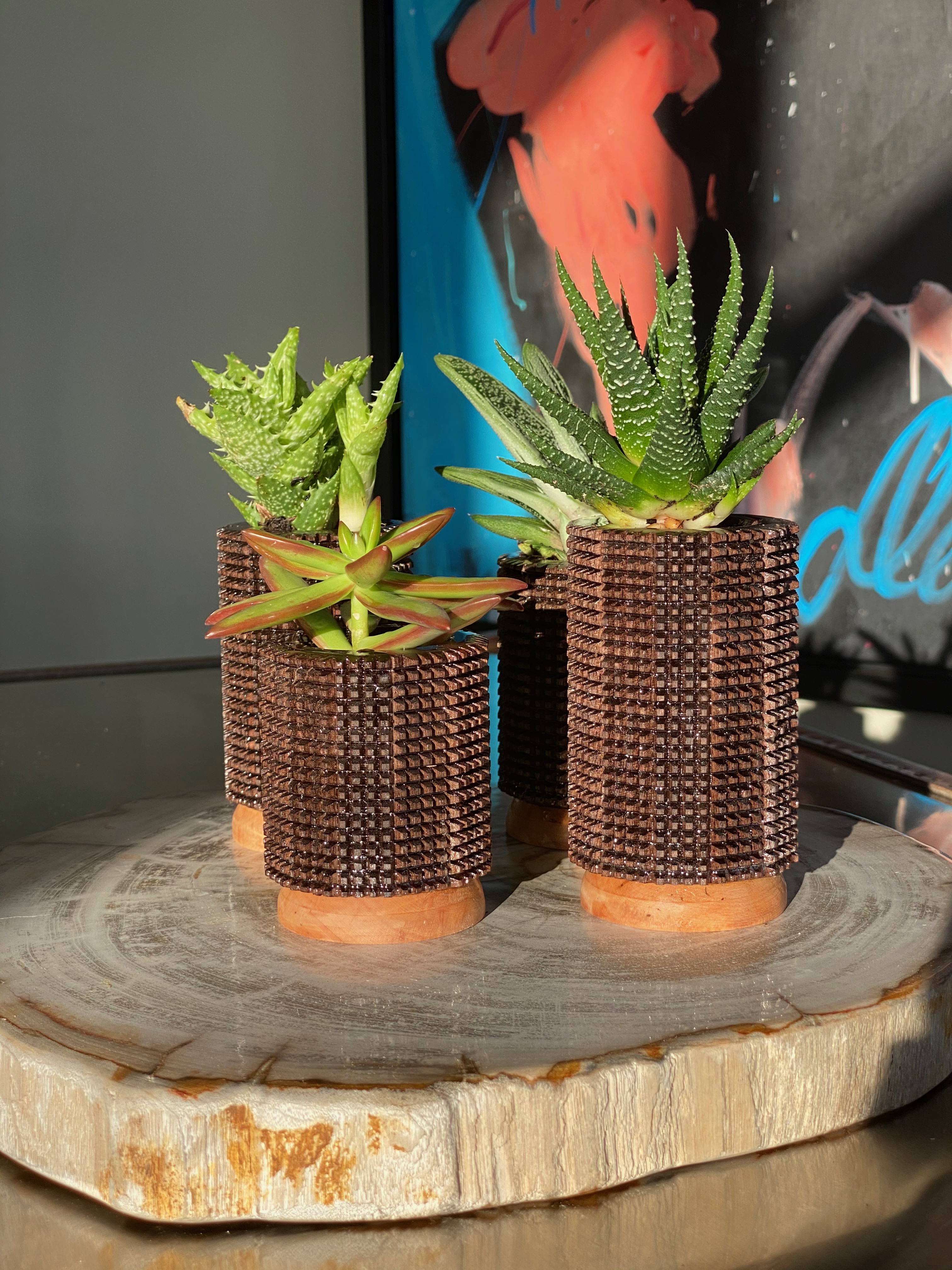
I had a lot of fun with this one; thank you to @Julien for these contests they really challenge me to push my creativity and what I think a 3 axis machine can do. Since buying my Shapoeko in Nov; I have never busted out my v-bits for any reason mainly because I loath the idea of making flags/signs, but also I’ve heard how woahfully inadequate Fusion360 is for v-carving. So my goals for this challenge were as such…
- Use V-bits to create a production product that would otherwise be time/effort/cost prohibitive using non-digital manufacturing.
- Use only Fusion360 to do it.
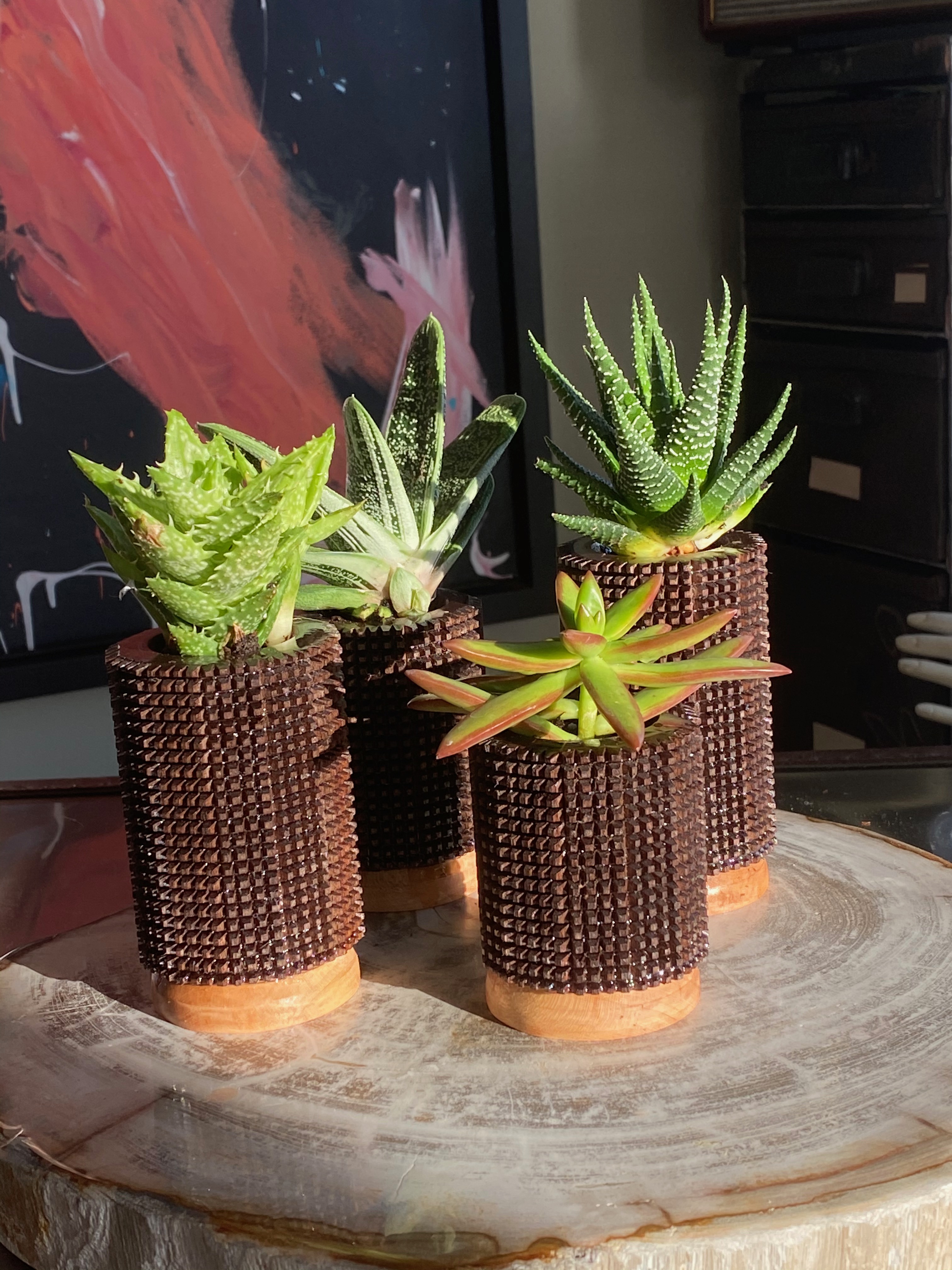
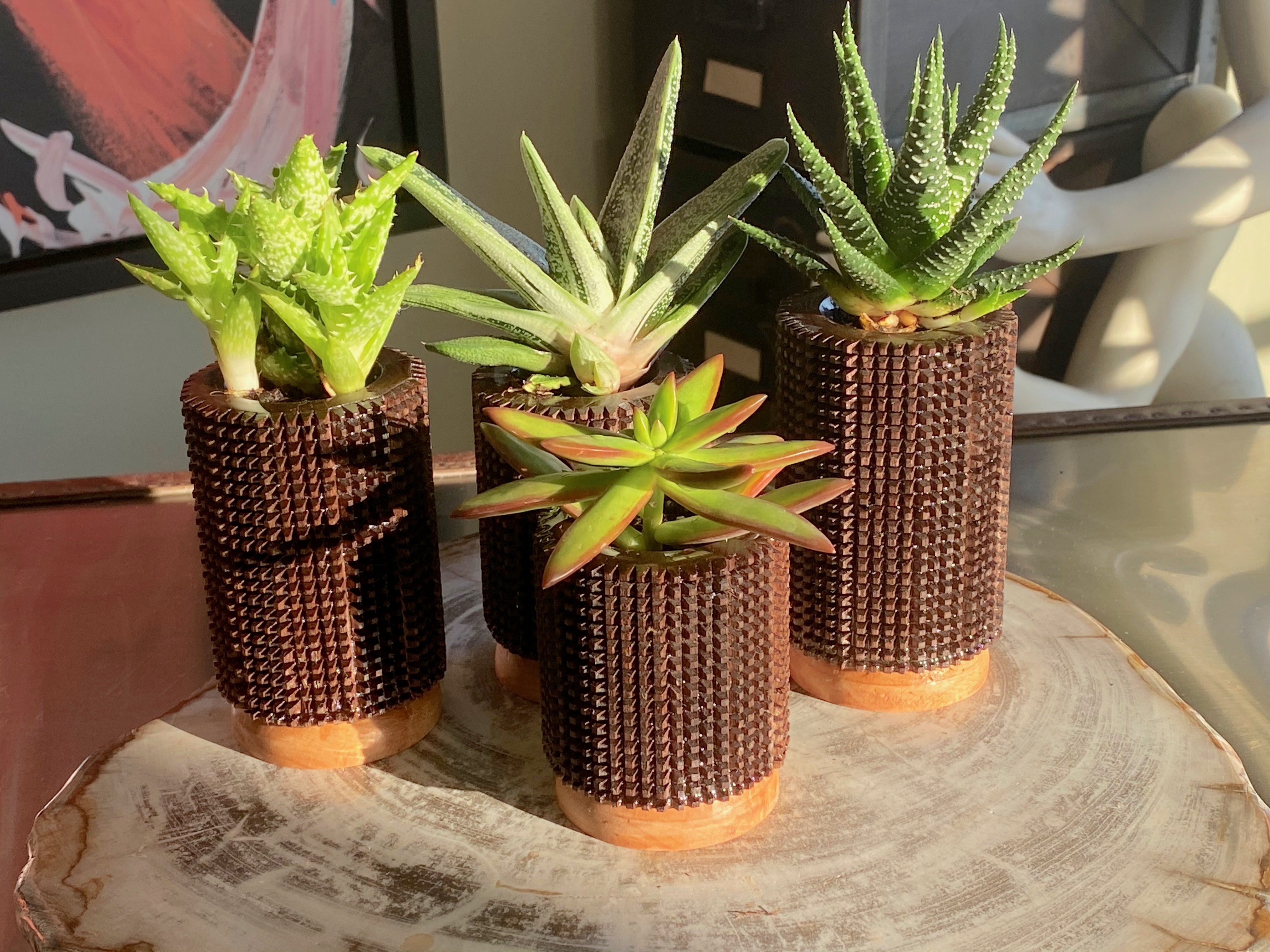
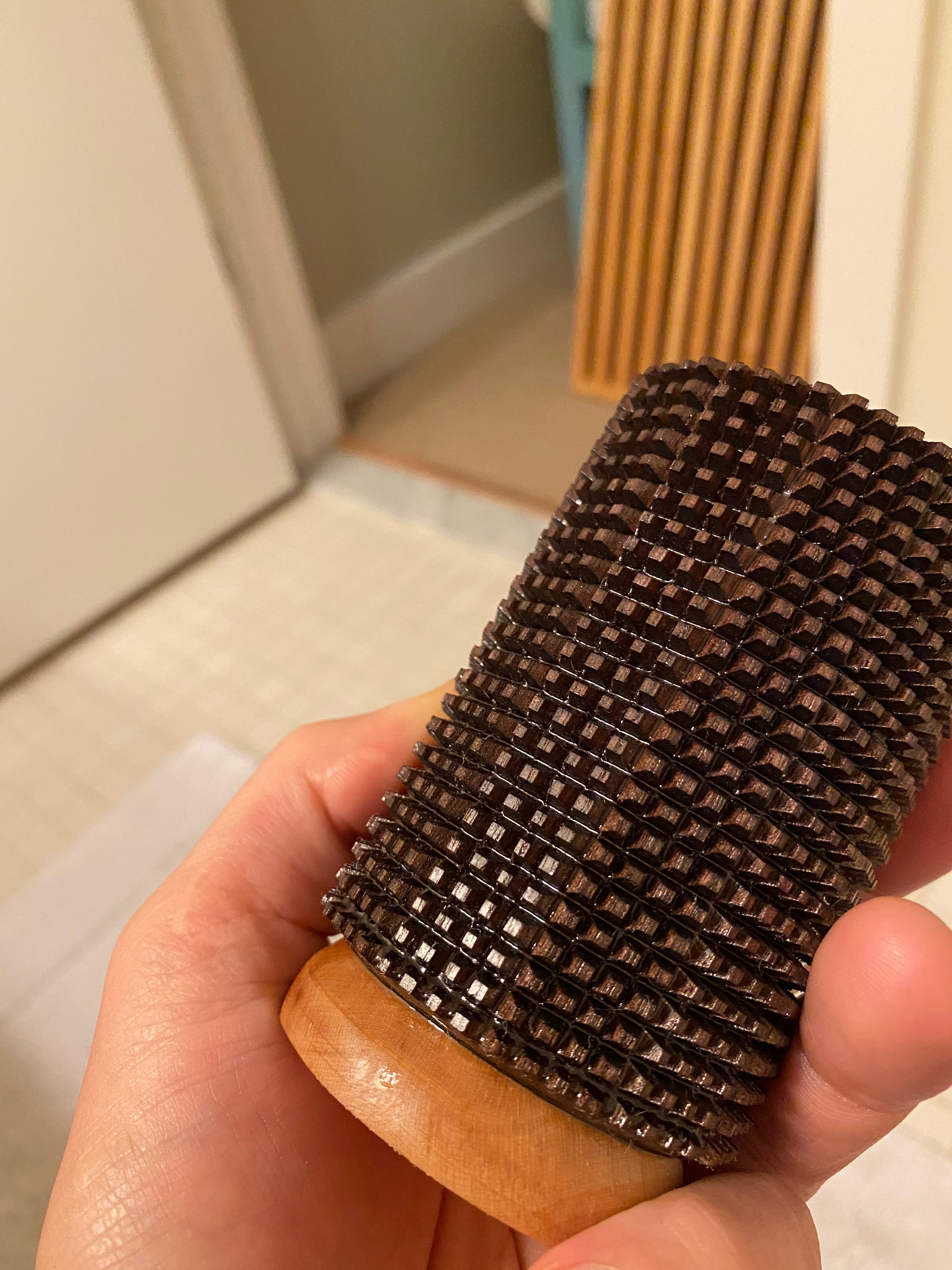
Final Product: (Knurled Succulent Planters):
Process:
-
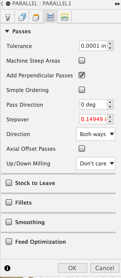
This item can be created entirely in the CAM environment created with parallel toolpaths and manually set stepover values. The “Design” environment is entirely pointless. You could make the exact same thing in the CAM environment by creating a custom “tapered” endmill in F360 then using manual stepover values to dictate the distance apart, and then using the Z offset feature in Setup to control for the depth of your v carves. For details on how to set this up watch this youtube video from 10mins-14mins: https://youtu.be/dSYQLpQhr9M?t=595
-
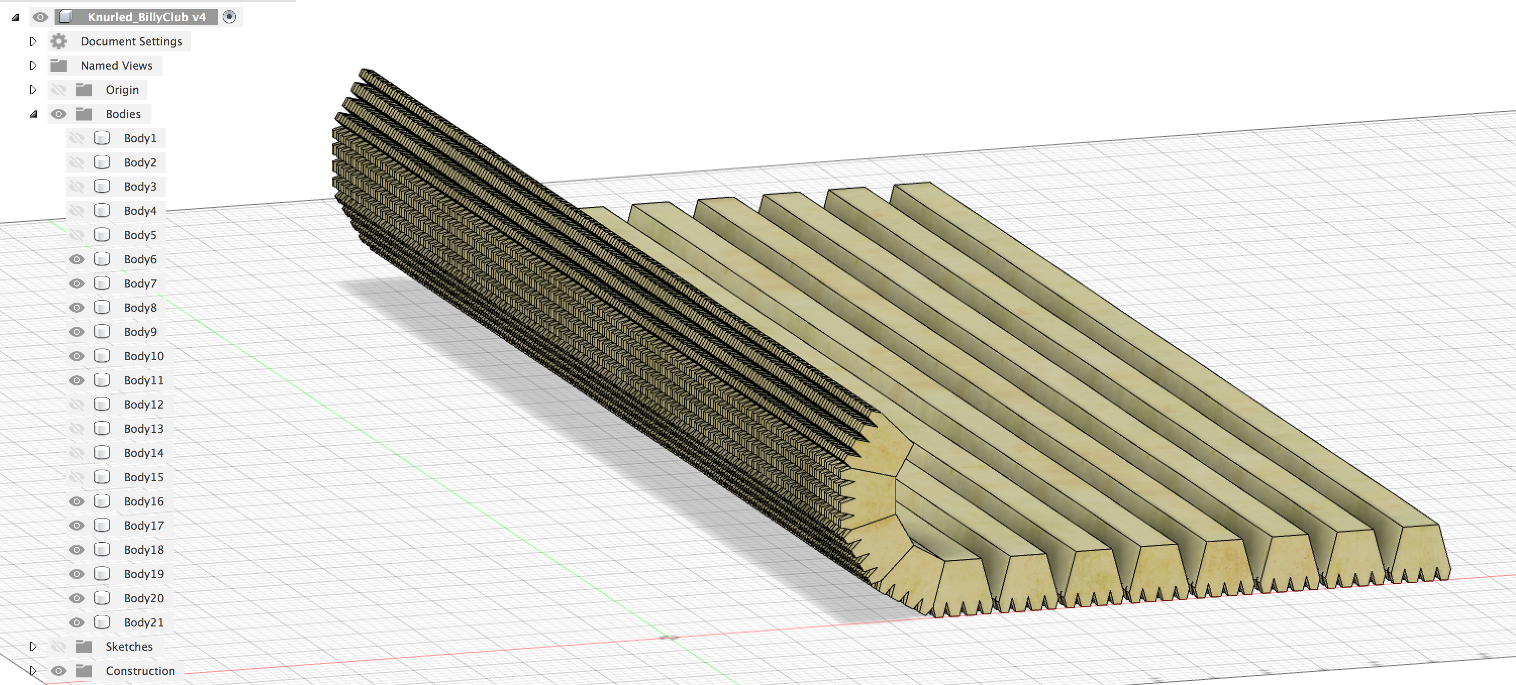
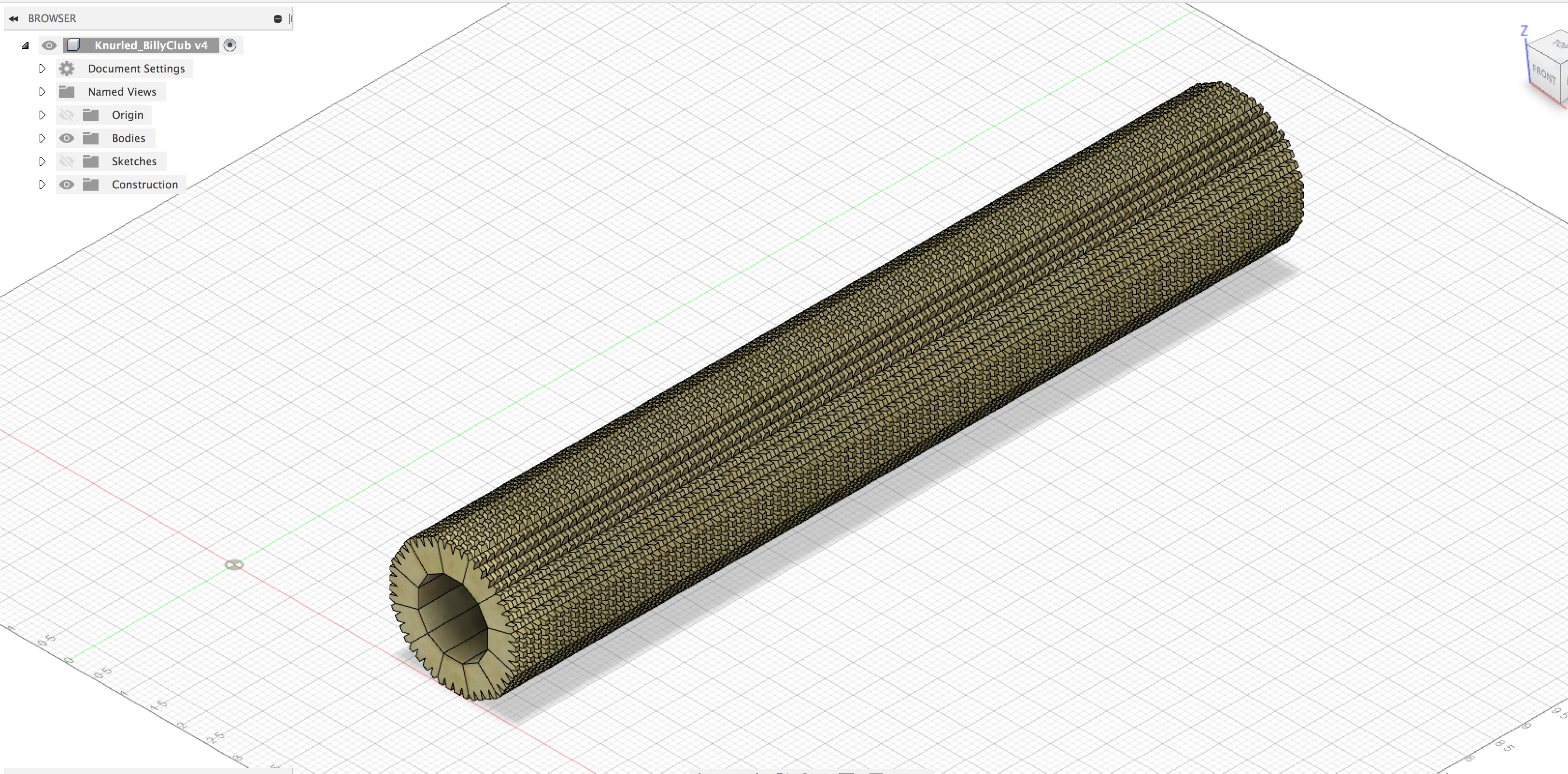
So why do I have a design file? I’m admittedly terrible at math/geometry, and I couldn’t for the life of me figure out what would be the final diameter of my cylinder based on X width of “Kit-Kat Bars”. So I spent a good bit of trail and error in F360 before I arrived at it would take 12qty 30degree kit-kat bars each being separated by .14949" V-carves walls to get to a cylinder that is about 2.5" in diameter. Kind ask to @WillAdams to provide a formula here that would allow me to parametrically figure out the depth and stepover values based on Y degree of V bit and X length of kitkat.
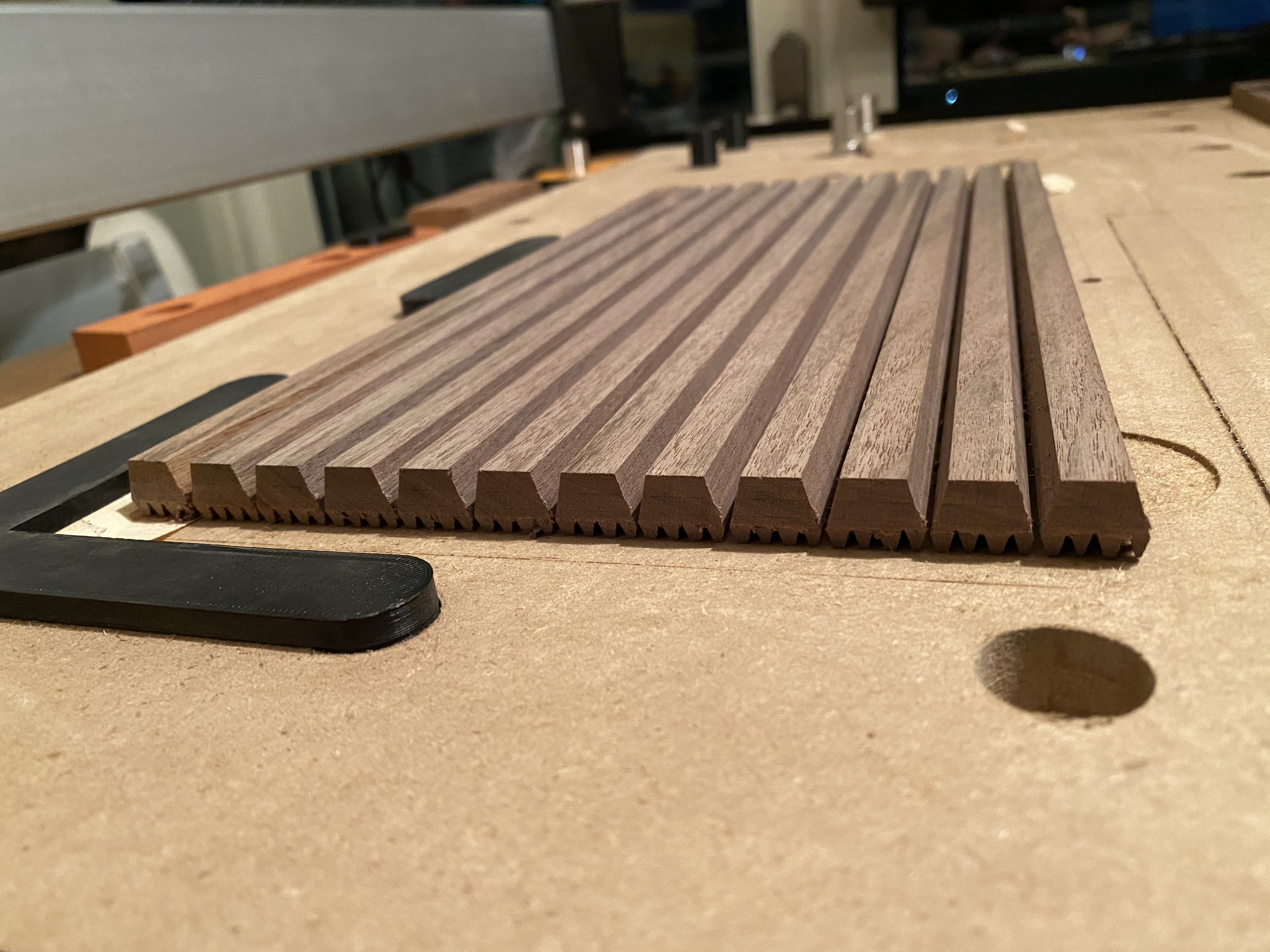
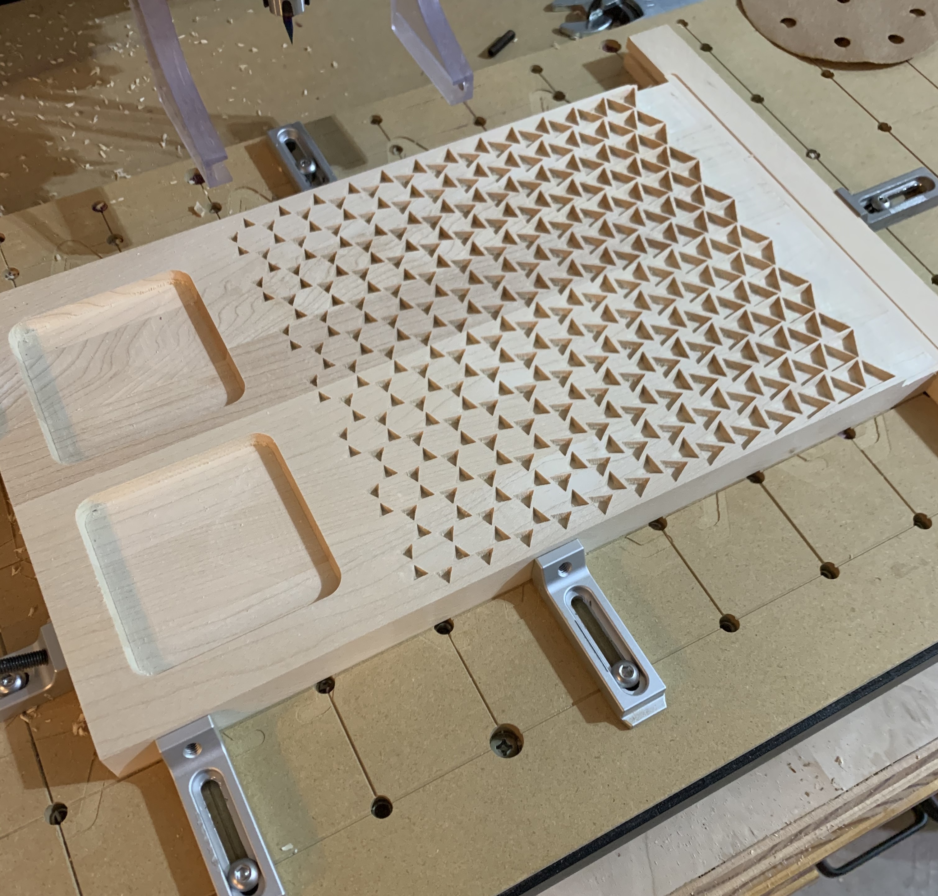
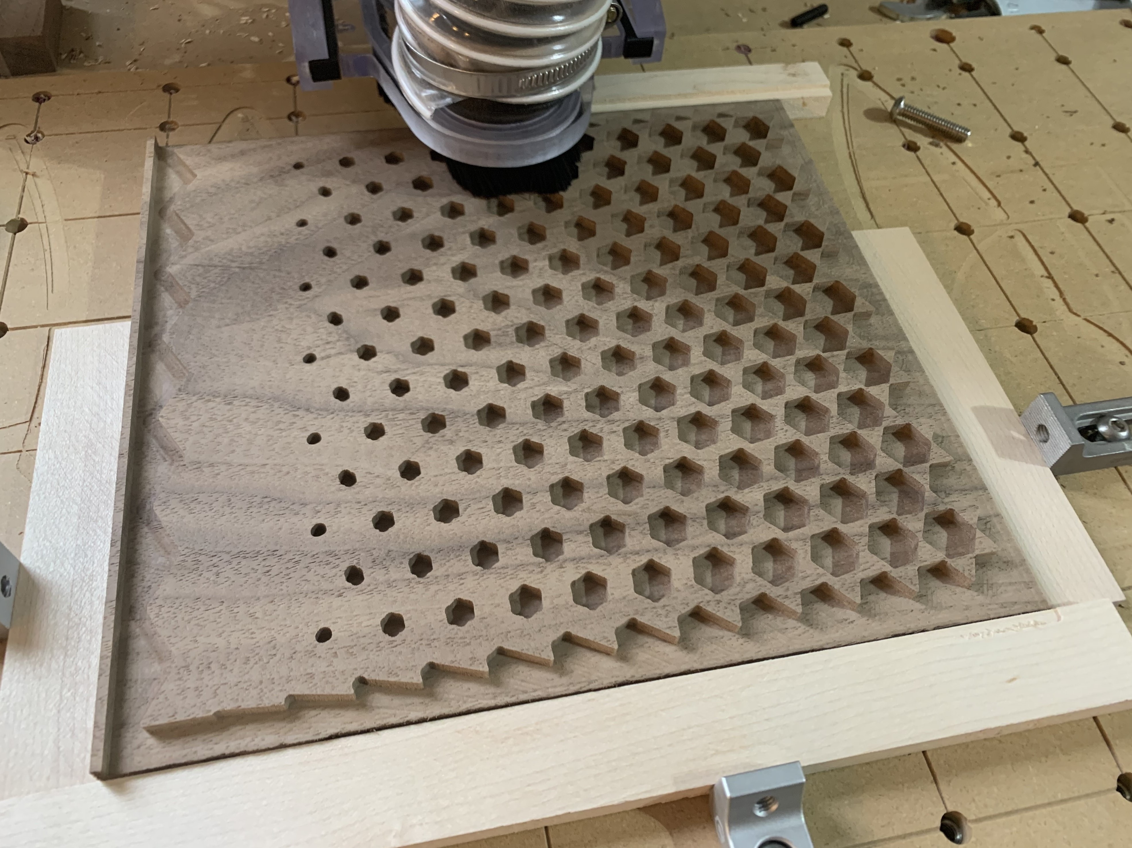
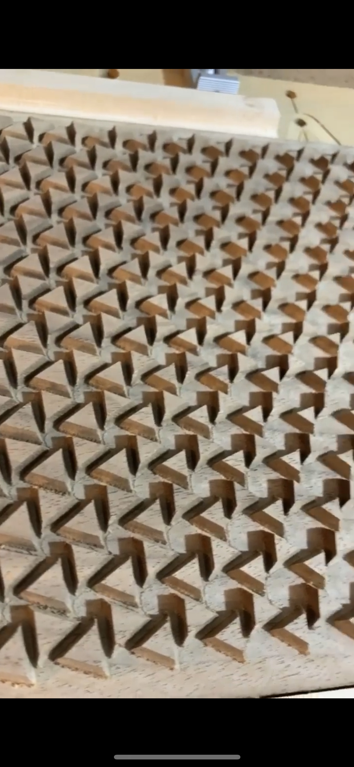
In progress shots:
Toolpaths:
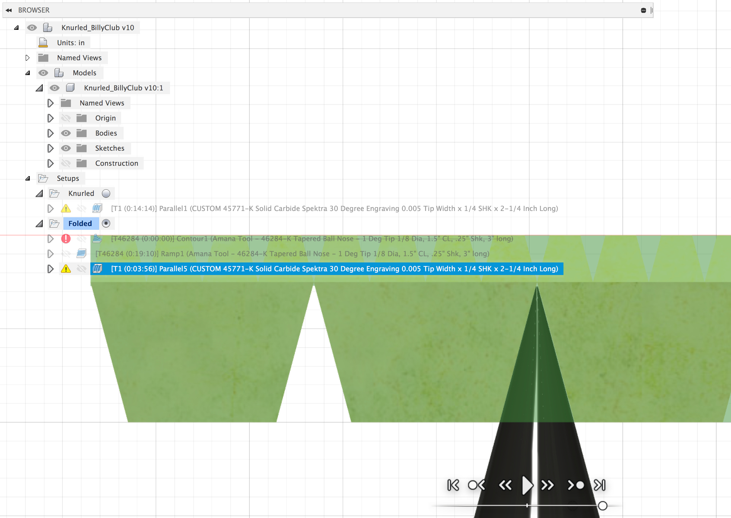
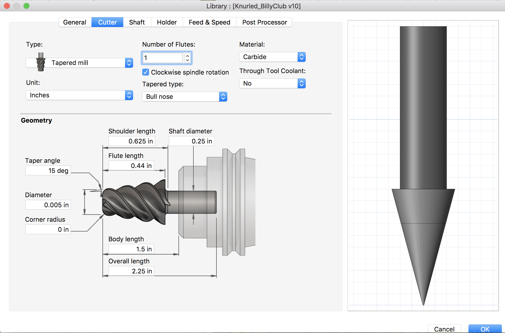
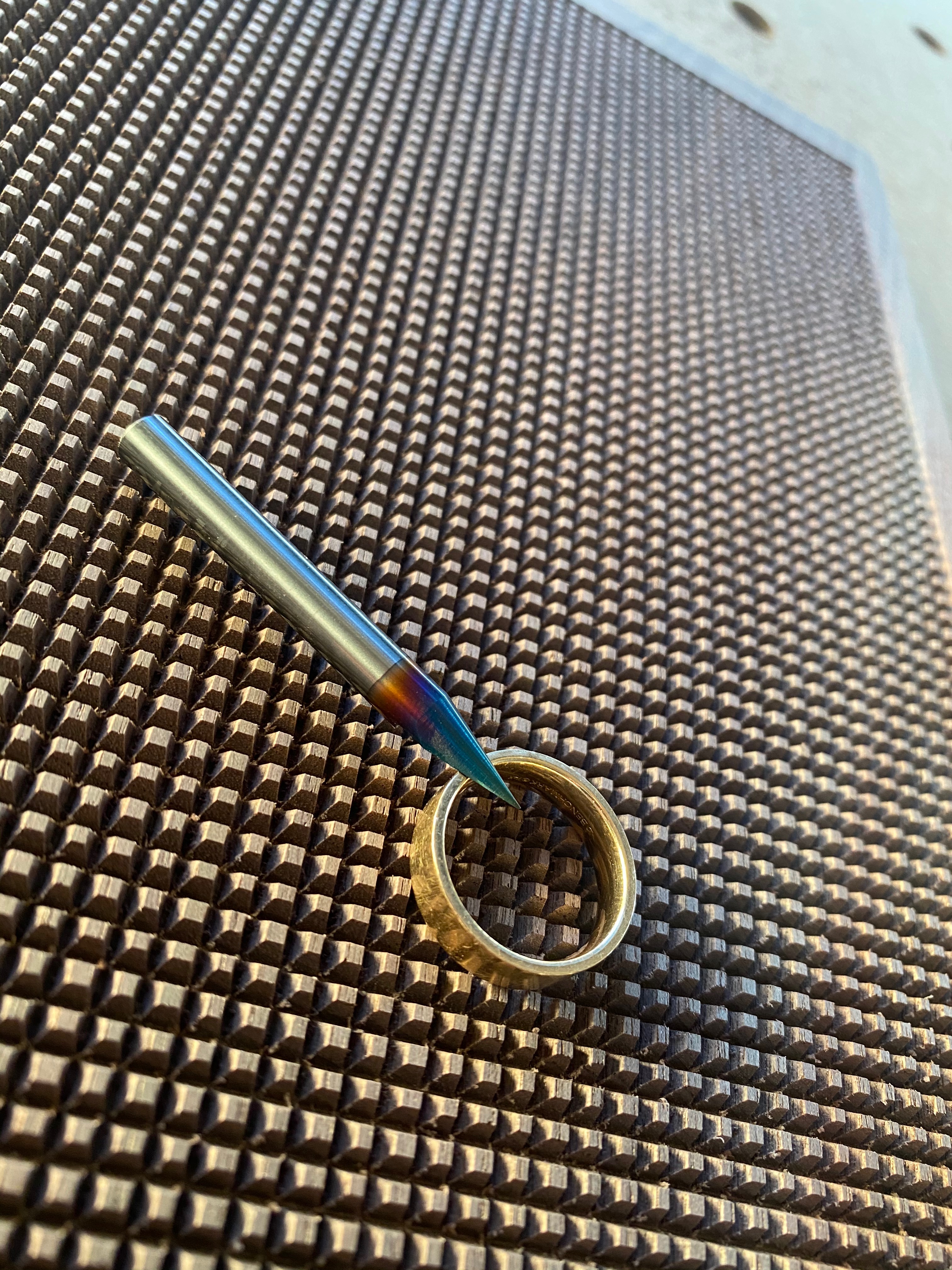
My tool settings here are the default Amana settings for the 45771-K 30Deg V Bit with .44" of Cutting Length: https://amzn.to/2VEcwd3. I’ve just changed it to be a “tapered” mill in F360 because F360 won’t allow 3D toolpaths with Vbits. And because I didn’t entirely trust it I paid special attention in the simulation to make sure that my manually set stepovers followed my design precisely and didn’t do some sort of compounded tolerance smoothing that would throw everything off.
After I had my knurled cylinder … I was like “huh, that was easy; what should I make with this”… Ideas such as a Lamp Body/Shaft, billy club, shin splint/muscle roller, pizza dough aerator, napkin rings, bracelet, etc… point is that it’s taken what would have been extremely laborious and time consuming using a lathe and cut down the production time dramatically and the applications for a production shop are endless (goal #1). I chose planters because who doesn’t like green things and I’m trying to build out designs for an Etsy store to argument my high-end design and furniture business.
The maple base was also cut using a v-bit… but I think we can agree this post is getting a little long.
My Favorite Cut
Because I didn’t decide these would be planters until after gluing up the cylinder, I felt like the inner diameter needed a chamfer down to the “soil-level” to help contain soil and water from rolling over the edge. Problem was finding the perfect center to zero from and holding down the glued up cylinder… enter rubber bands and my custom made cams. There’s something intensely satisfying about watching it snap the rubber bands it used to zero X&Y each time.
Finish:
I drowned these in FOOD SAFE Art Resign epoxy (https://amzn.to/2wt8PMA) and let a bit of epoxy pool on in the bottom of the planter… this should ensure that any water can’t be absorbed into the wood or seep out imperfect joints.
PROTIPS before you try yourself:
- Cut yourself 2-3 Dodecagons (12-sided polygon) to help during glue up. I used CA glue to tack the kit-kat bars and wood glue for the final bond but some Dodecagons would have kept everything from sliding around on me.
- Keep your kitkat bars in the order they were cut and glue immediately after machining, this should help with any warping the wood wants to do after being cut.
- Use a better hold-down method than double sided tape my 2D contour tool path sounded like it was going to vibrate the piece to death on the final cut-out.
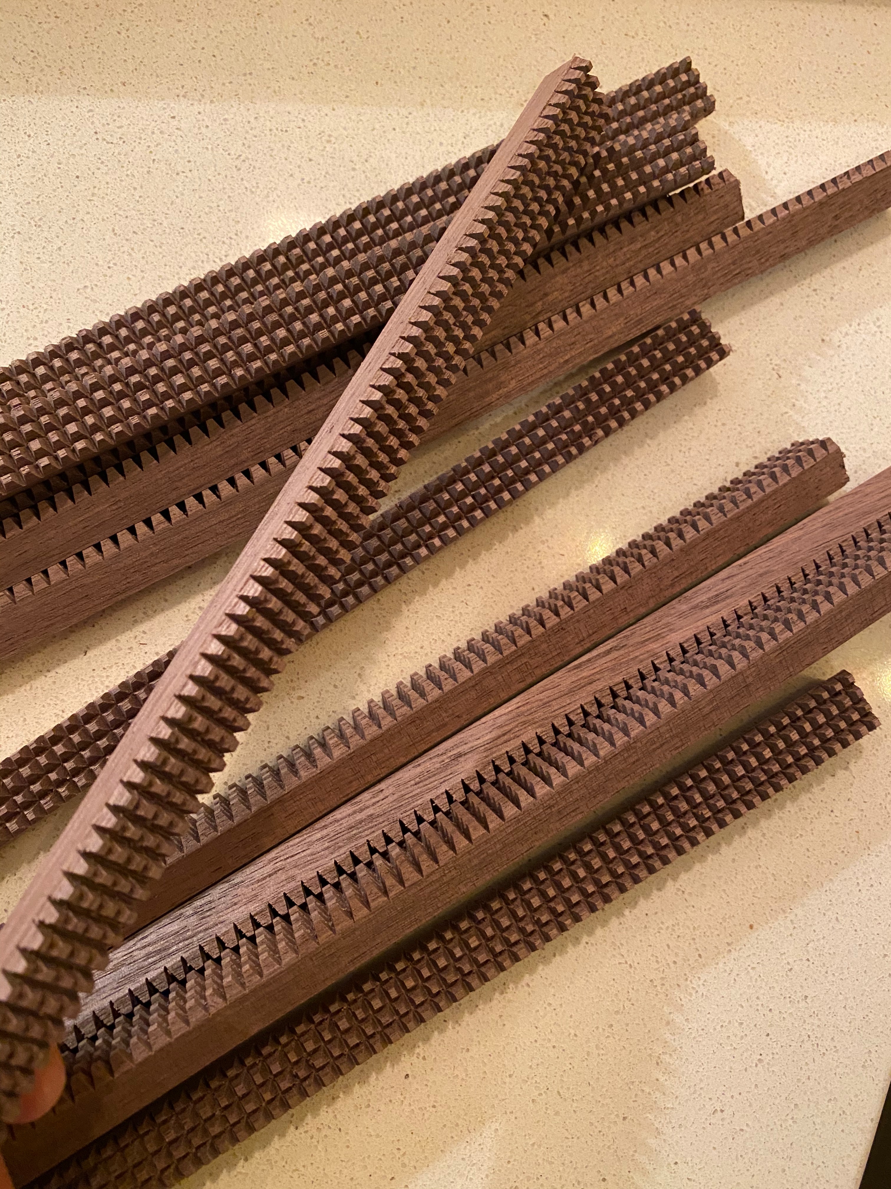
- Use larger “knurls” and machine the long grain first before cross-cutting with the parallel toolpaths, this should help with chipping out the knurls and breaking the pattern.
Fusion File:
https://a360.co/2VGLTnL
19 Likes
 ⠀⠀⠀⠀⠀⠀
2 Likes
Not to derail the topic…
As a guy who makes part of his living every year off of flags and signs, I am curious as to why you would “loathe” even the idea of such a project…
edit: i should go ahead and say there was no offense taken to your comment, just genuinely curious
Sorry I didn’t mean to offend, I’ll take it to a PM and explain.
No worries, you have inspired me to look into fusion360 as I would like to start applying my sign/artwork skills towards more creative endeavors! Again, absolutely stunning work!
3 Likes
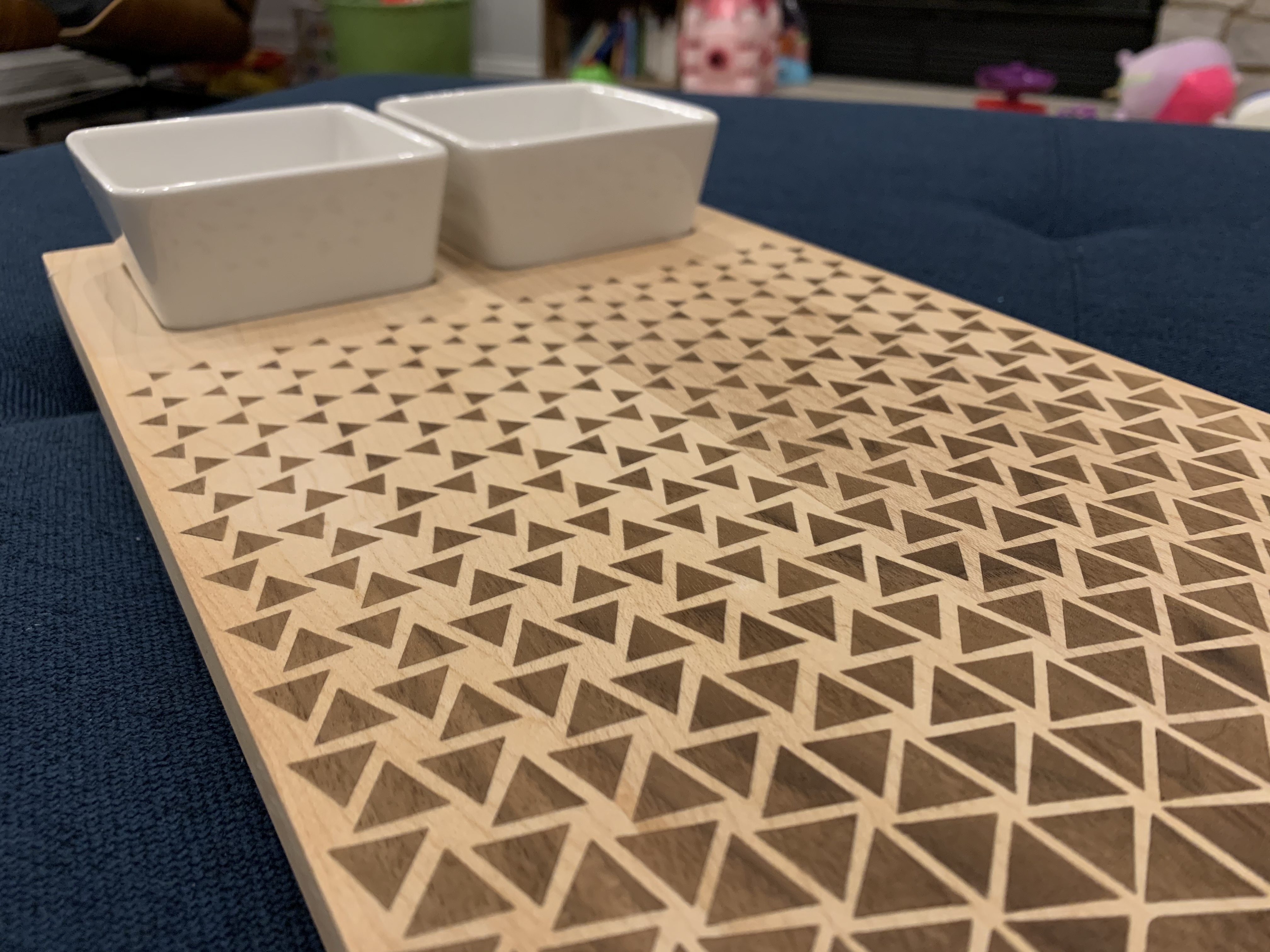
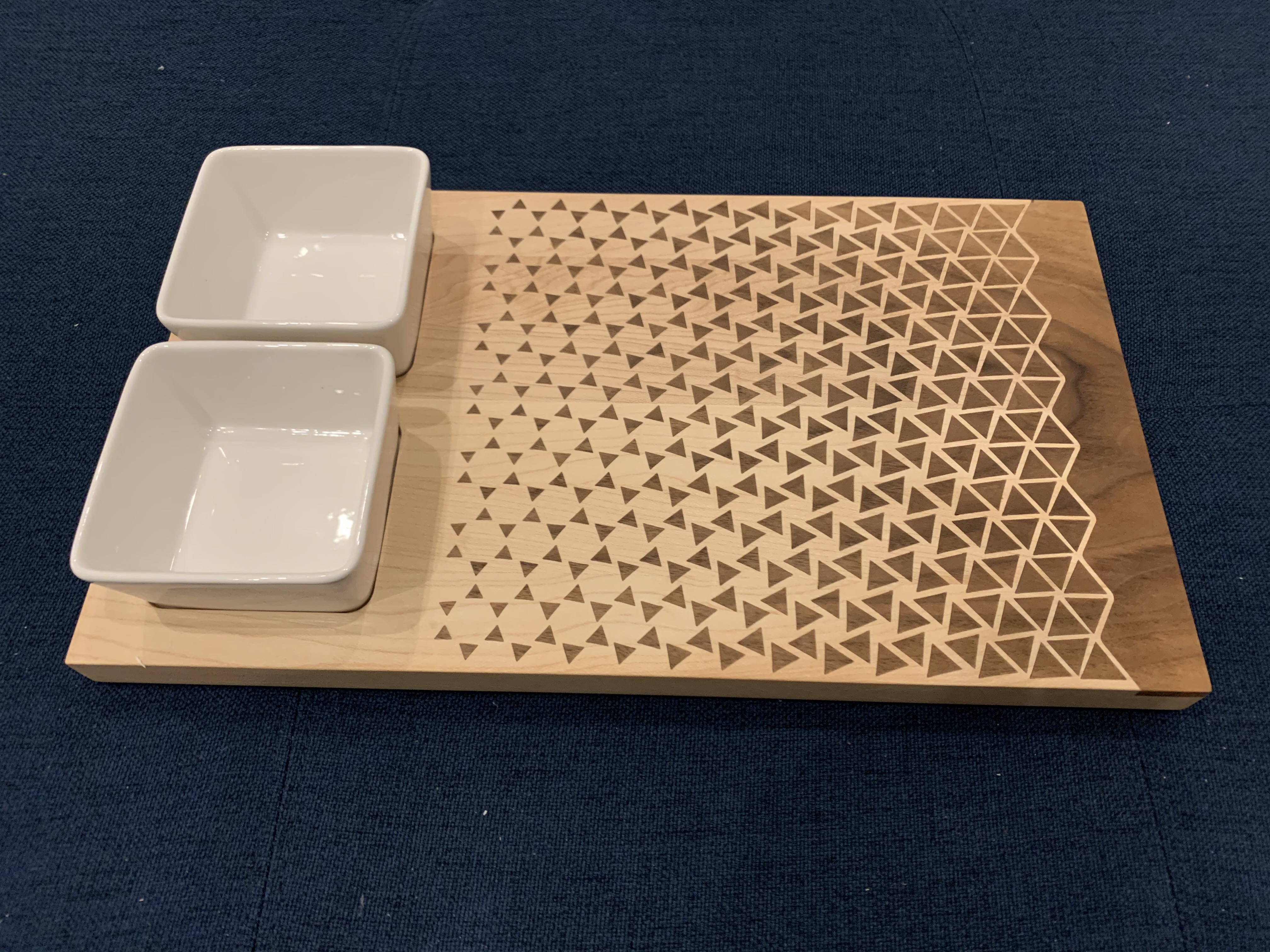
I would like to submit this serving tray that I made for your consideration. It is a walnut V-Carve inlay on a Maple base. I had previously done some basic V-Carve inlays and decided it was time to try something a bit more complex.
The first step was carving the base. I used Vectric’s VCarve Desktop for CAD/CAM following the commonly mentioned tutorial (https://youtu.be/l4VMo9DCzO8) for setting the depths and start heights. I did a clearance pass with a 1/8in endmill then a finishing pass with a 30deg V bit. I was super conservative with the speeds and feeds so this carve took about 4-5 hours. This was also the first project using the amazing gator clamps and they worked like a champ
Next was the inlay. With my first attempt, I learned a hard lesson that when you set a start depth in VCarve it assumes there is no stock there, adds on the depth of cut and plows. This was too deep of a pass and was chipping out all the triangles. To rectify this, I took a flattening bit and erased my mistakes and started fresh. This time I set my Z at a very calculated distance above my stock so that first pass would not be as deep. Again I ran very conservative speeds and feeds because those triangles were just begging to chip out. This took somewhere around 6-7 hours.
Clarence pass:
Final Pass:
It was super satisfying testing fitting them as they fit perfectly together:
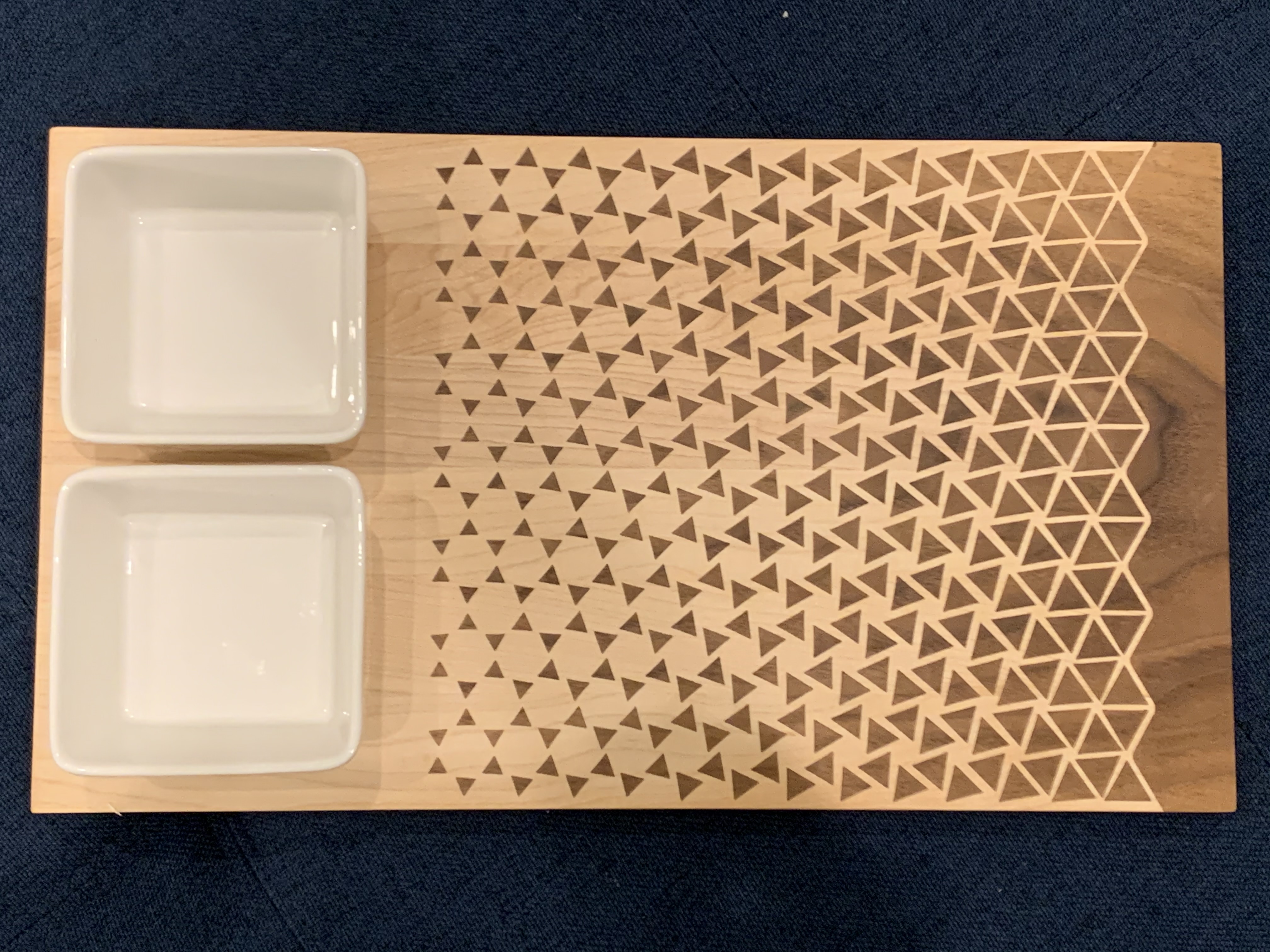
After some glue and every clamp I could find, I let the glue dry then took it back to the Shapeoko with a flatting bit to remove all the excess from the inlay. I love how the walnut shows continuous grain throughout the inlay. As a bonus V-Carve feature, the pockets on the end were designed to fit 2 square ramekins perfectly. I put a light chamfer on the bottom but just eased the edges on the top.
I decided to finish the board with Walrus Oil (Oil and Wax) since it will come in contact with food.
Finished glam shots:
Vector and Vectric Files:
24 Likes
Awesome work, thanks for your entry.
Are you willing to share the design file ?
1 Like
I’ve added to my post a link that contains the original raster image, vectorized image, and the two VCarve project files.
5 Likes
That is gorgeous!!! That is one neat pattern.
2 Likes
I do wish that everyone’s submissions were uploaded to this forum/thread, because these linked files will undoubtedly disappear one day sooner than the forum files.
Brad, you found my scaredycat point with all those triangles just waiting for the last one cut to pop off and you had to start all over! 
1 Like
I tried to add it to the post, but the vectric files are not allowed as an attachment file type.
I had the same fears @CrookedWoodTex which is why I took a very shallow depth of cut and conservative speeds and feeds.
1 Like
You should be able to zip and add them.
1 Like