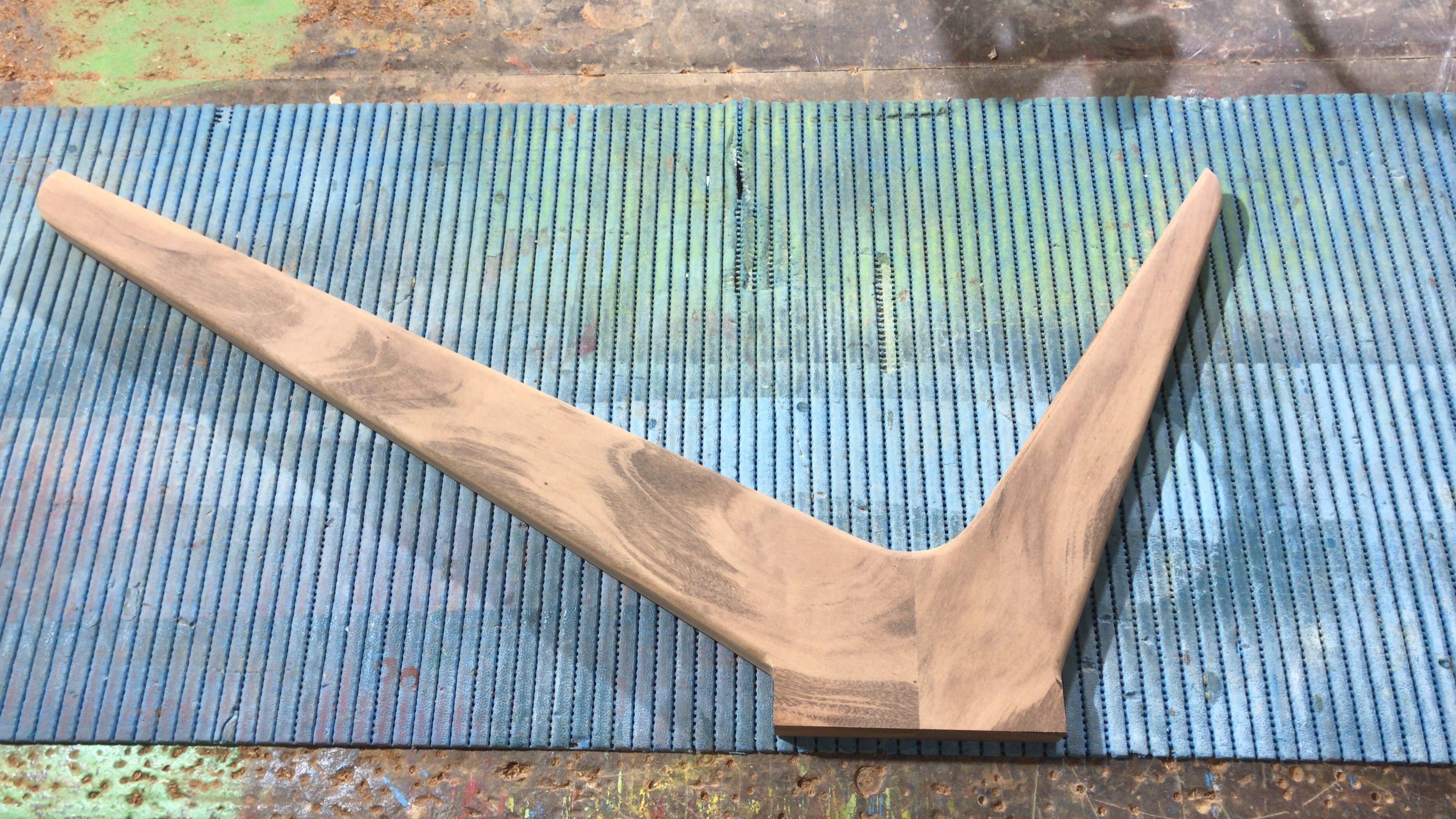
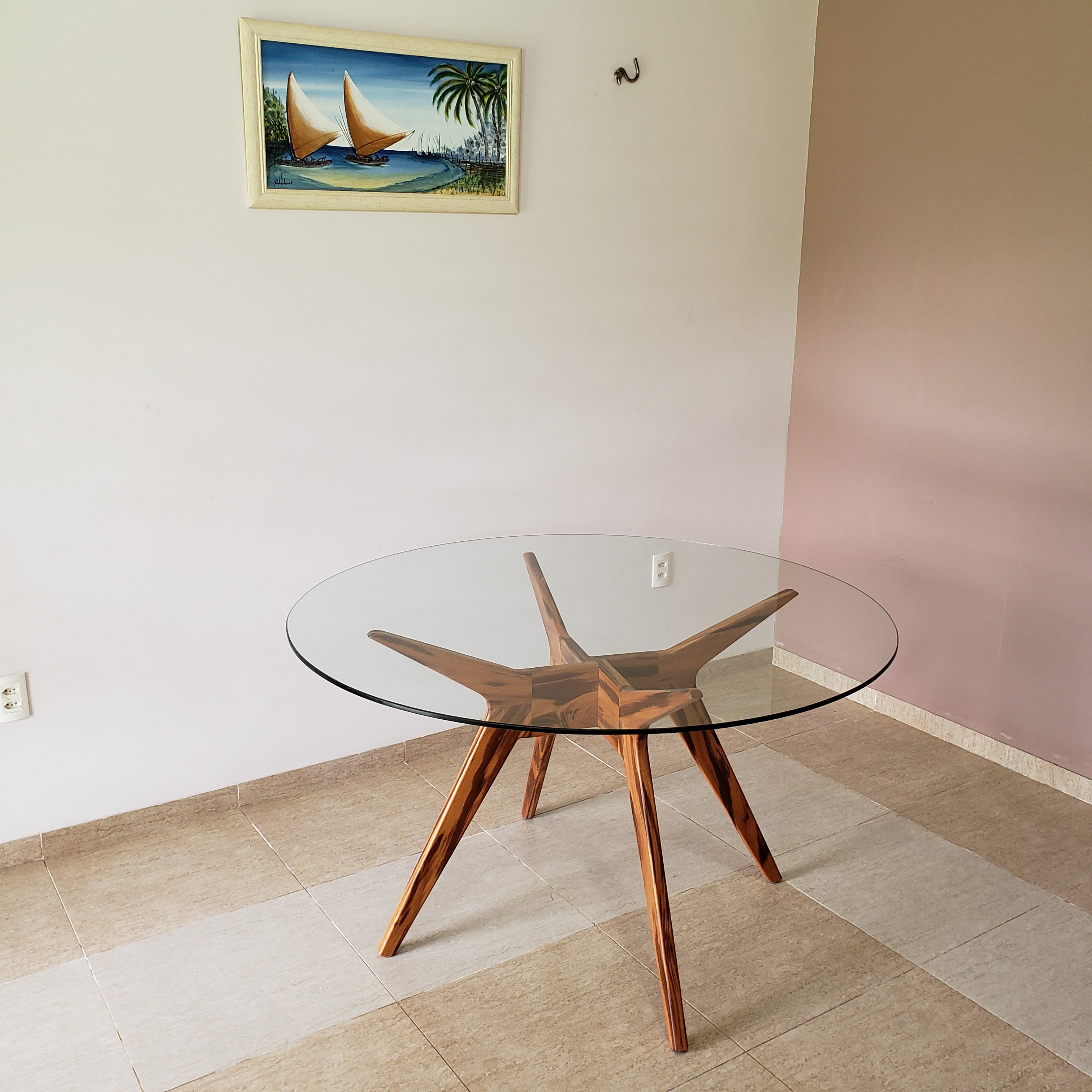
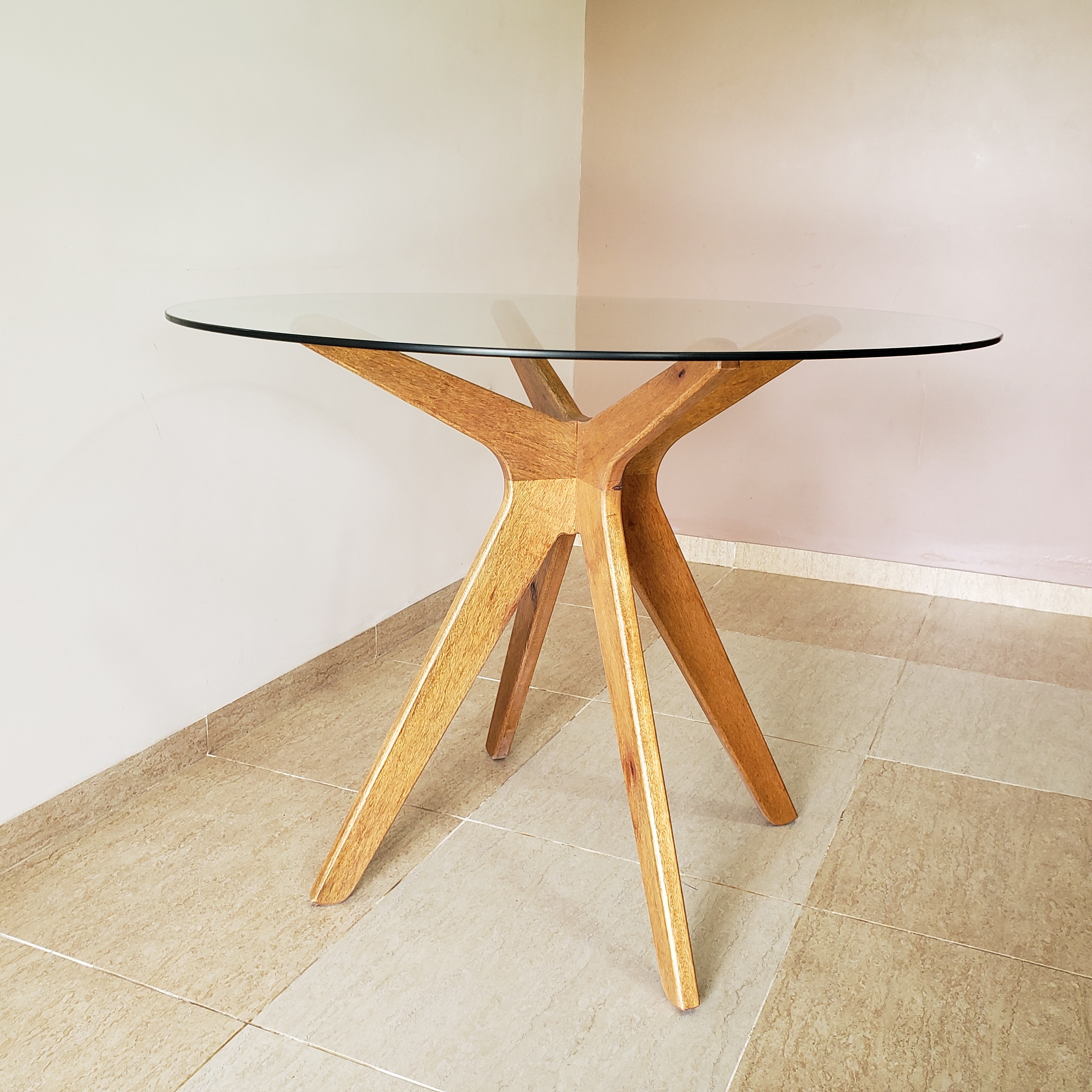
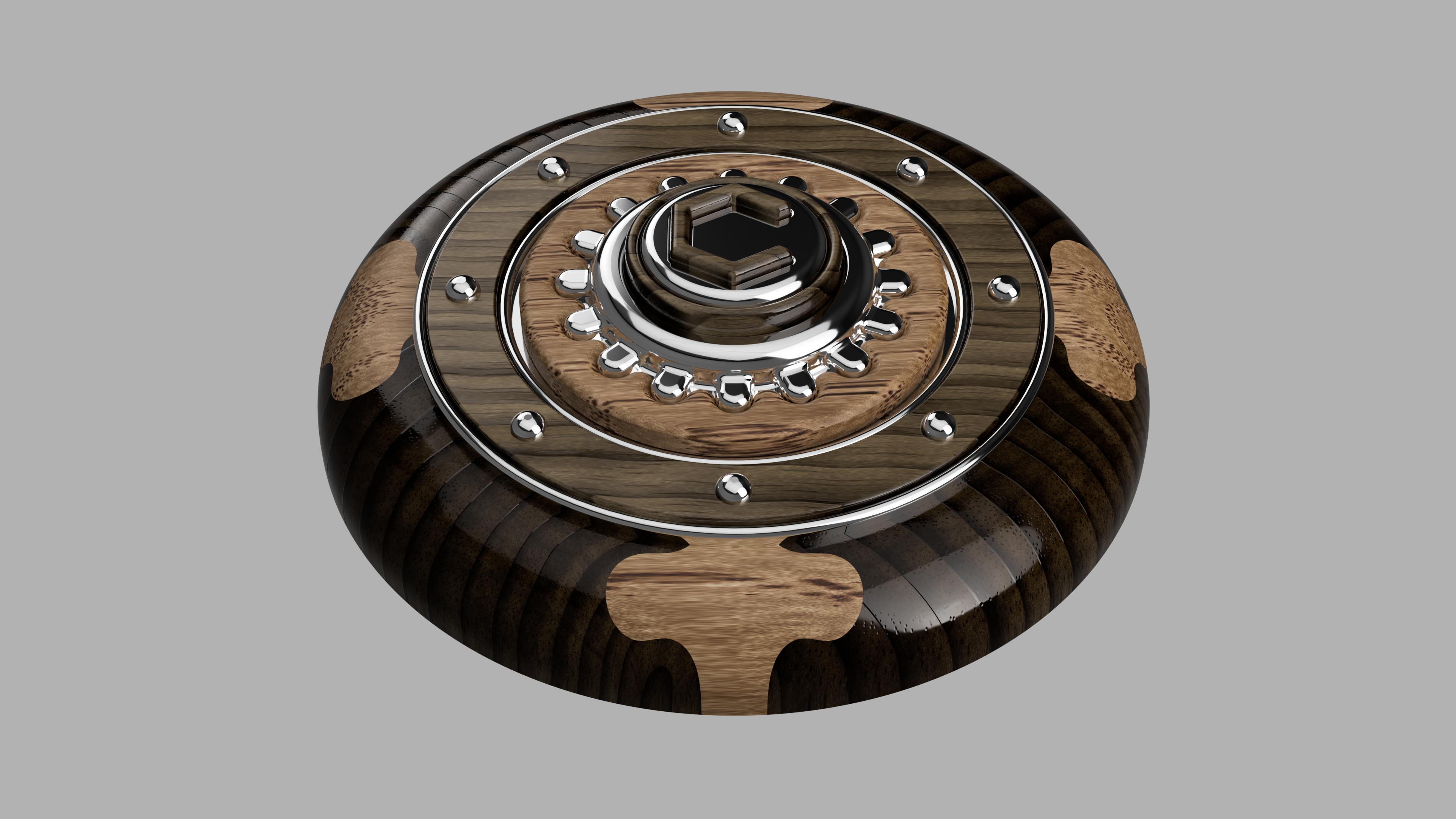
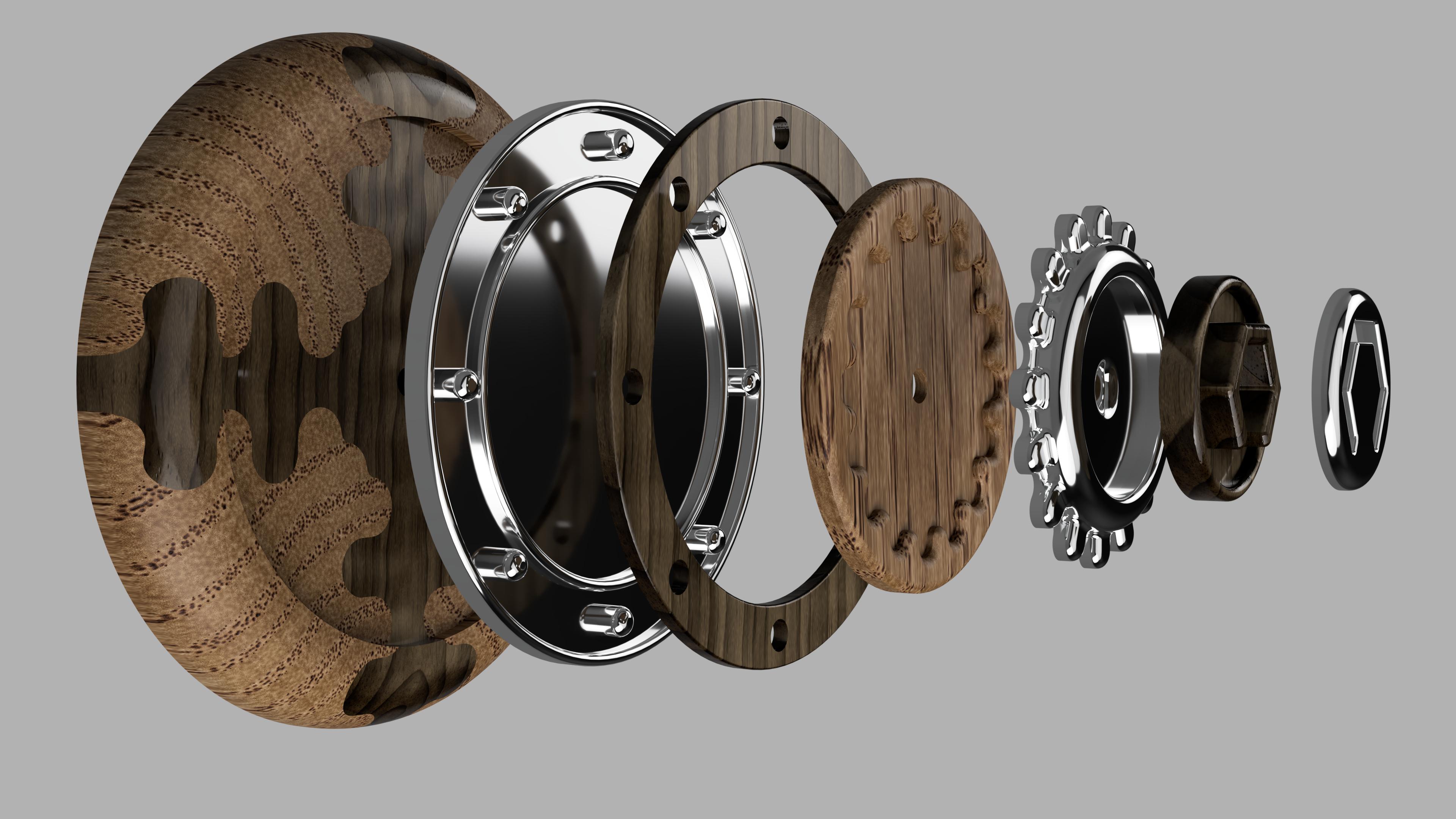
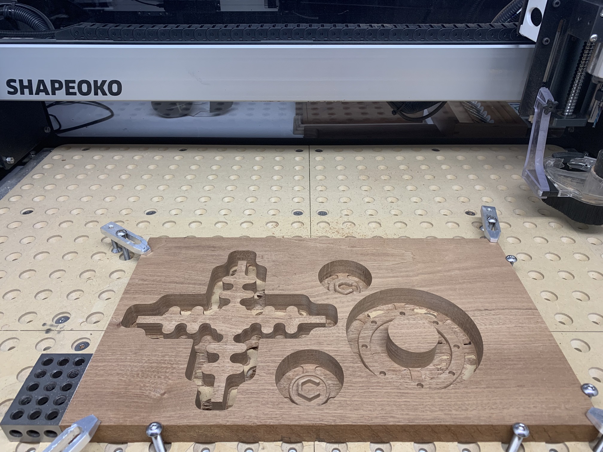
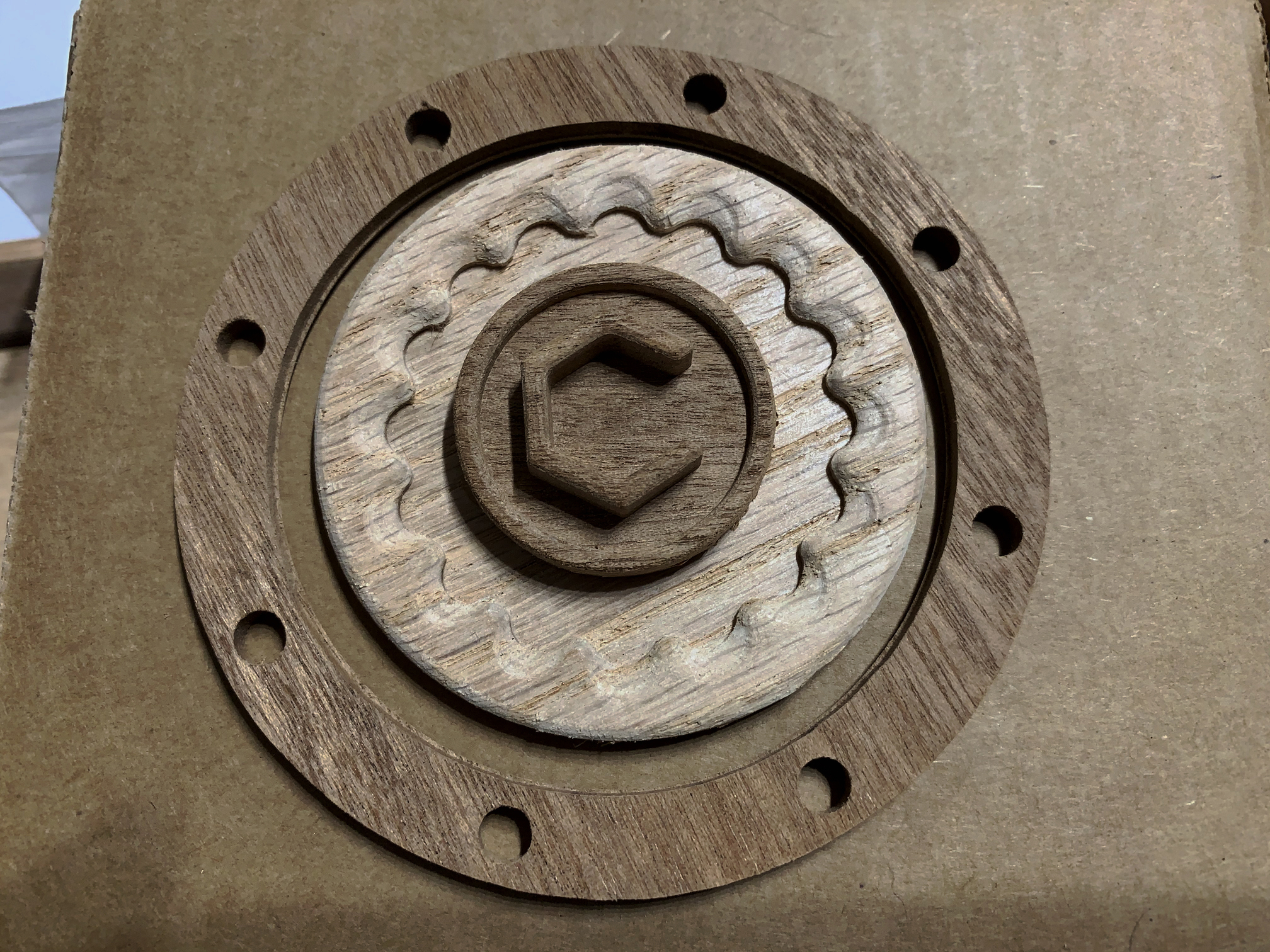
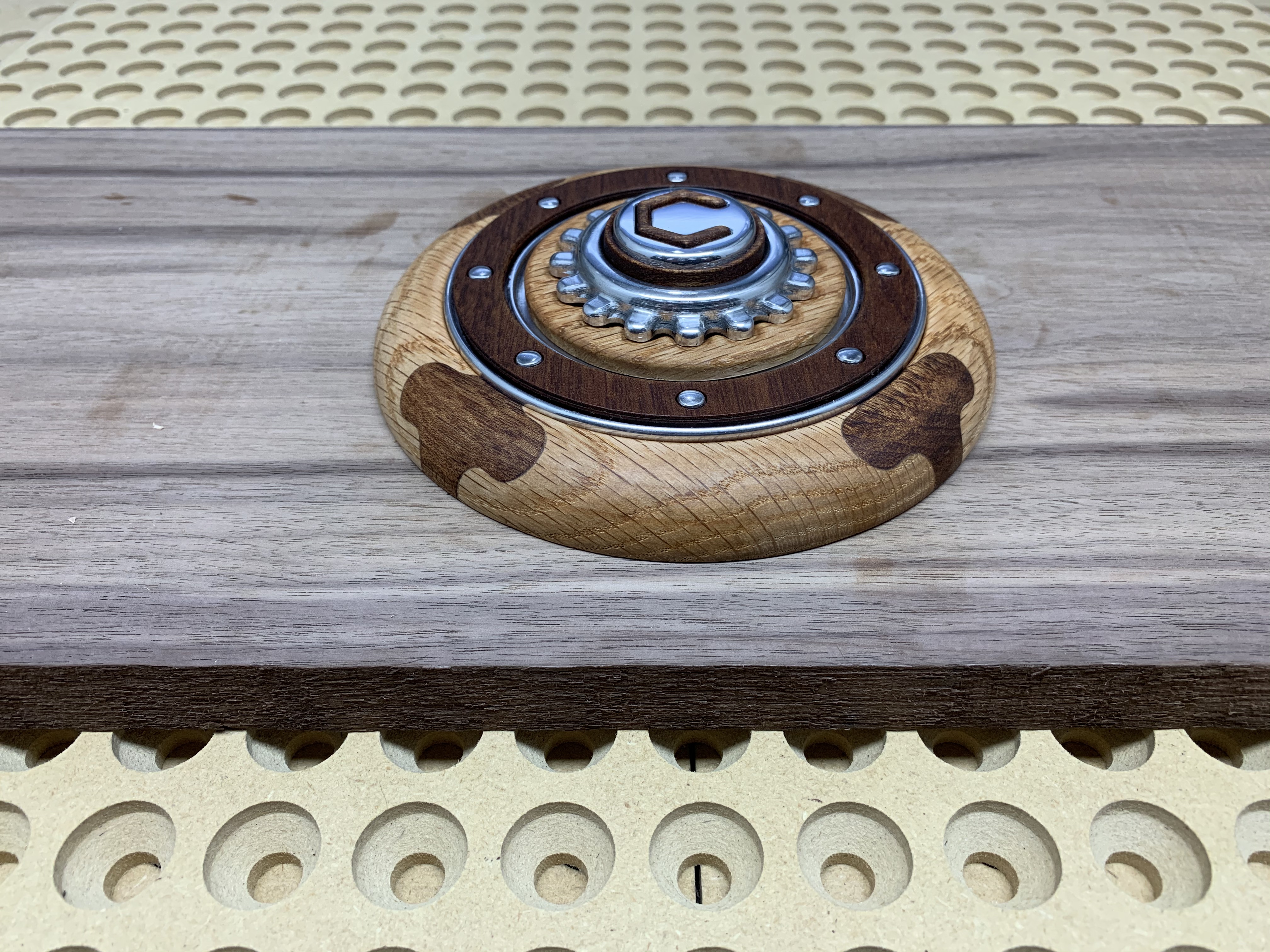
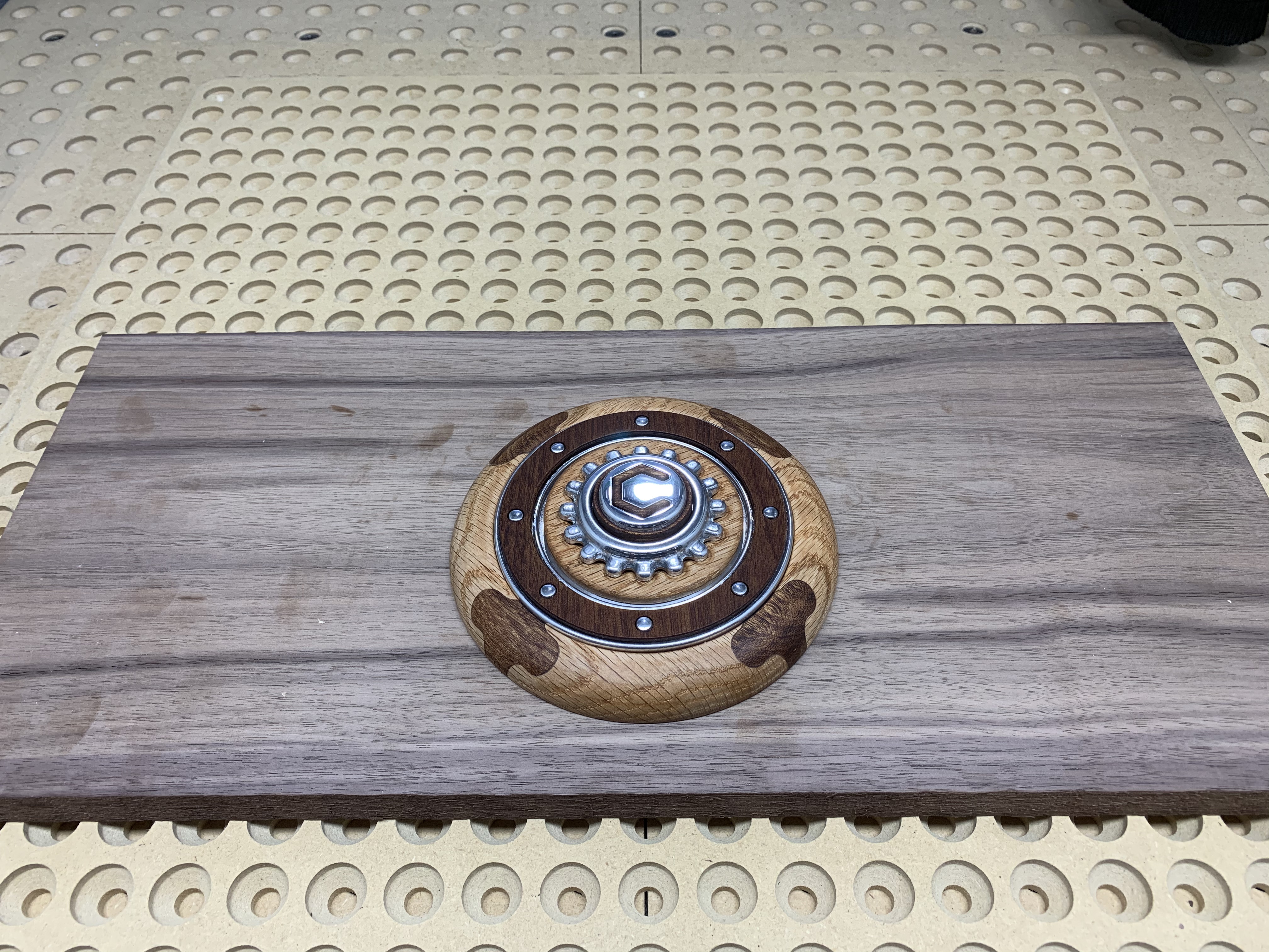
This project is actually the base for a iPad or tablet holder. However, having run out of material, time and design ideas for the addition bearings to the actual holder, I’ll have to call it good at this point. Hoping that @CNCInspiration will have bearing setup suggestions to share 
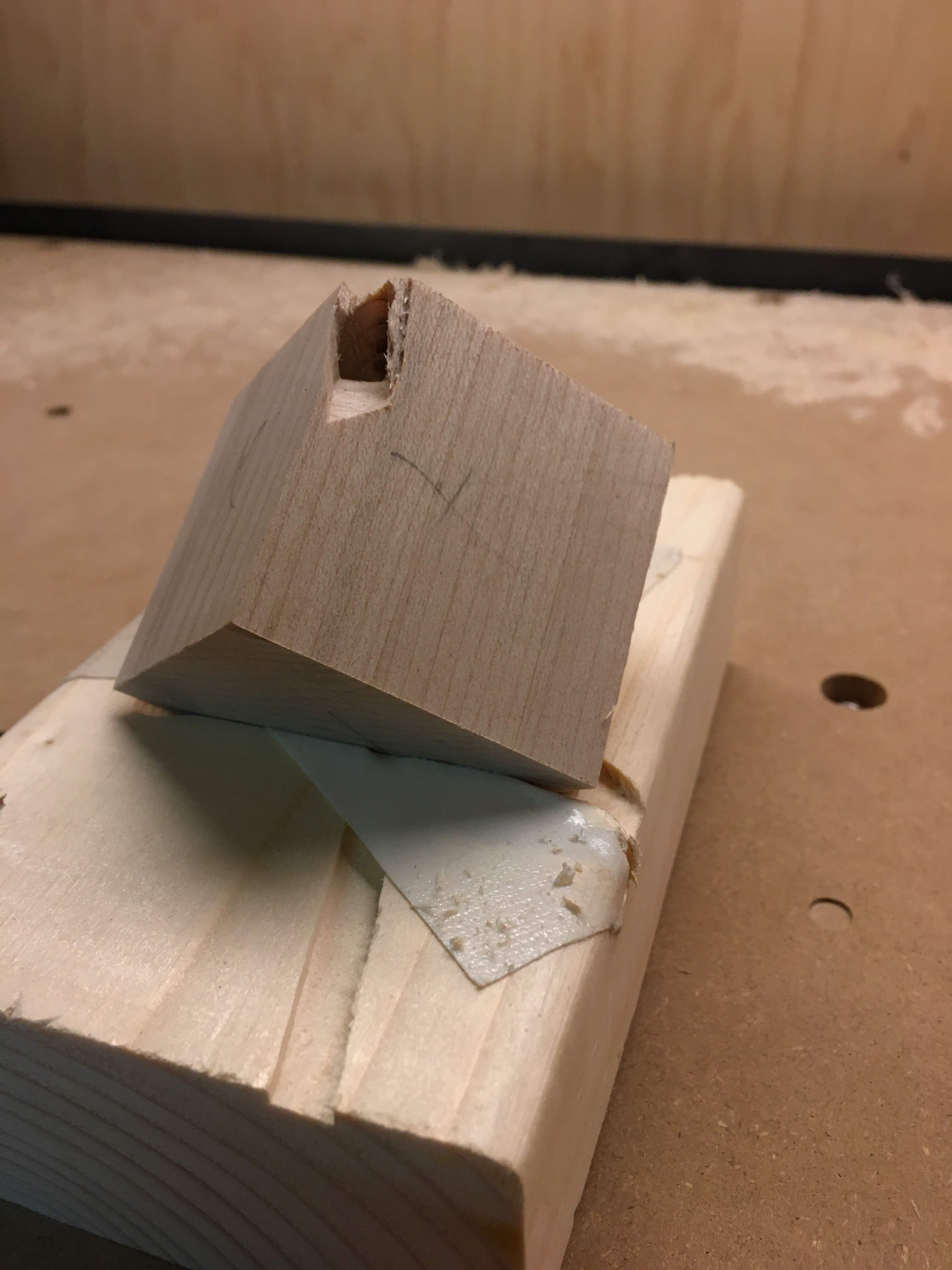
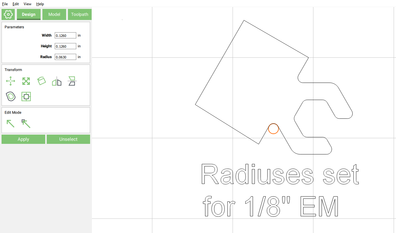
Intending to use a .125 end mill allowing cutting through .750 material all of the joint corners needed to have their radius’s set to allow machining and final fitment without gaps. Creating a circle at .126 and doing a lot of boolean operations to smooth worked like a charm.
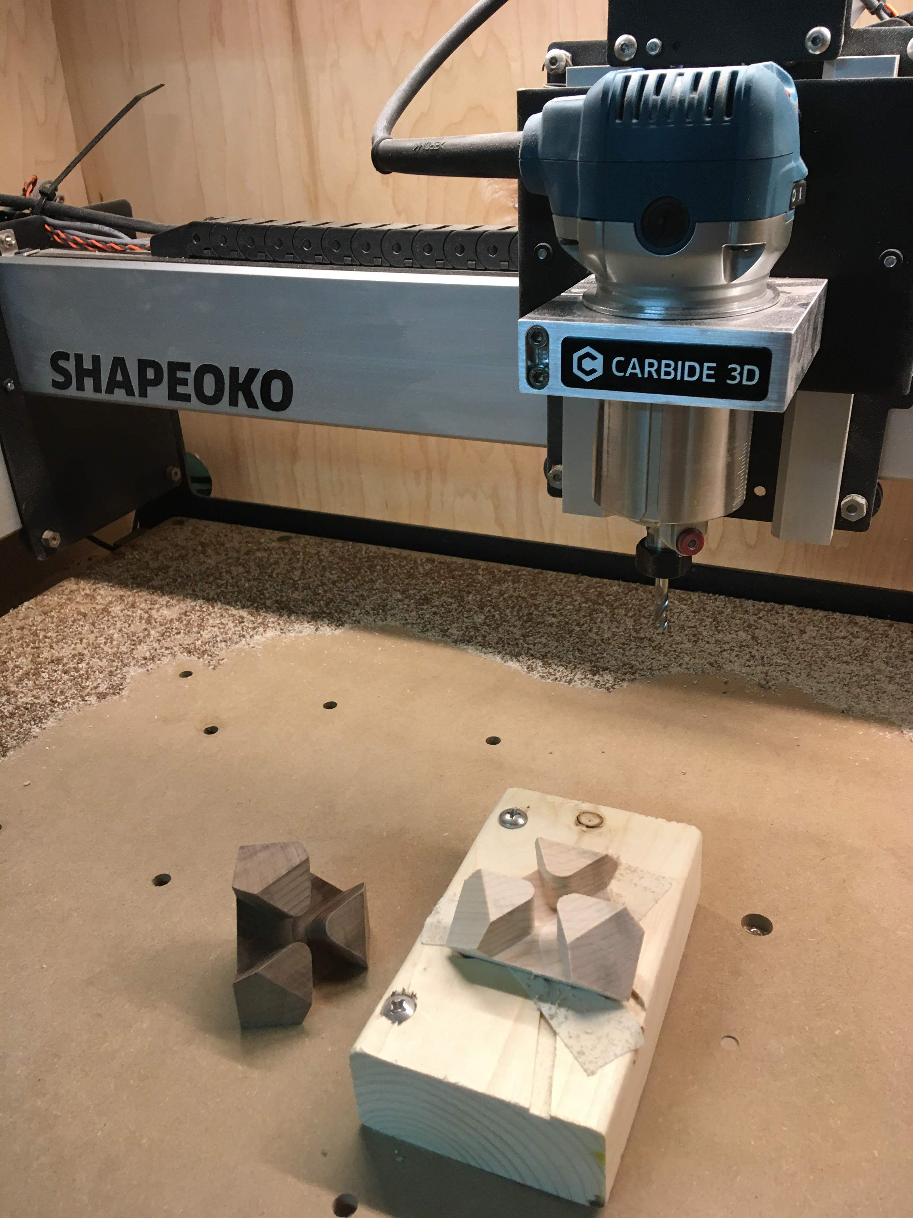
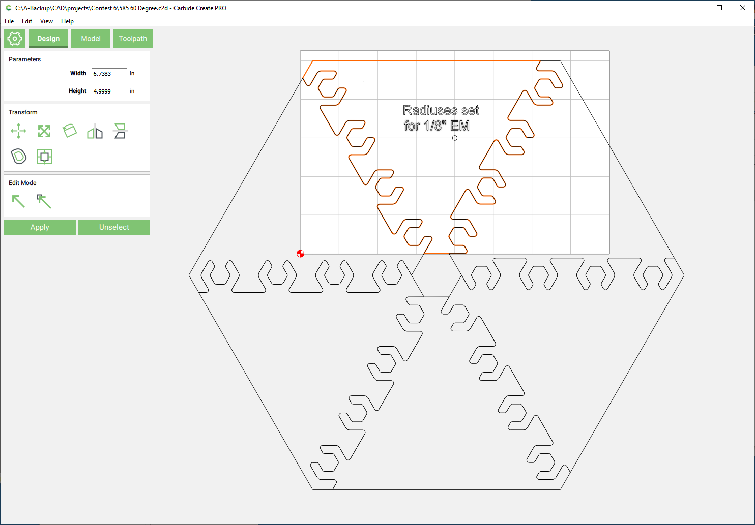
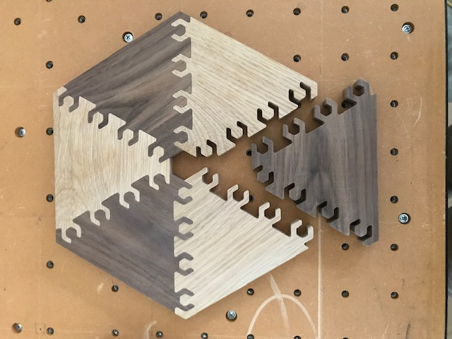
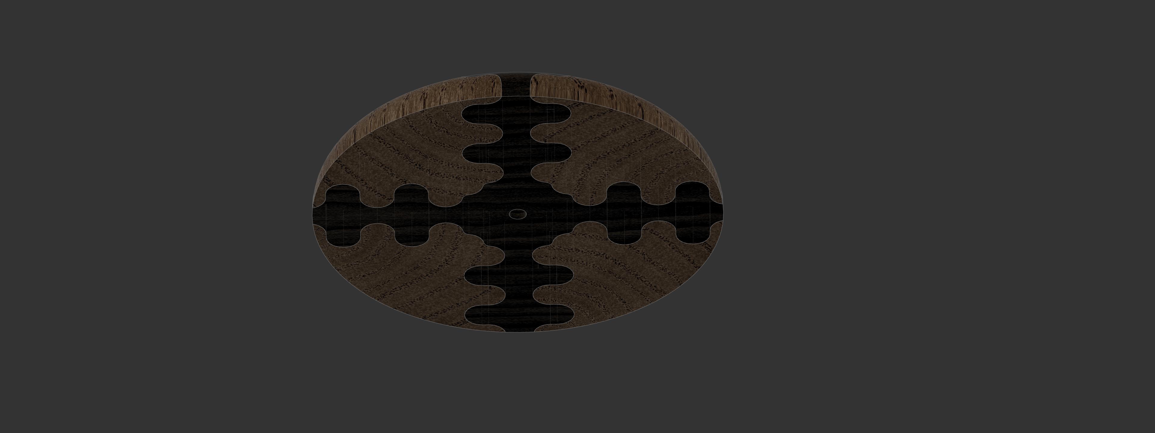
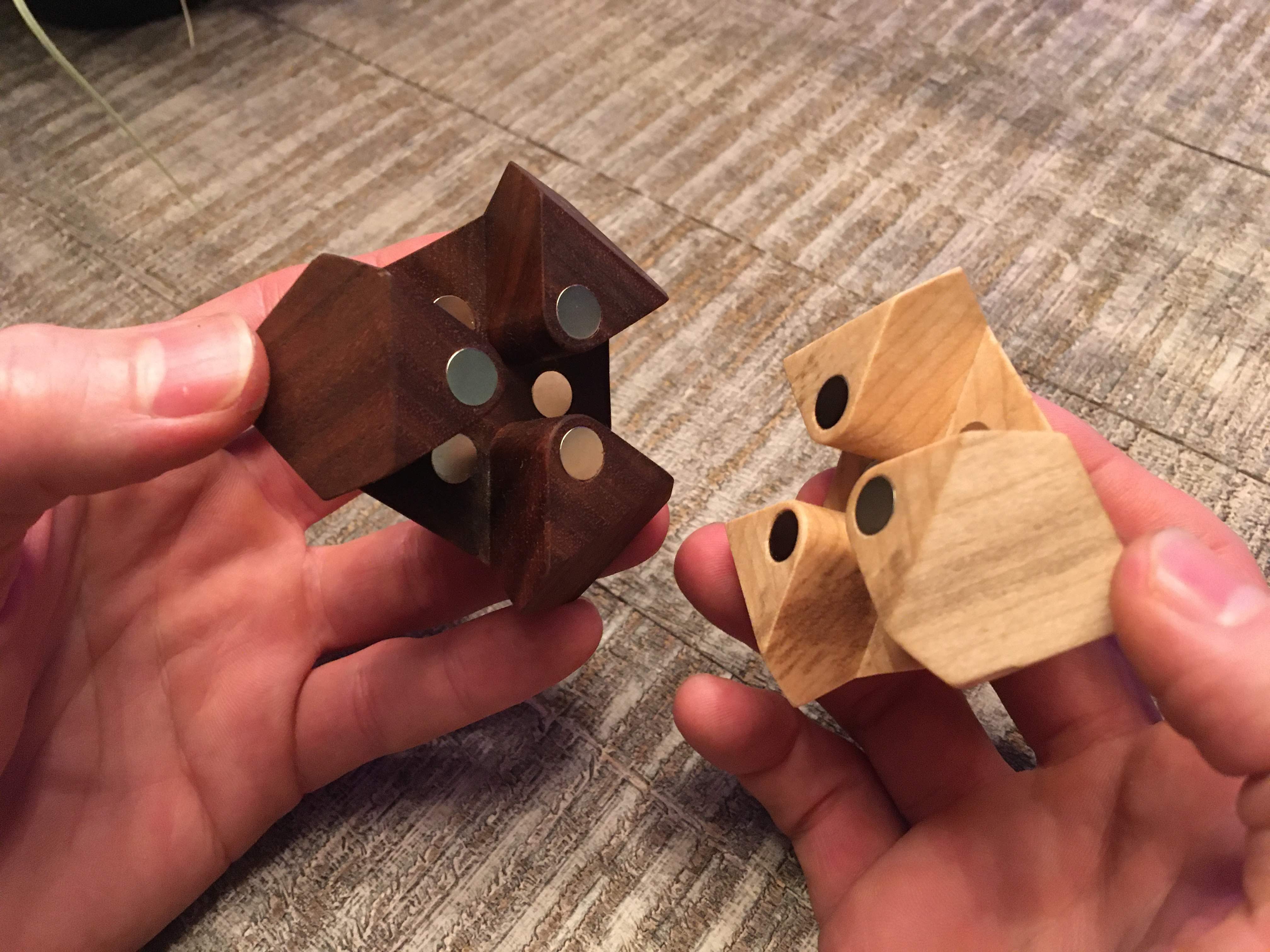
After spacing the joint components, they where joined using boolean operations to create the desired right side joint half. This was then copied and rotated 60 degrees opposite the first joint. To allow the finished pieces to join and allowing for glue, I then did an offset path of .002 to shrink the second half. Both halves were then boolean joined into a single 60 degree segment.
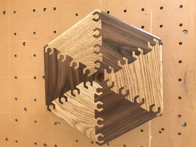
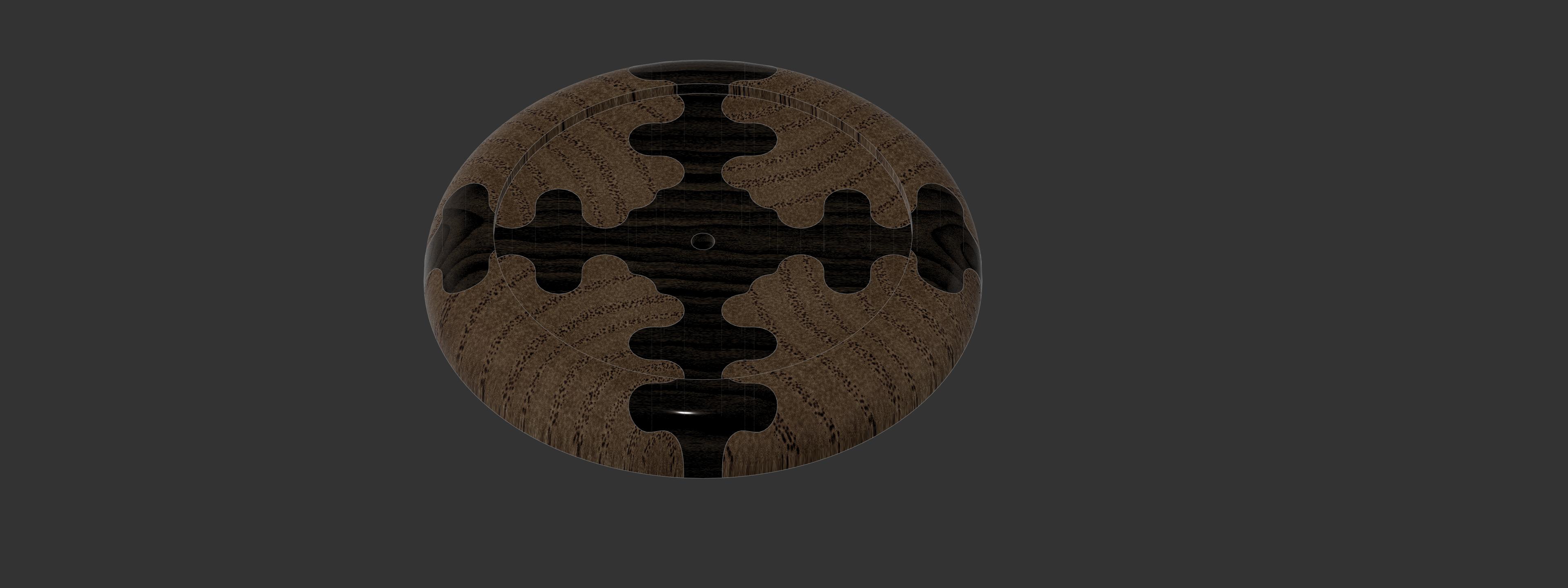
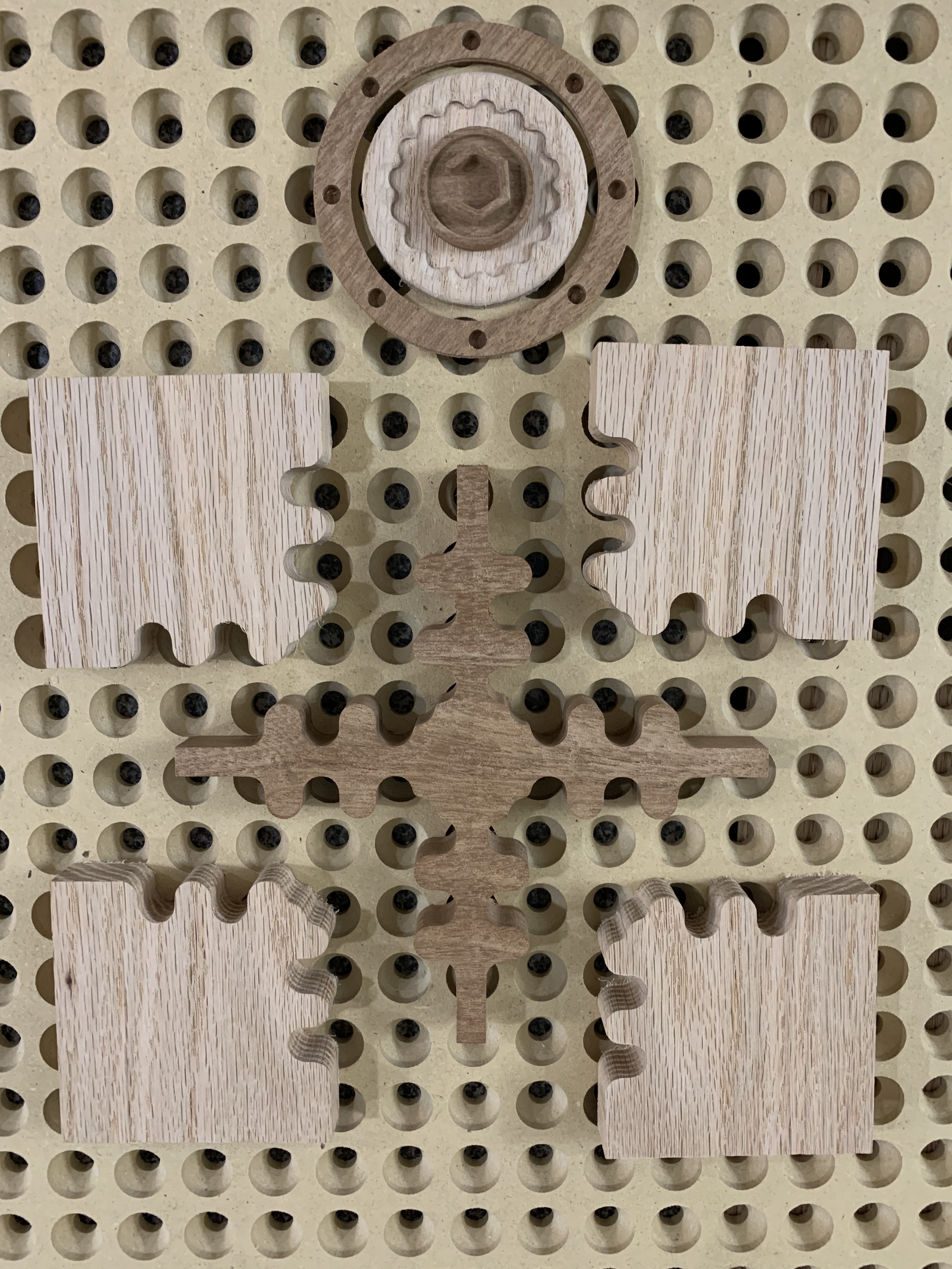
To check design fitment, I created five copies rotating each an additional 60 degrees and joined each at a common mid point.
I used to the default feeds and speeds for a .125 end mill in hardwood. Once cutting was underway I was able to comfortably raise this to 140% in Carbide Motion.
A measuring tool that not only does X, Y but also diagonal would be very helpful…please! Spacing the joint objects required a lot if creating blocks, rotating, resizing and repeating. I suppose a straight joint would be much simpler to achieve good spacing. Or being better at math than having been gifted with.
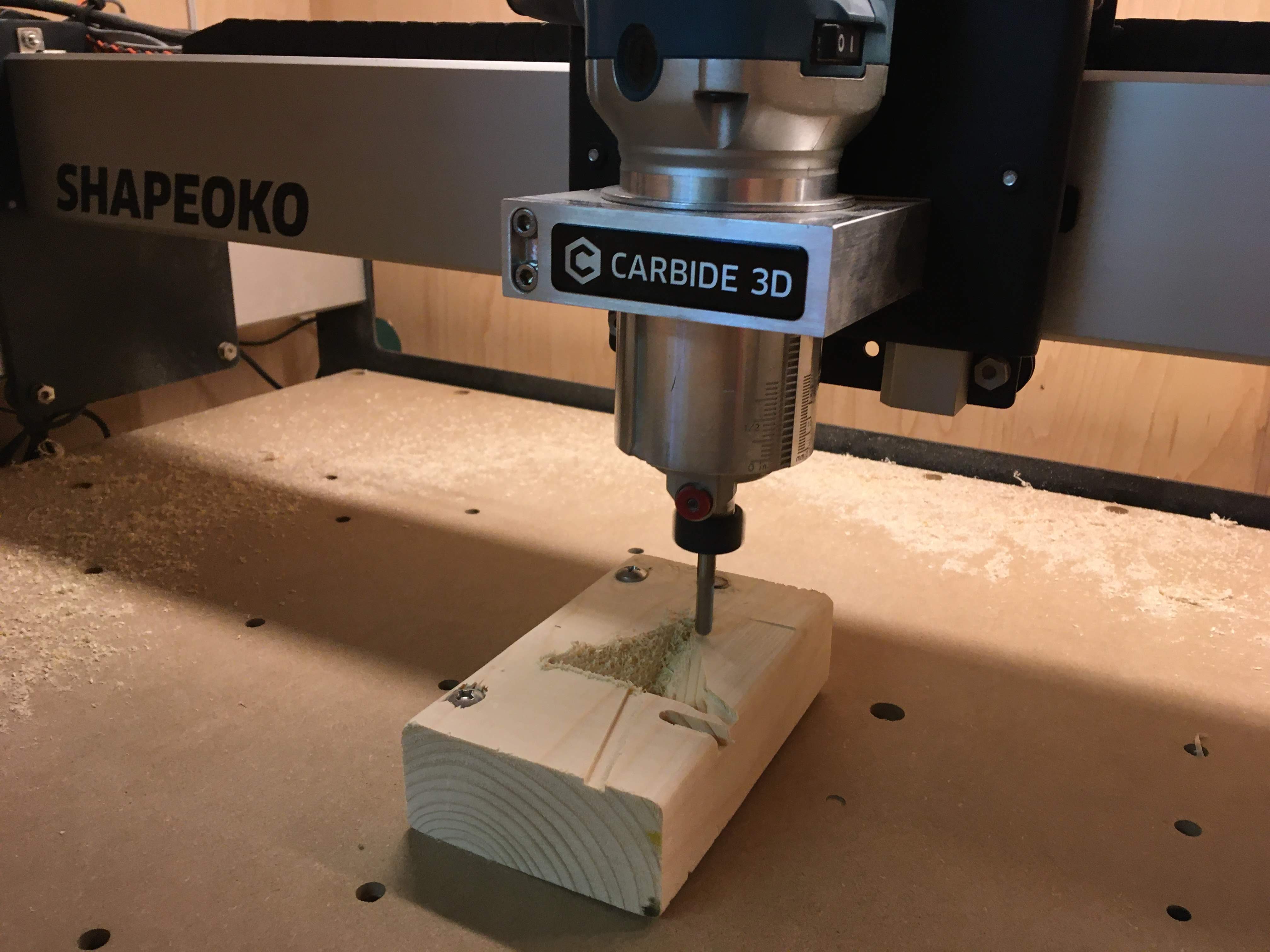
If you decide to use this tool path, use caution as there are no tabs. Instead I left an onion skin of .001-.002 by setting the Z to the machine bed then raising and resetting Z to the material thickness. Removing the skin only took a few strokes with 220 sandpaper.
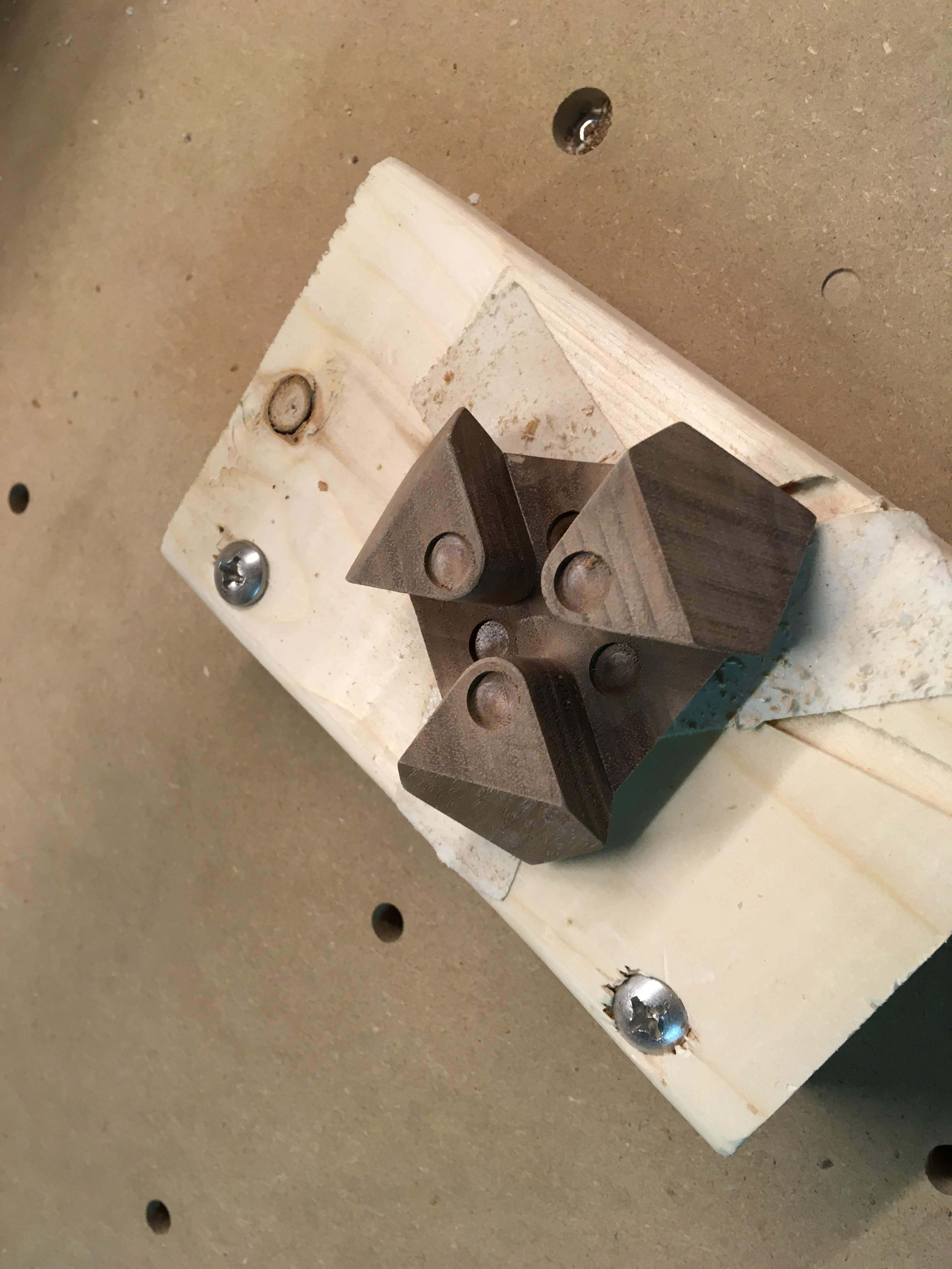
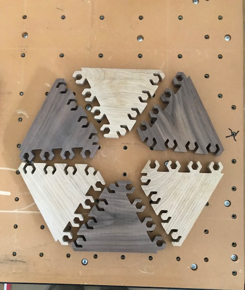
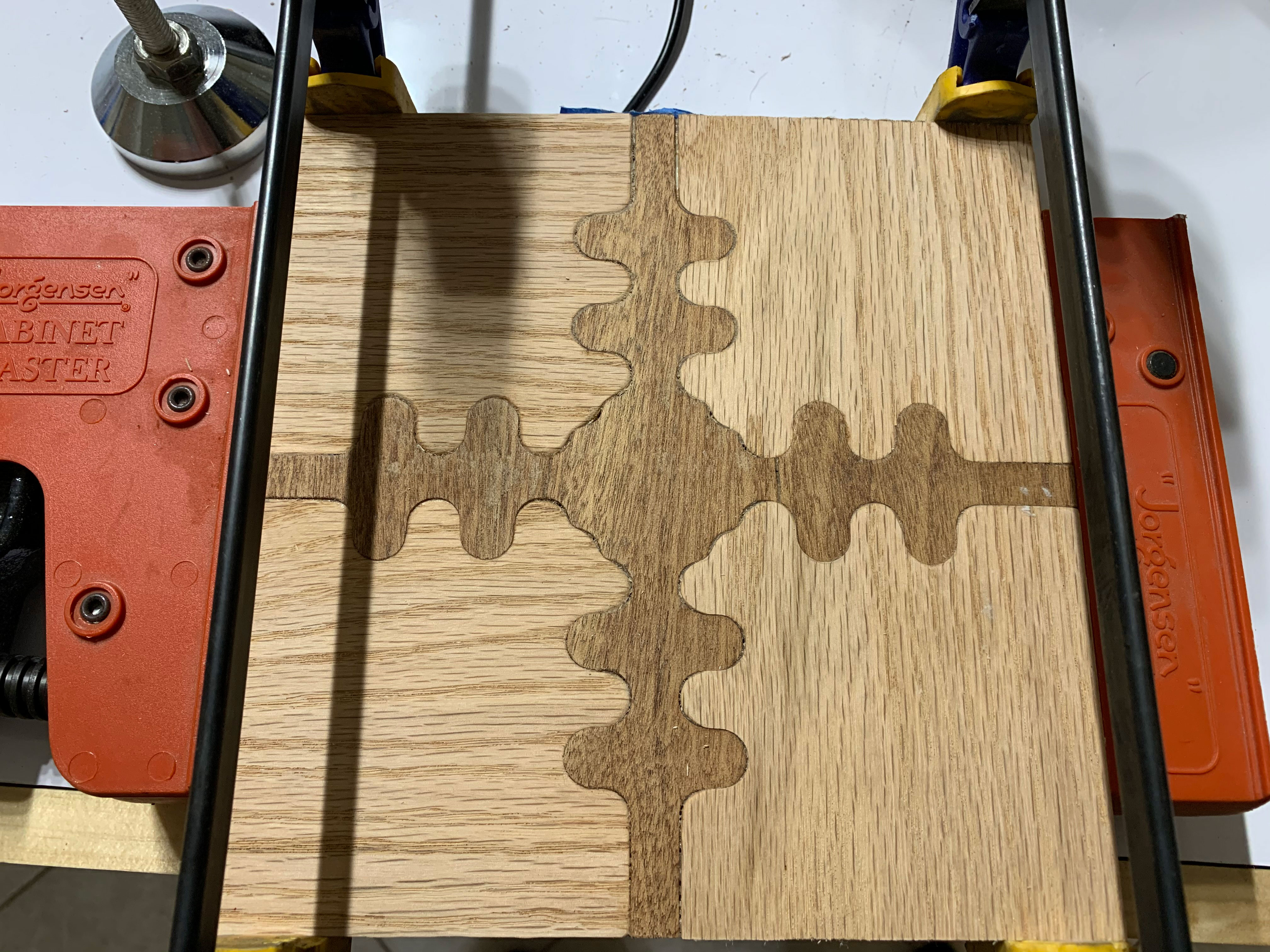
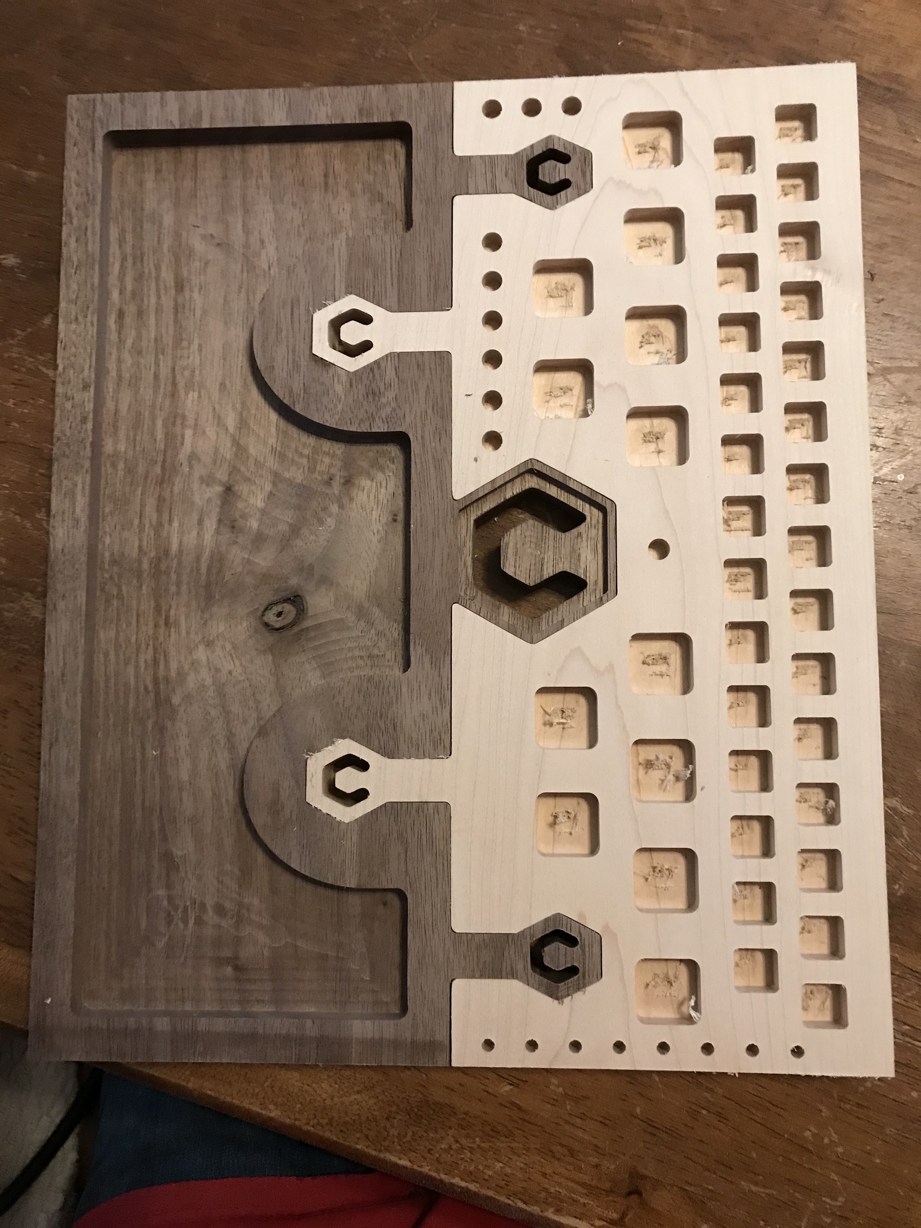
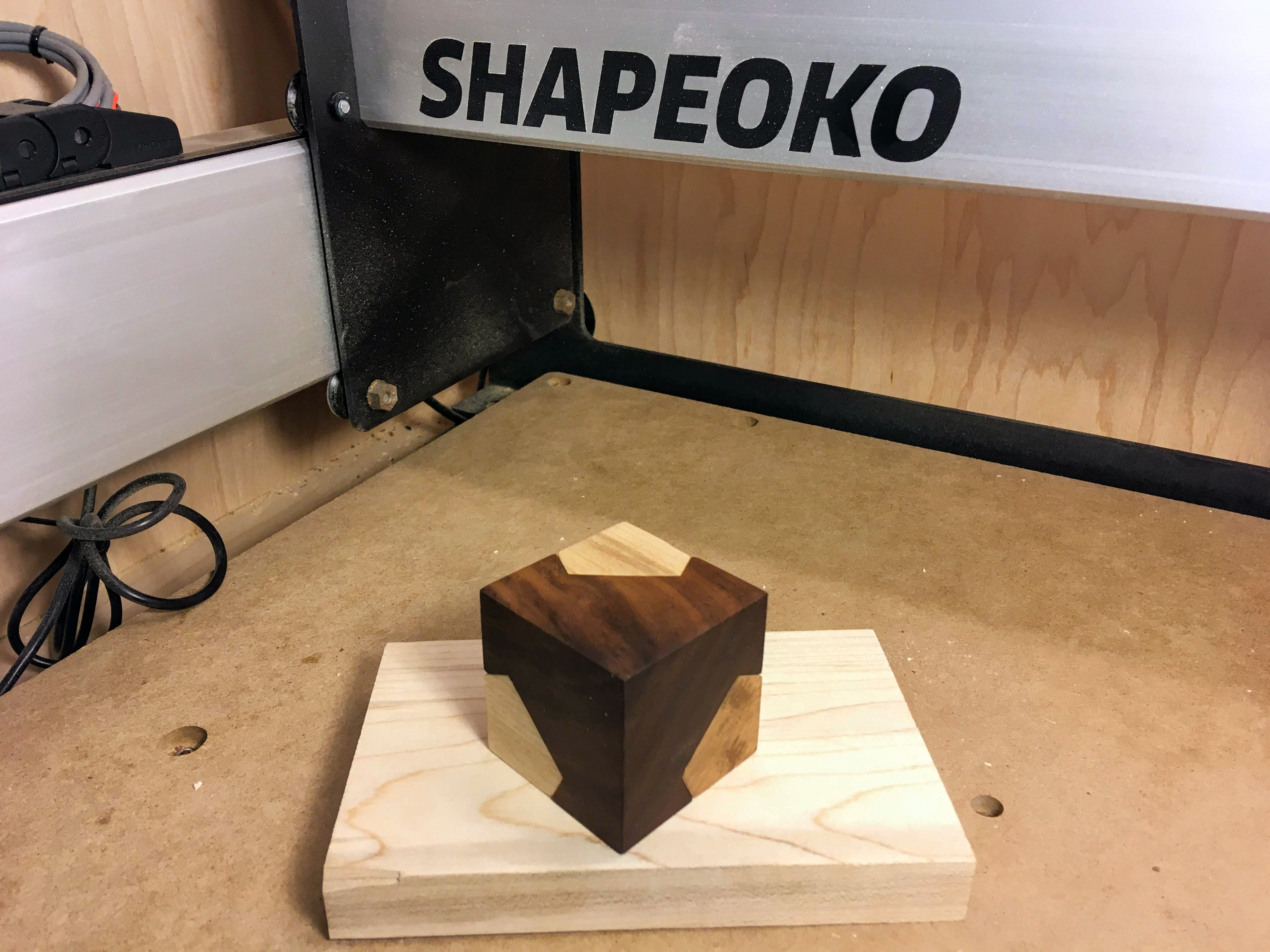
The real test for the design and machining would be here, will the last piece fit? :
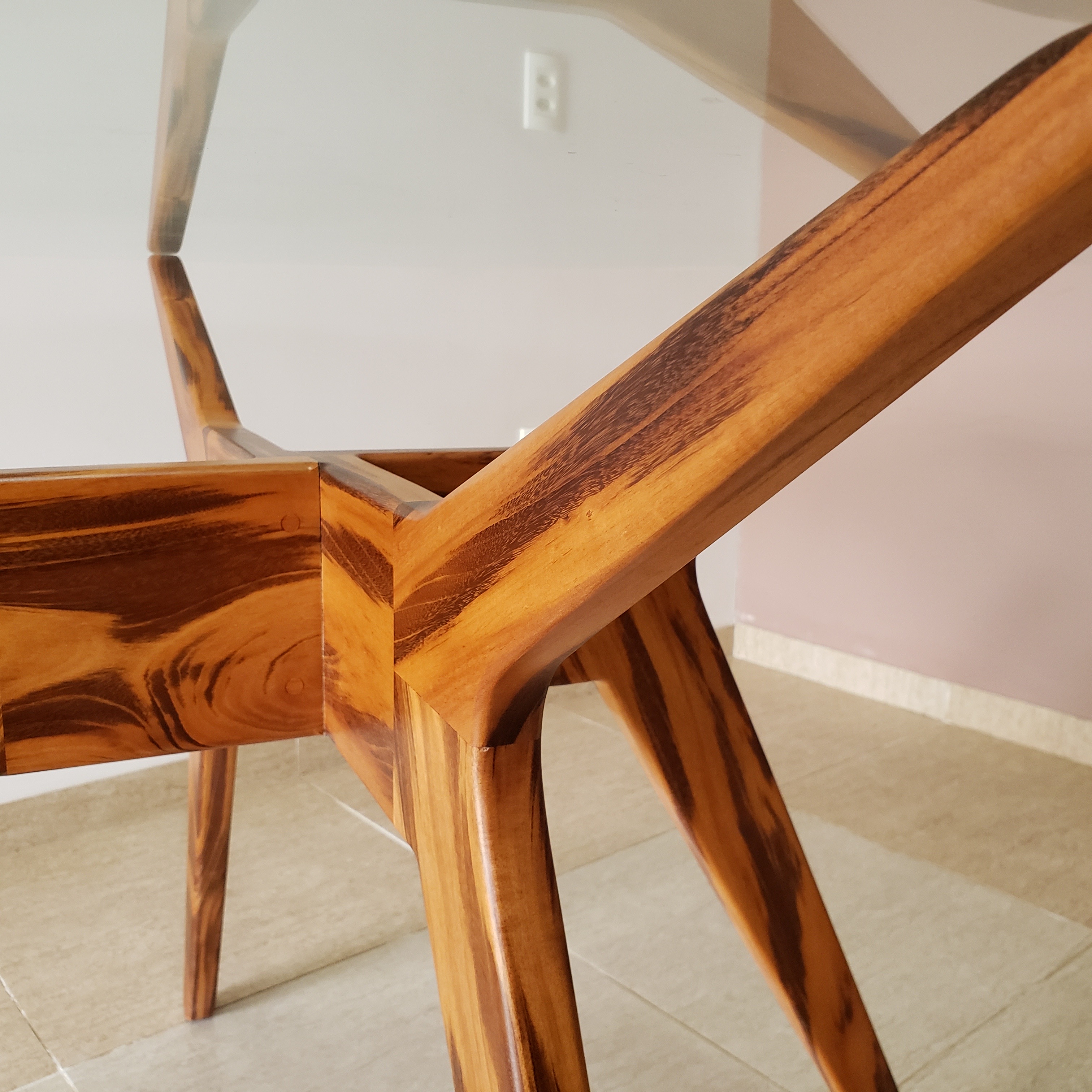
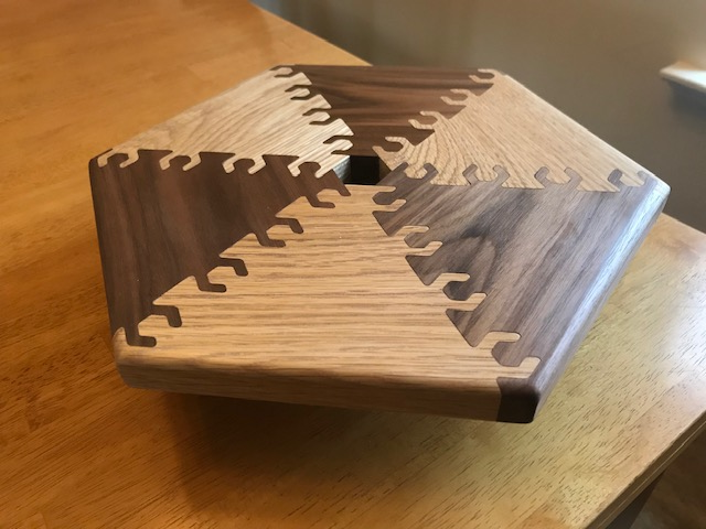
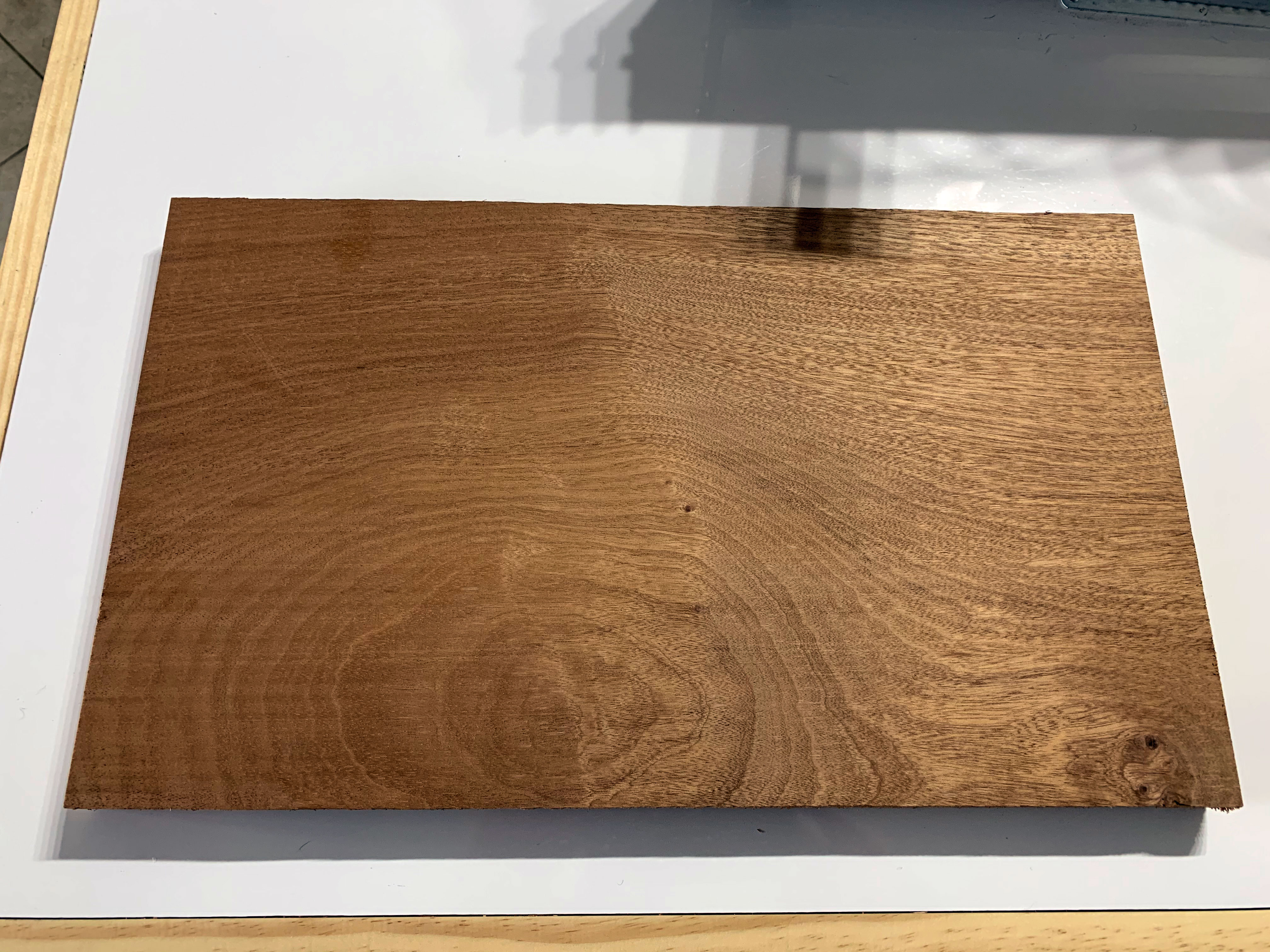
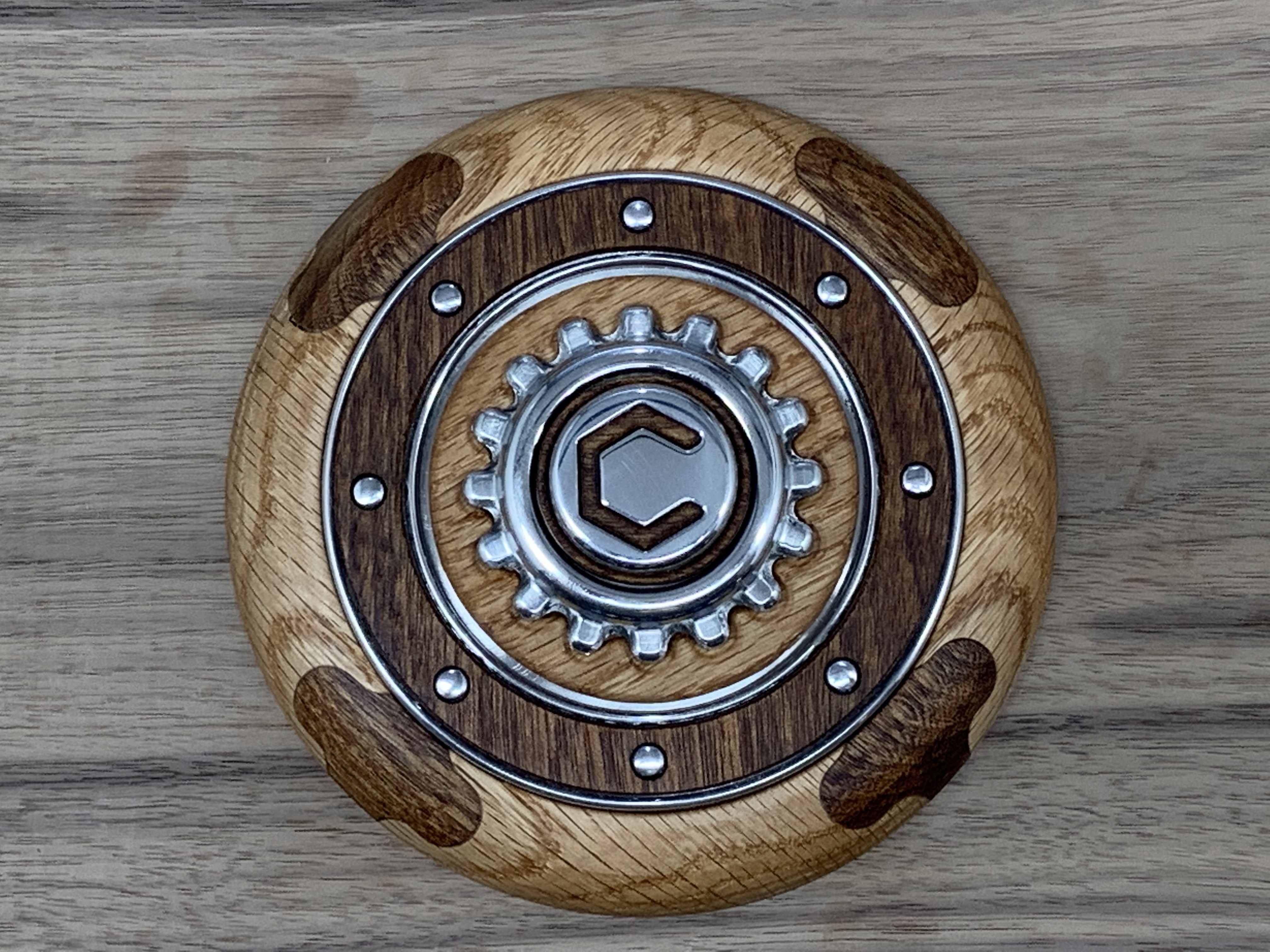
With only a few light taps with a block and mallet, success! This after the first finish coat of polyurethane:
7X5 60 Degree.c2d (1.3 MB)
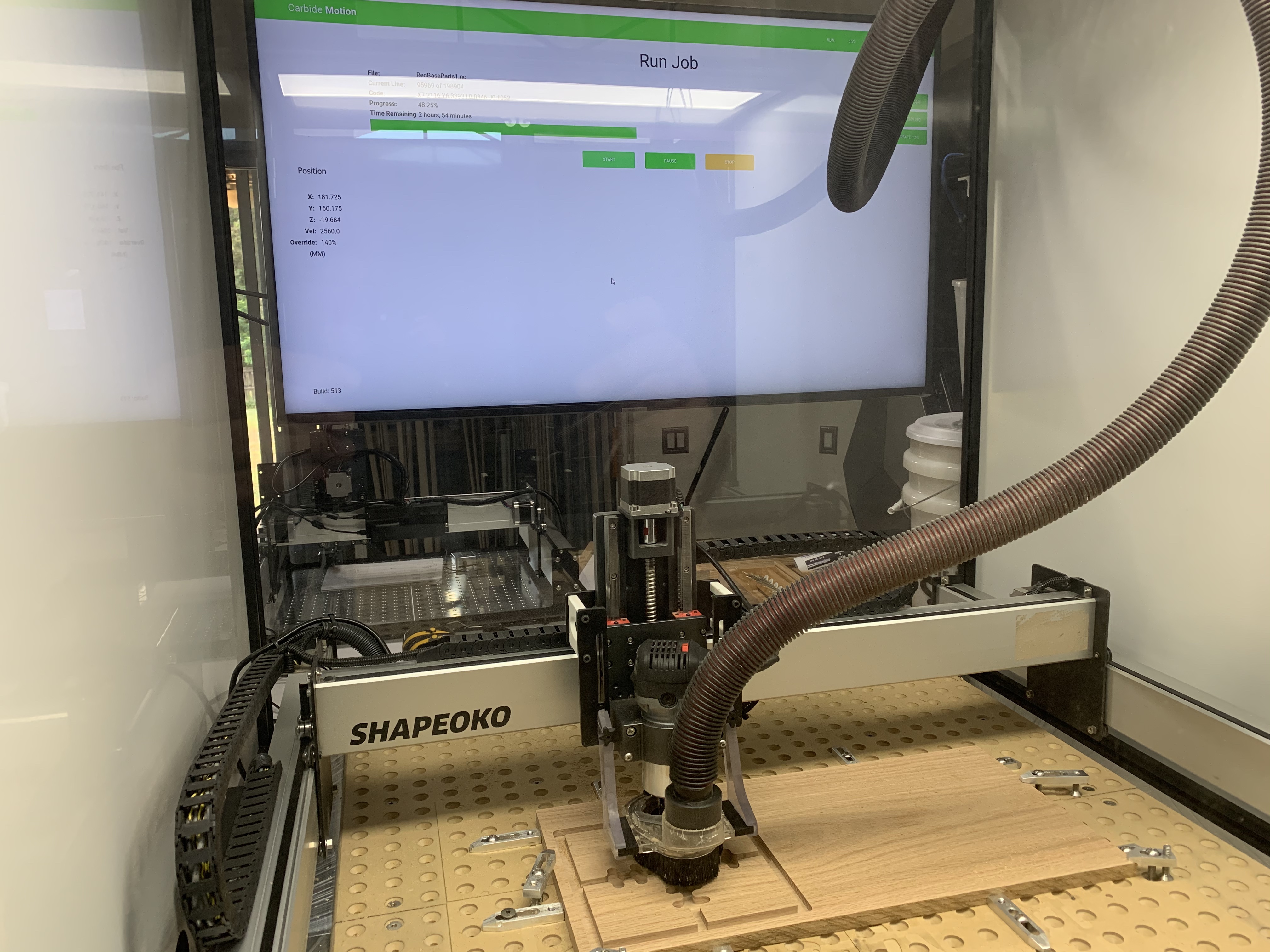


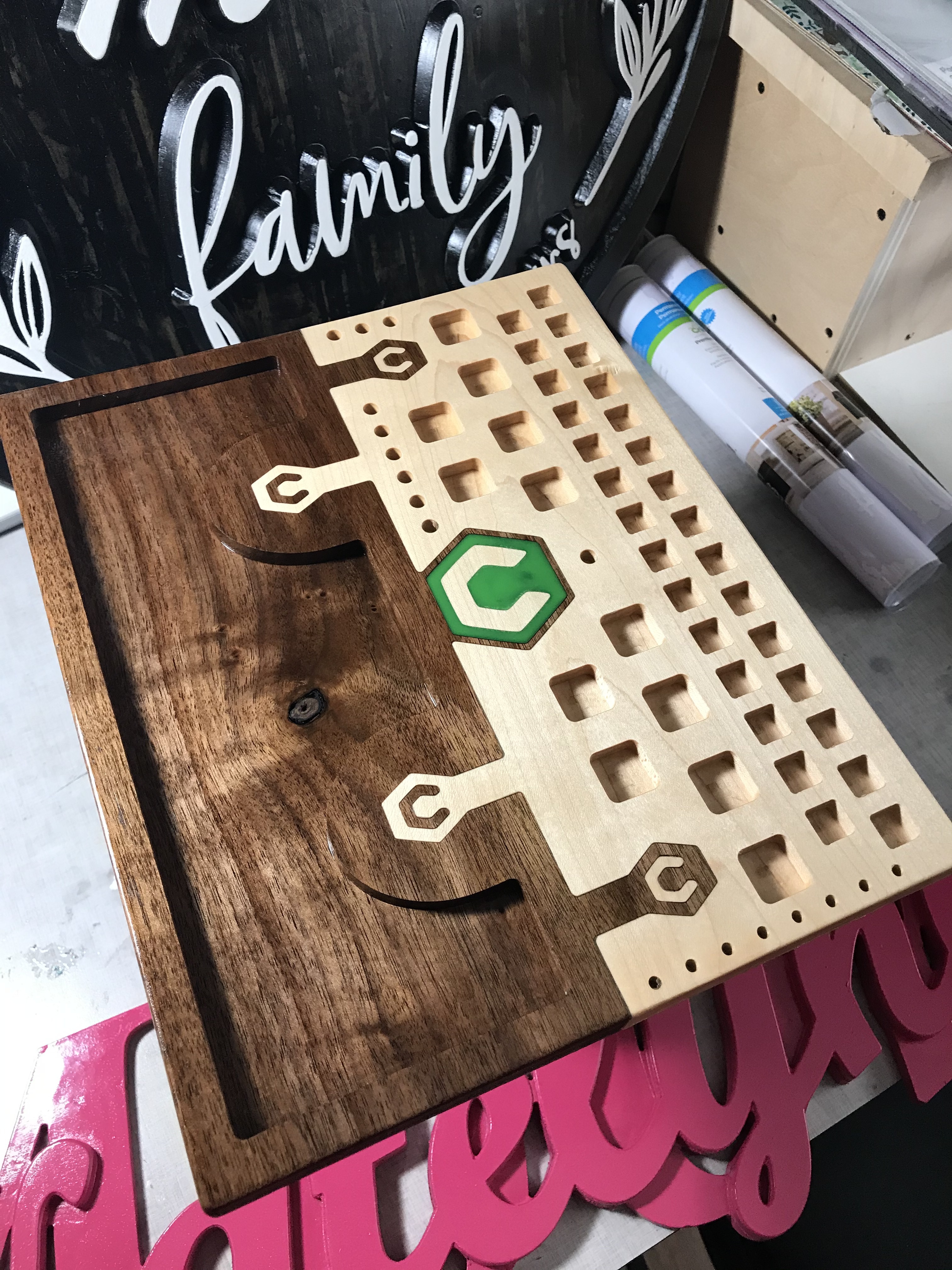

 …I then decided to split the file up into two steps so I could move the router up in the router mount to get enough height to clear away the corner material, and then back down and re-zero to do the pocket features.