Nice! How large is it and what material to you intend on using ?
My paranoid mind can’t help but tell you to keep an eye on that machine during that very long cut. Did you go with the default/recommended feeds and speeds in CC ? I wonder if it would be doable/useful to limit the 1/16th endmill finishing to a smaller area, i.e. draw a contour around the “non-flat” parts, to avoid having to spend time “finishing” the flat areas on the left & right sides ?
I have to second Julien’s comment, Can’t wait to see the finished! The mahogany should really stand out for this design.
Haven’t used CC Pro enough to know if the finish pass options have changed, but with Vectric you are able to combine passes at different angels which has a similar effect to using a smaller bit. The caveat of course is that the finishing time can be doubled.
Most of the issues here were self inflicted wounds. Not rechecking my zero after stopping for the night, damage to the project during clean-up, learning how to correctly scale model height, and not having a well planed piece to carve .
But, first 3D and first CC contest entered:
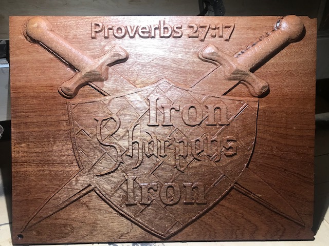
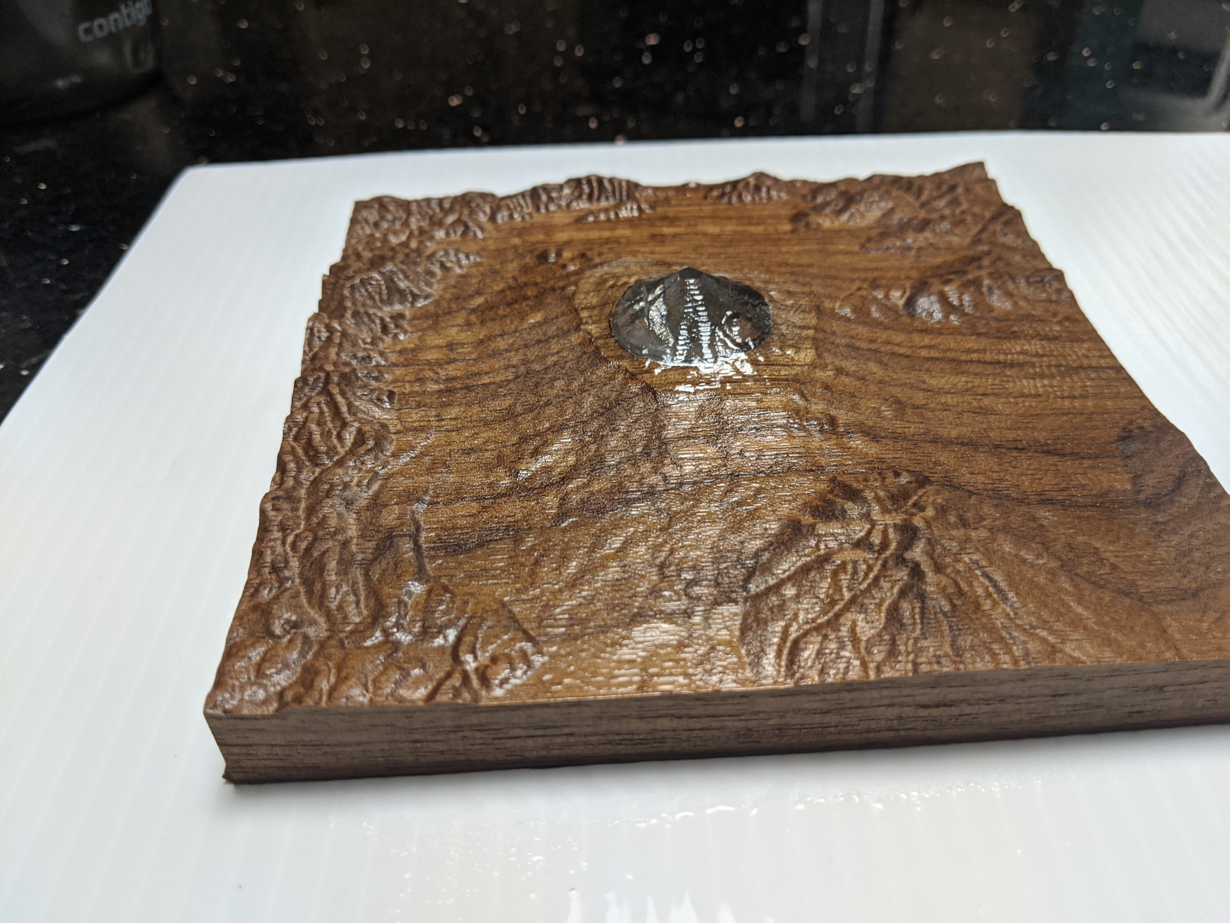
Finished with 2 coats of satin lacquer.
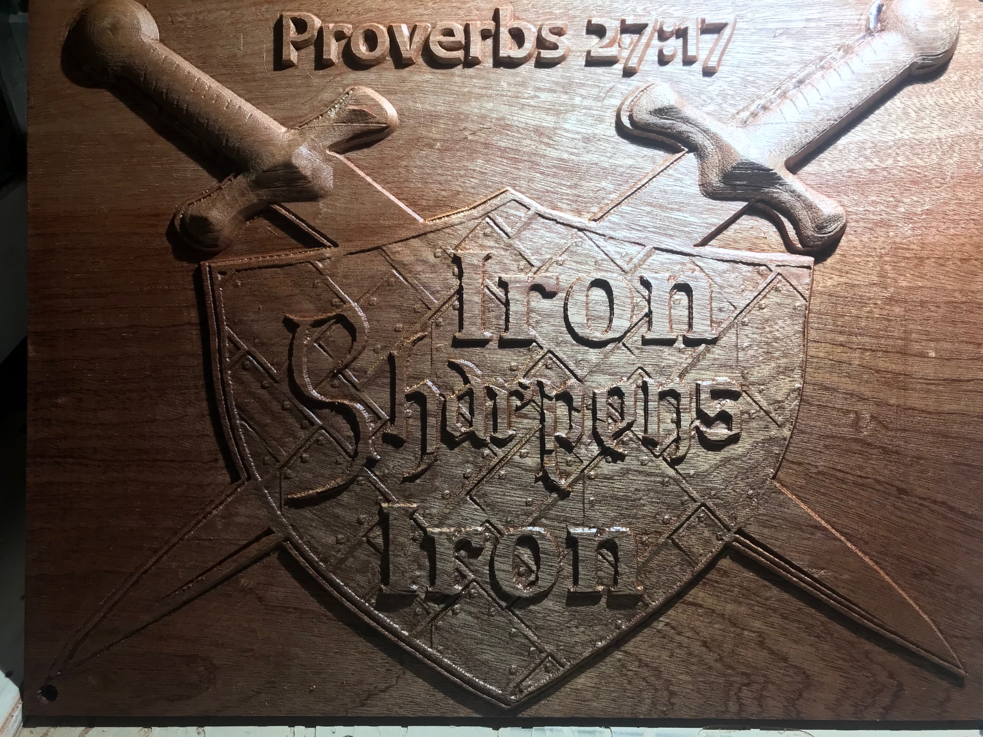
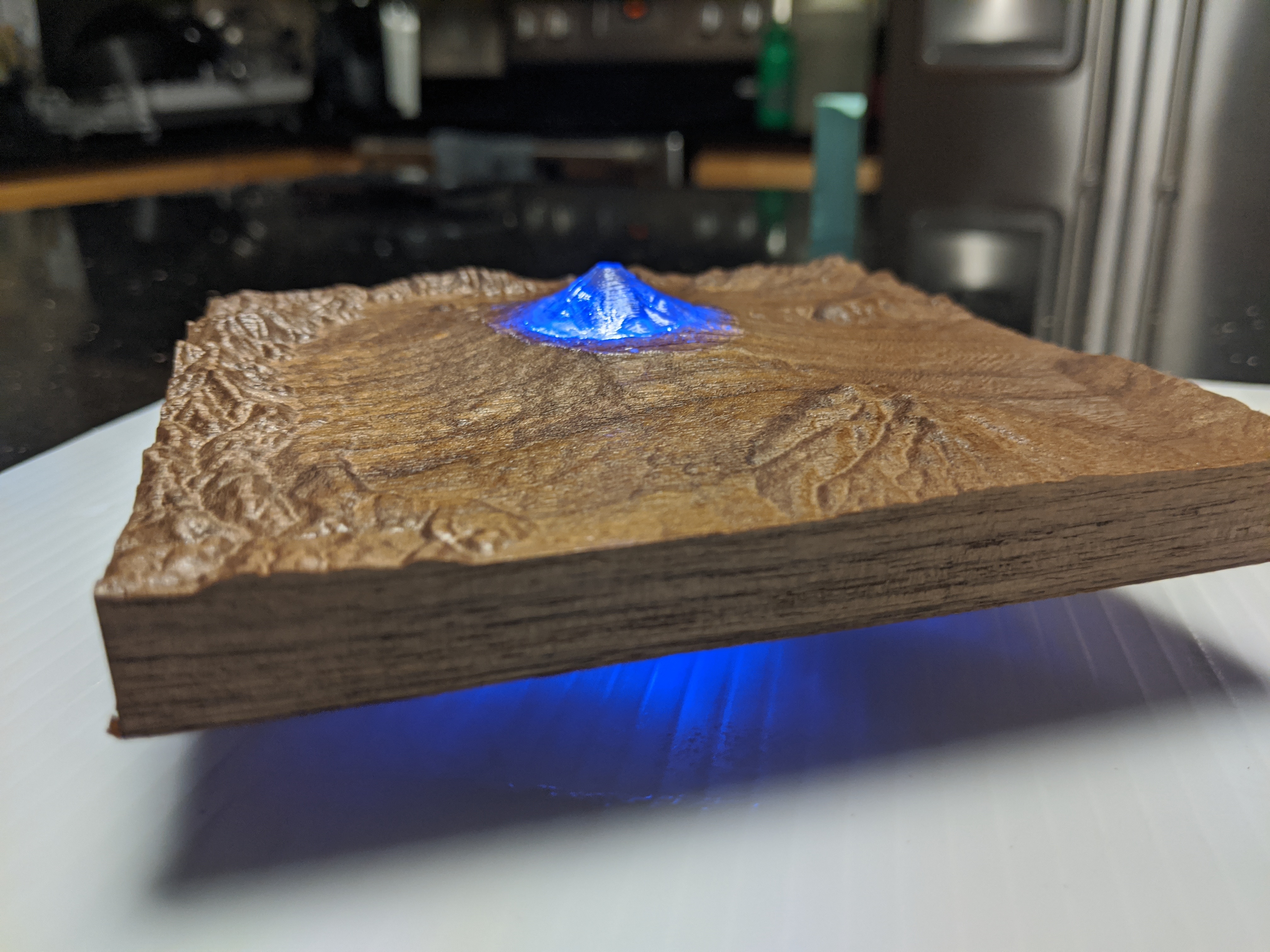
Dramatic lighting to show the detail in the shield.
I figured we’d have a bunch more topography in here by now.
I’m not entirely happy with how this turned out, but happy enough with it to post it. Also to share lessons learned.
Wall of text that you can ignore if you’d like:
I’ve wanted to do one but wanted it to be slightly different, or have another function as well. Initially I was thinking of taking a segment of the moon and using a crater to hold a coin (like the Apollo 11 50th anniversary coin). Eventually settled on the idea of making a feature light up. So I picked Mt Fuji as a test template since it has a feature that is singular without much else in the way (think about like trying to pick out the lake in crater lake and how hard that might be).
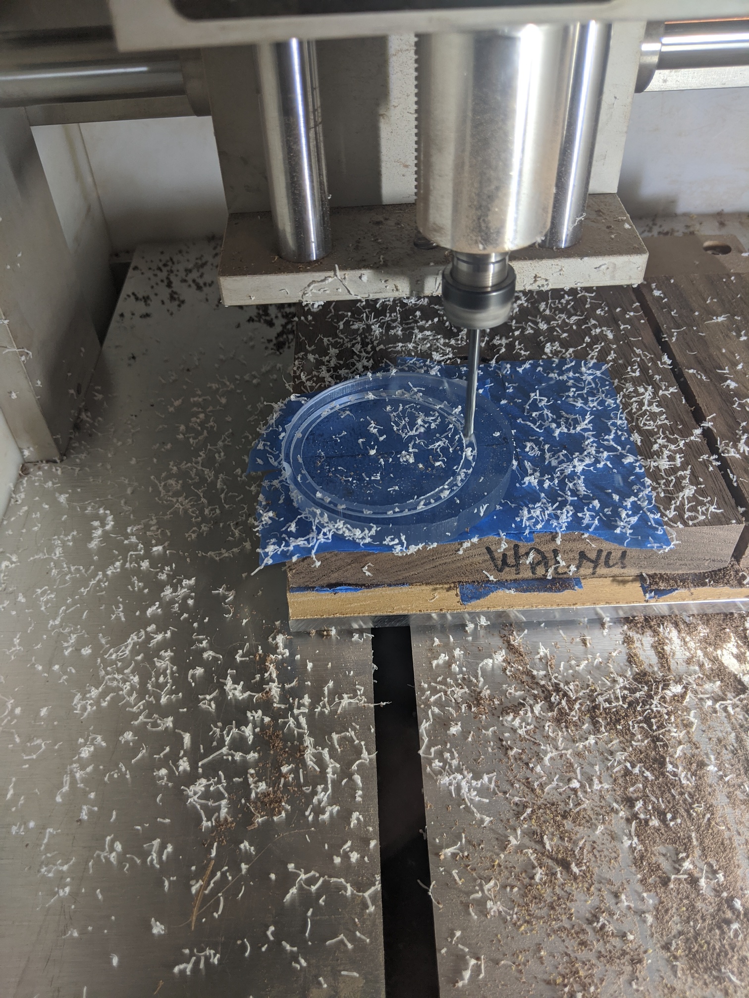
I picked out some walnut for the project since I had a bunch that was in a random size scrap box. Also had some cast acrylic that was 9.3mm thick that came from the scrap bin at the makerspace from a while back.
Grabbed the grey scale terrain from the website Winston mentioned in the video: https://tangrams.github.io/heightmapper/#10.12533/35.4271/-220.9006
Cut it down in whatever paint program I had on Windows, then brought in the object in carbide pro.
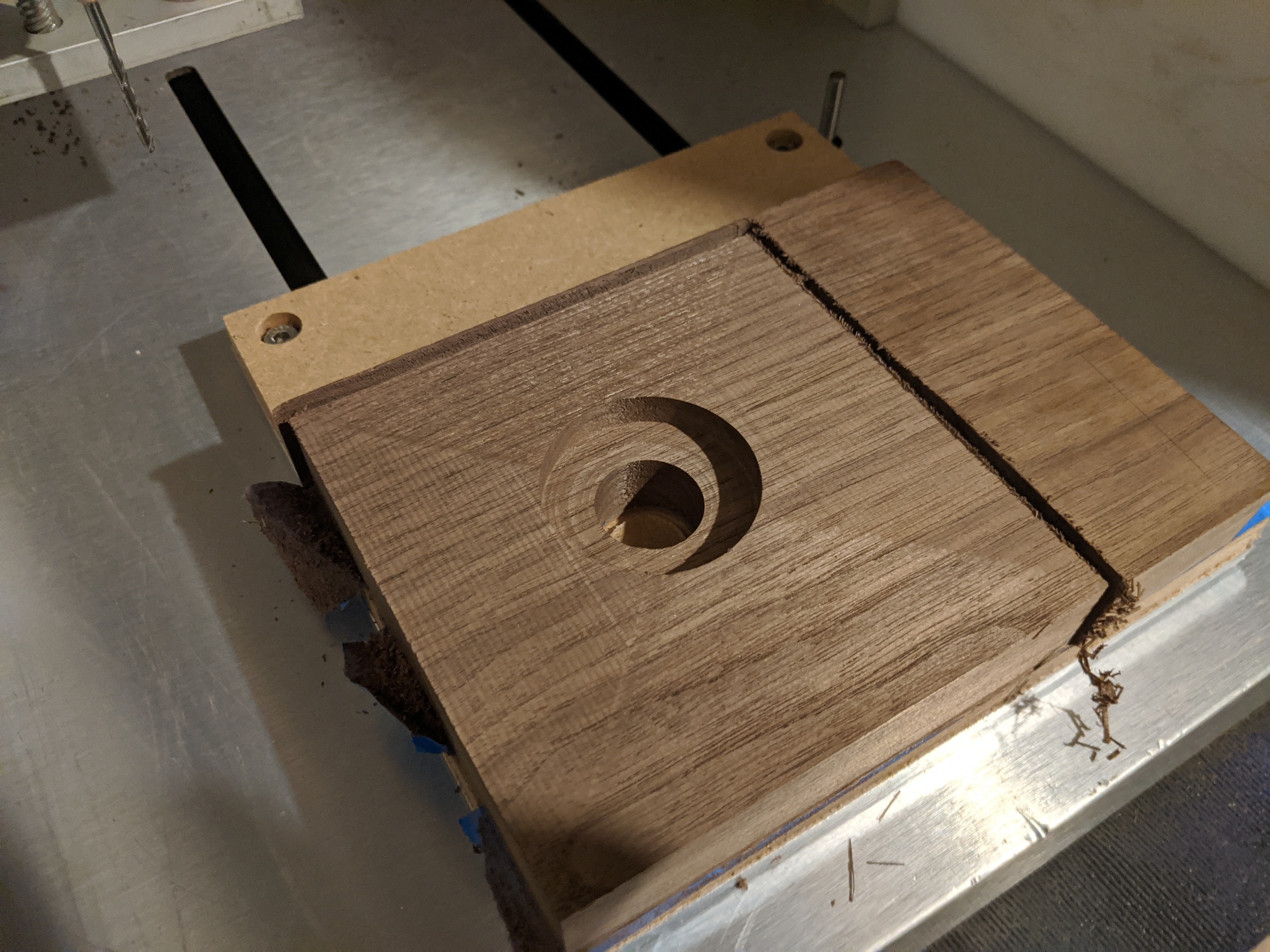
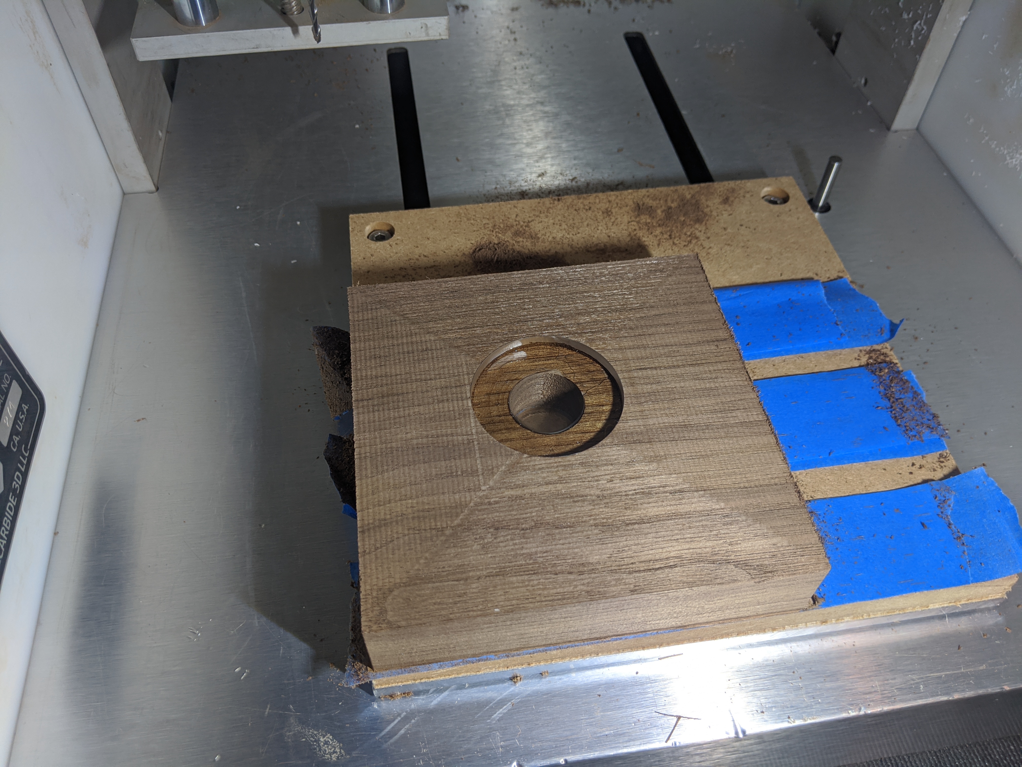
I also made 2 circles. The first was a light channel. I didn’t actually measure but I envisioned getting a tea light type thing in there. Second circle was for the acrylic to be recessed in here. I’m sure I could’ve done math or something to figure out how large I actually needed the circle and how much of the mountain would be acrylic. Ideally it would look like the peak was covered in snow. But planning stuff out was not a mood I was in at the time, so we’re in guestimation territory.
Then I used super glue to bond the acrylic to the wood.This may have not been the best. Or maybe used a more runny super glue. This one is I think more gel like.
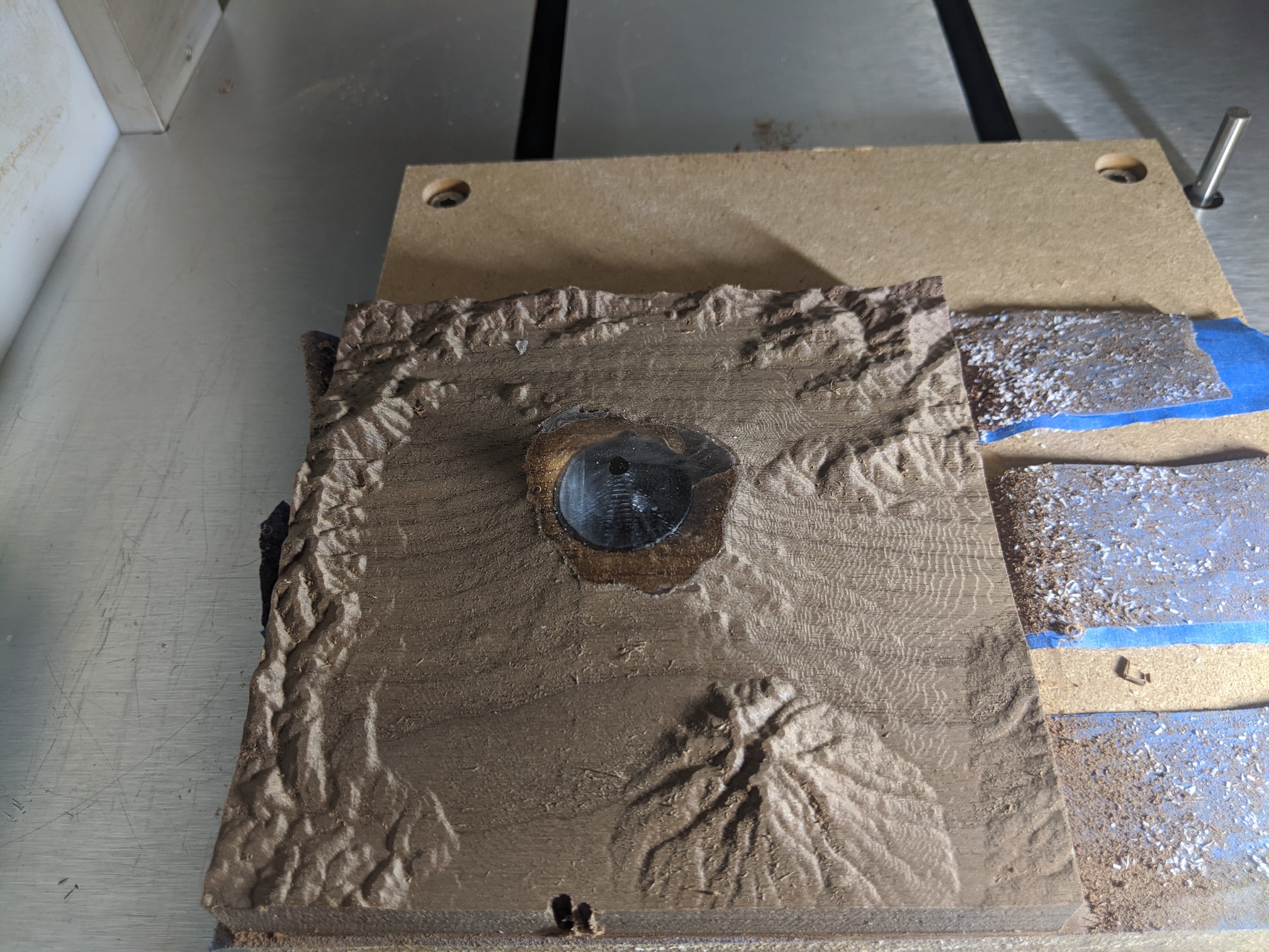
Then I setup different roughing paths in carbide create. The circle I used to pocket the acrylic used acrylic speeds/feeds, then used hardwood for the rest.
A few lessons learned. I think I’d like to do a smaller light hole, and make this a 2 sided operation if I were to do it all over again. Pocket a hole for a tea light and then punch through with a smaller hole to the top for the actual light itself. Smaller hole for the light would allow me to have the acrylic start higher up on the mountain, which I think would give the mountain a more snow peak look.
Also maybe would want to use a translucent acrylic instead of the clear. The clear acrylic has a very obvious line between the where the acrylic ends and where the wood starts.
I think this is a fun idea to play with. One of the other versions I’d like to do is New Zealand, where the islands would be the acrylic and the ocean would be a wood. There’s also room to glue two pieces of wood together and have the top layer of wood be the total height for the topography, which I may try next.
I also made the box size smaller to exclude the bottom middle section that had indents. Mt Fuji.c2d (174.9 KB)
@4NineDesign: I think it came out great, love the texture on the shield. And the little imperfections go along quite well with the overall “rough” look of the piece. Not everyone’s first 3D job looks as good as this!
@Radiation: oh boy this does not help me put my Nomad craving under control
Definitely an interesting approach and something to explore. When I use clear acrylic and backlight, I usually leave some space to fit a strip of white plastic diffuser (the ones they sell for LED strip lighting), to…well, diffuse light more evenly. Looking forward to seeing that New Zealand piece ! (as a 2nd entry maybe ? )
So I get confused by the licensed images… so I guess I’m asking is a free image licensed, and by saying no licensed images that means it has to be made by us, meaning no internet pictures or images… am I correct on this thinking I just don’t want to submit something that is not approved
You can absolutely use images from the internet if…you are reasonably confident that they don’t have a copyright or some kind of license that restricts their use, and makes them non-shareable. The tricky part sometimes is figuring out whether they do…
In Google images there is a filter for that.
One easy counter-example is the famous Star Wars calendar, or anything else Disney for that matter.
My point was mainly, if you are going to post a file which contains vectors/images you downloaded from somewhere, make a reasonable effort to check that it’s ok to use and share them (both to meet the forum rules, and to keep yourself out of trouble, should be the evil troops of Disney lawyers decide to raid the Shapeoko forum )
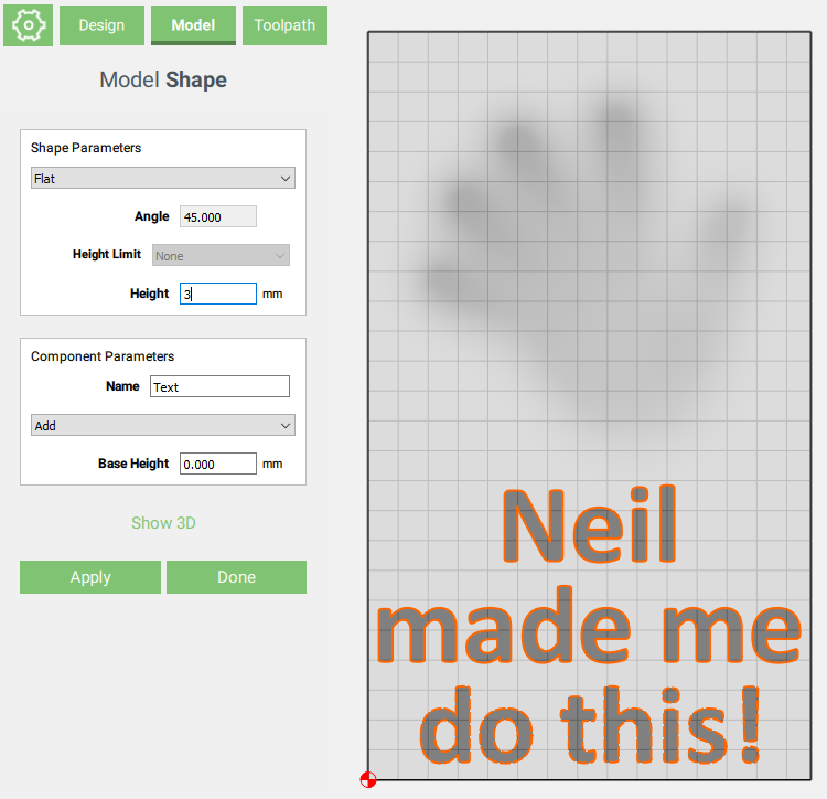
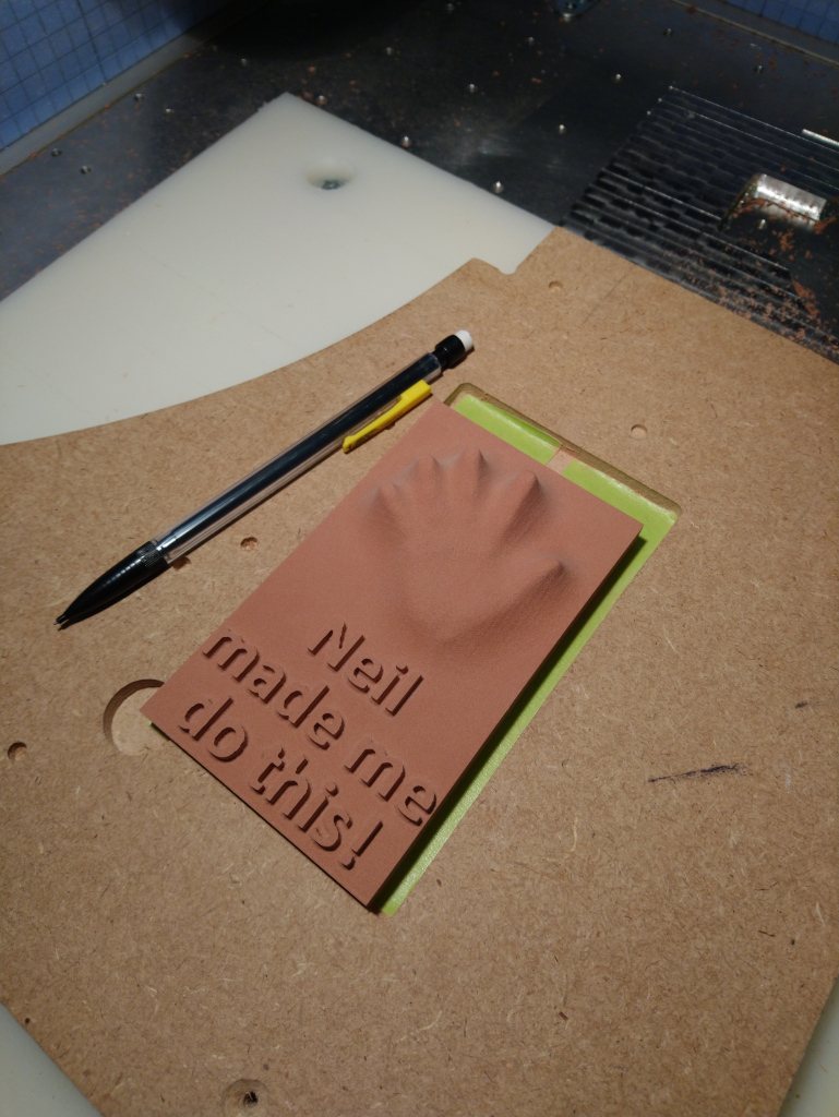
In the spirit of honouring @neilferreri’s dare AND hopefully documenting in the process how easy it is to do a simple CC Pro project, here’s my non-eligible-contribution-slash-CCPro-tutorial:
Ever since the announcement of the Nomad2020, I have had a severe case of Nomad craving, so I figured I would pretend I have one and use my Shapeoko to mill something small and detailed.
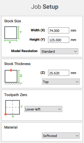
I stumbled upon a block a Renshape that had been collecting dust since I got it in a package from C3D in late 2017, so now was as good a time as any to use it! It’s about 5"x3"x1" (and I measured it to be precisely 73.7mmx124.5mmx25.62mm)
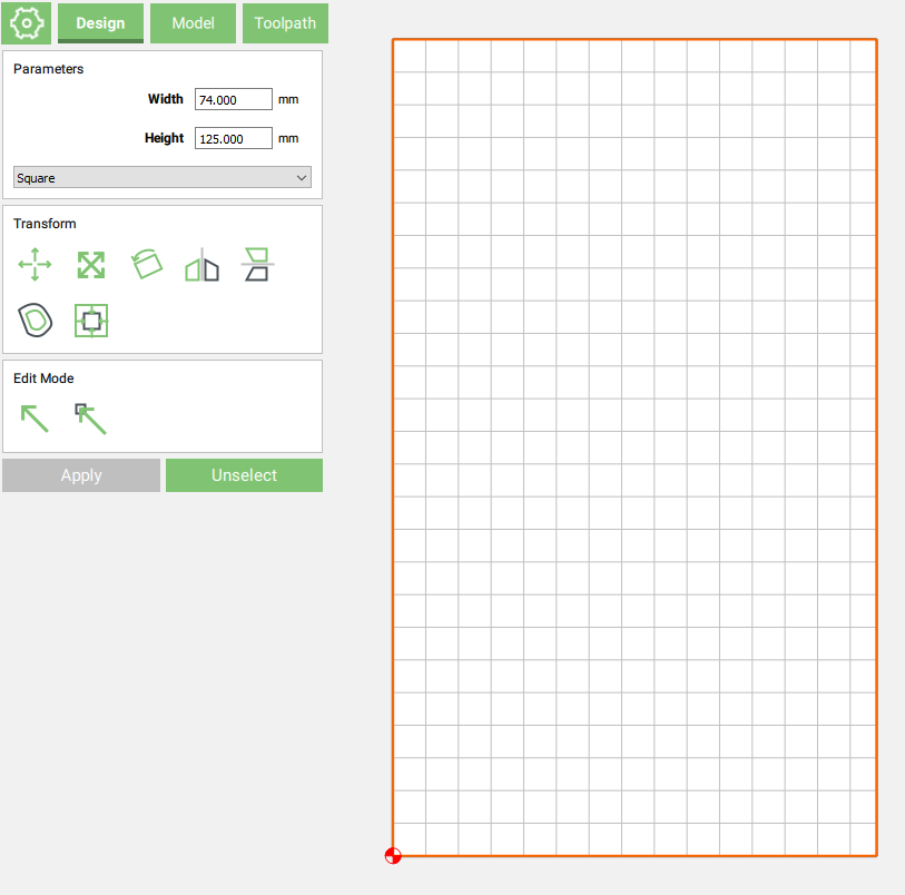
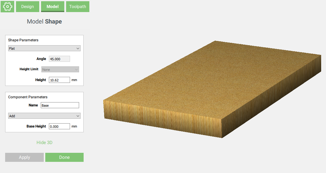
I created the project in CC, entering a stock size a tiny bit larger than the dimensions I measured on the renshape block:
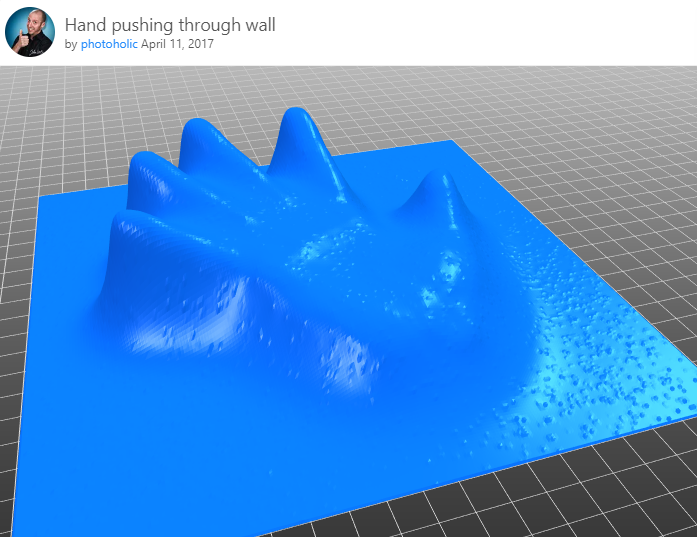
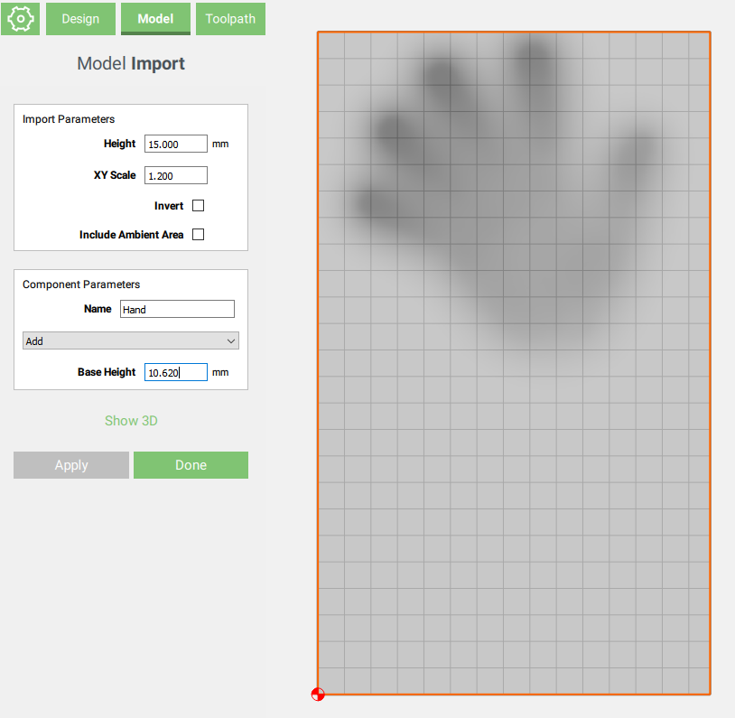
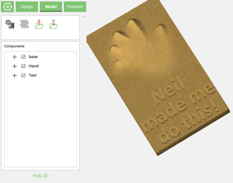
I wanted to use this opportunity to try @fenrus wonderful STL to greyscale PNG heightmap converter, and random browsing led me to that 3D model I liked on Thingiverse:
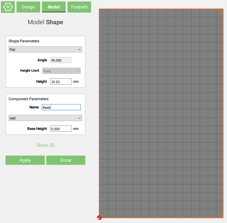
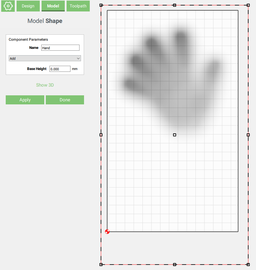
I then adjusted the image position a bit (and yes, I cheated a bit and padded the image generated by the converter so that it extended over the whole surface of my stock)
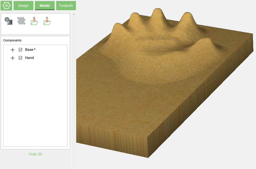
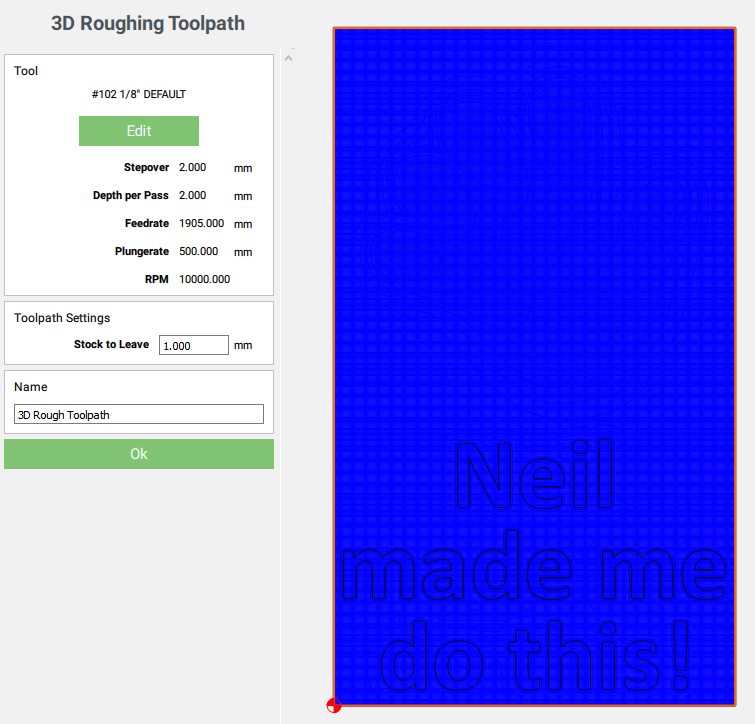
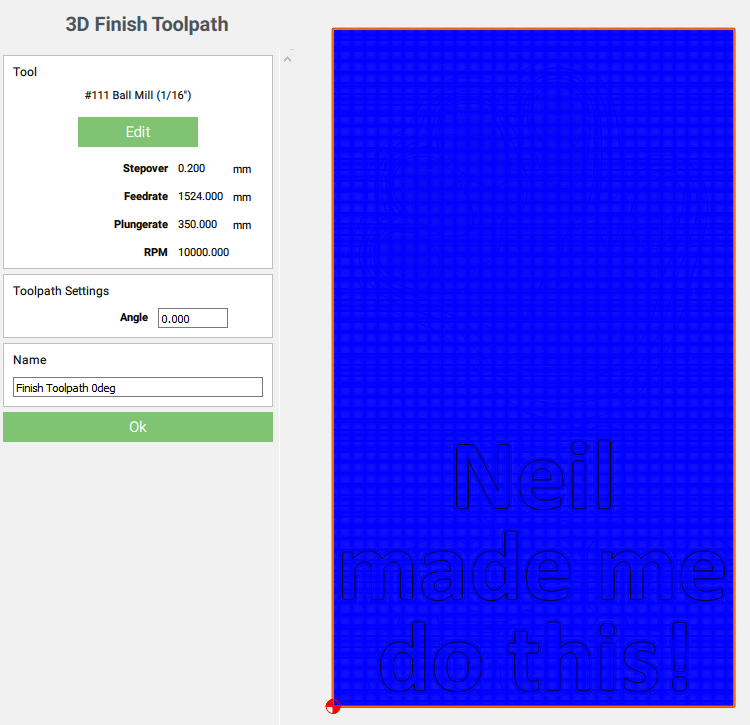
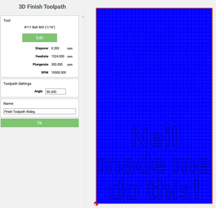
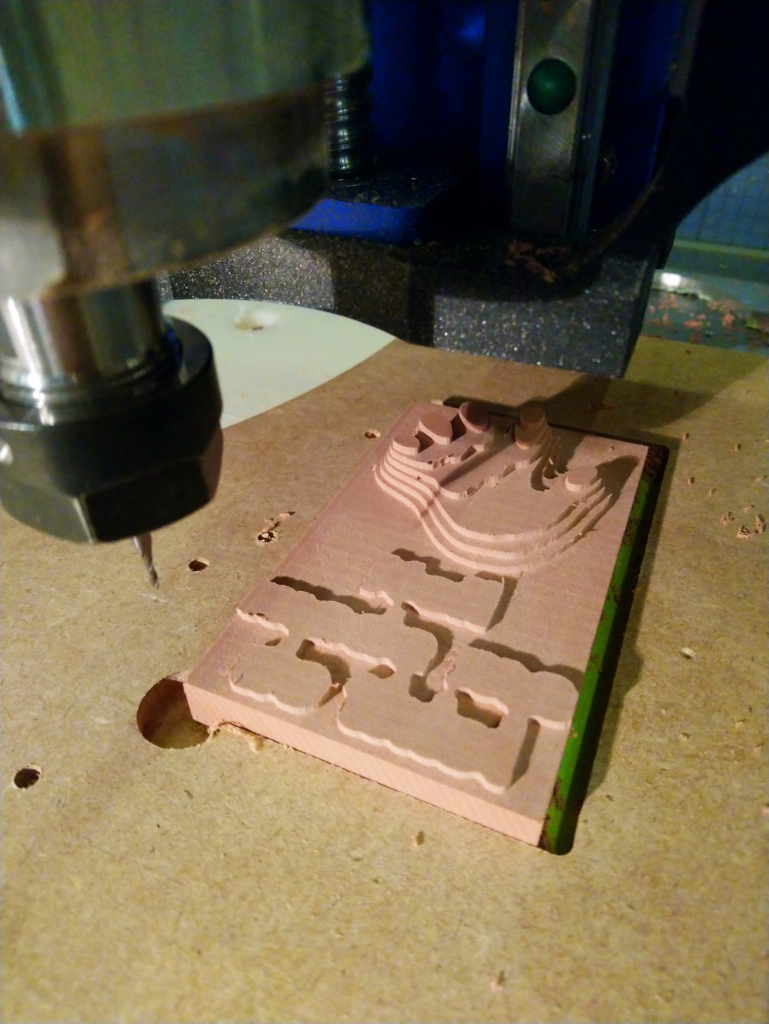
I proceeded to create the toolpaths, first the 3D roughing toolpath using the outer bound, with a #102 1/8" square endmill (that’s 75ipm / 0.08" depth per pass and stepover):
I would not be using Carbide Motion this time (mostly because I have an unsupported probe that I wanted to use for corner probing), and I wanted to have to ability to stop and check things between the toolpath runs, so I decided to save each toolpath to a separate file. I used CNCjs and @neilferreri’s macros to still benefit from the BitSetter for tool changes.
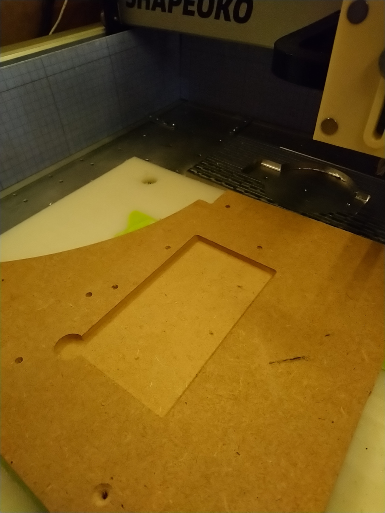
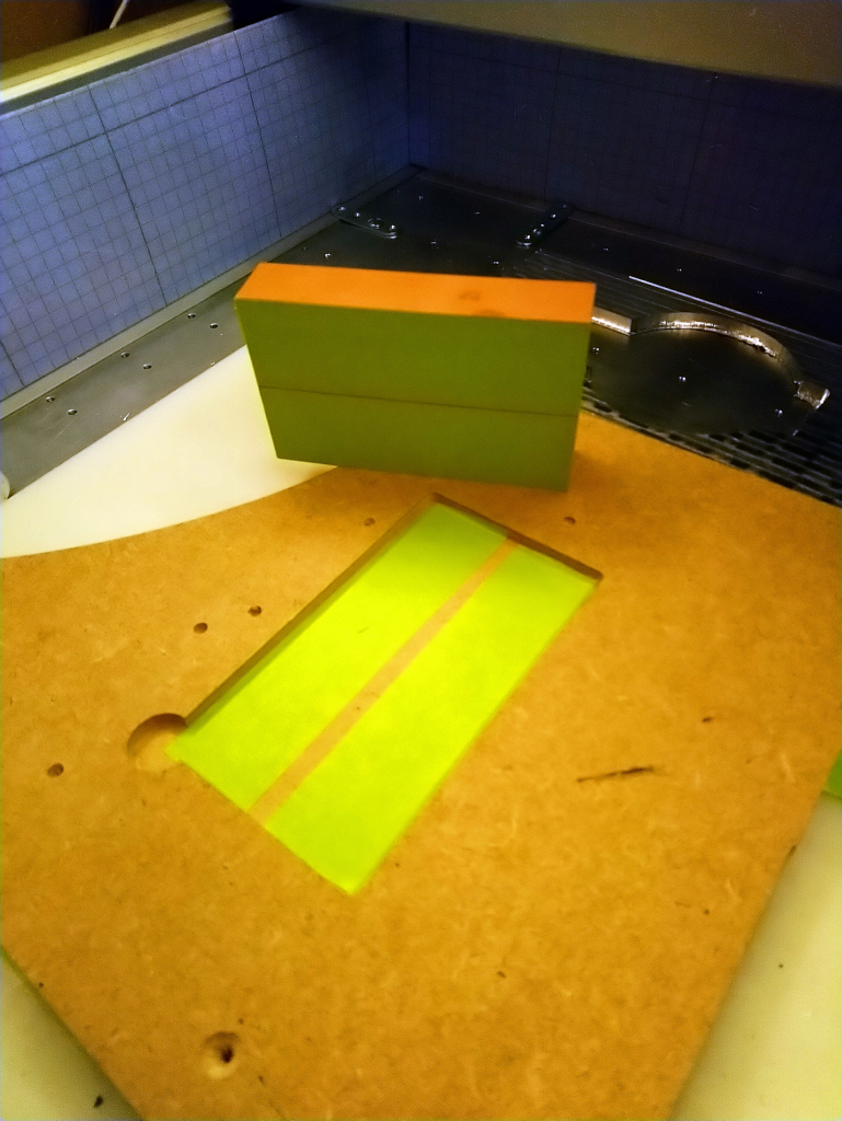
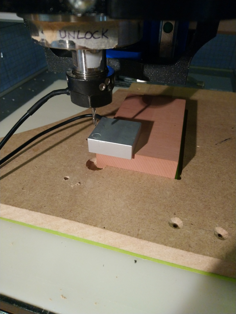
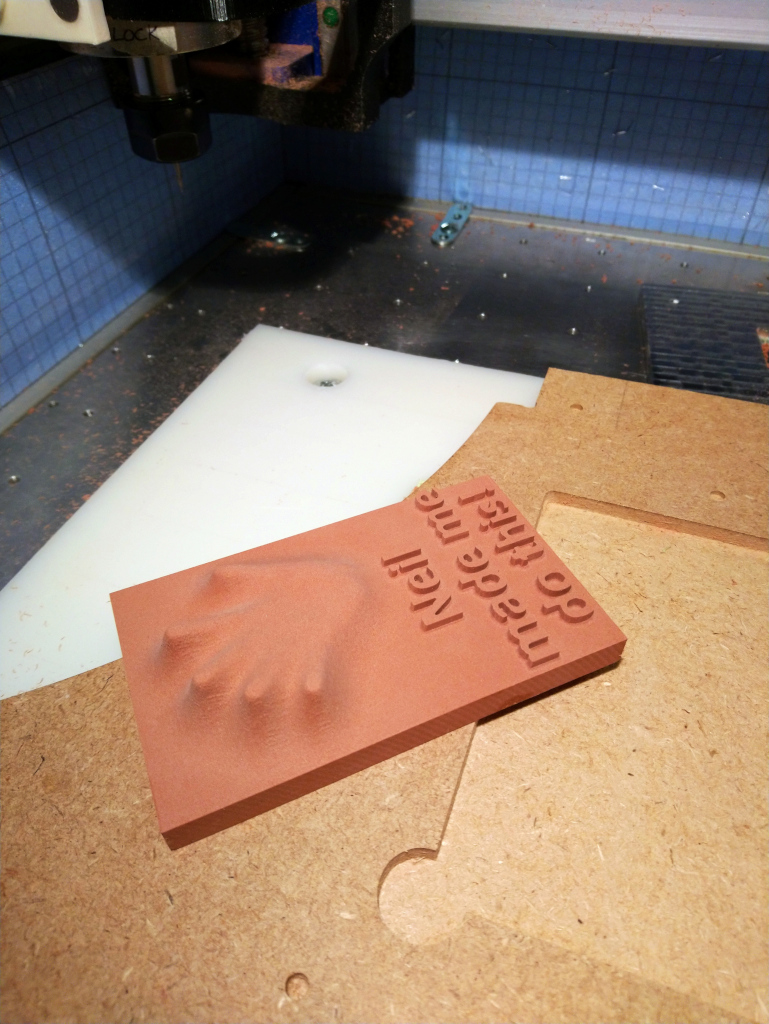
Since I would be milling material from a stock of exactly the size I had setup in CC with no margins anywhere, I decided to cut a jig in MDF for positioning the Renshape stock while being sure that it would align perfectly with horizontal and vertical axes of the machine
side note: I used just a few drops of CA glue for this job, as I did not want to risk breaking the piece of Renshape after the cut when prying it away, and since there would be very little forces on the stock during the cut anyway.
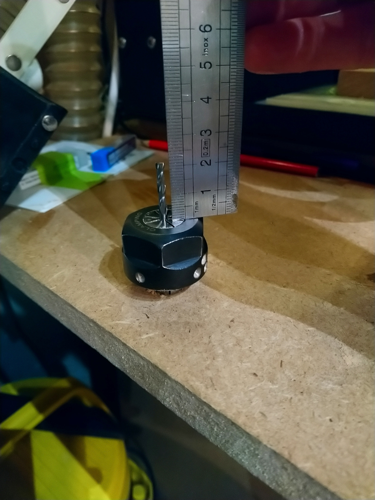
Quick check that my 1/8" endmill was sticking out enough from the collet to be able to mill 15mm of material:
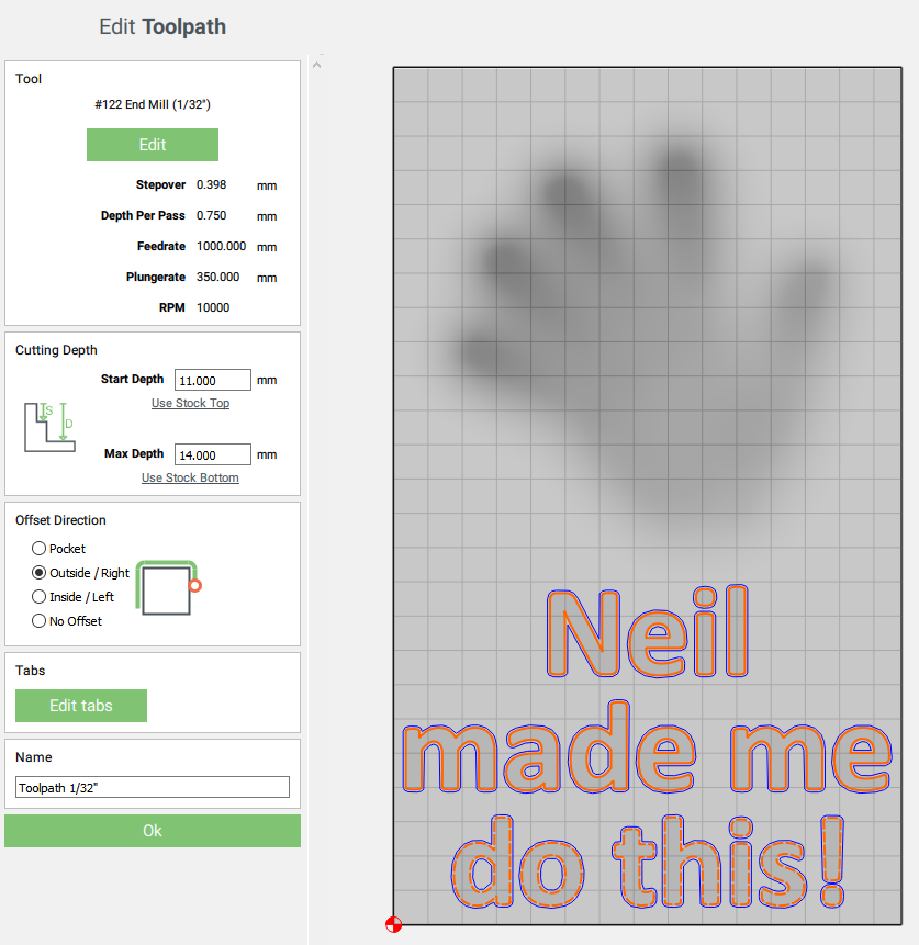
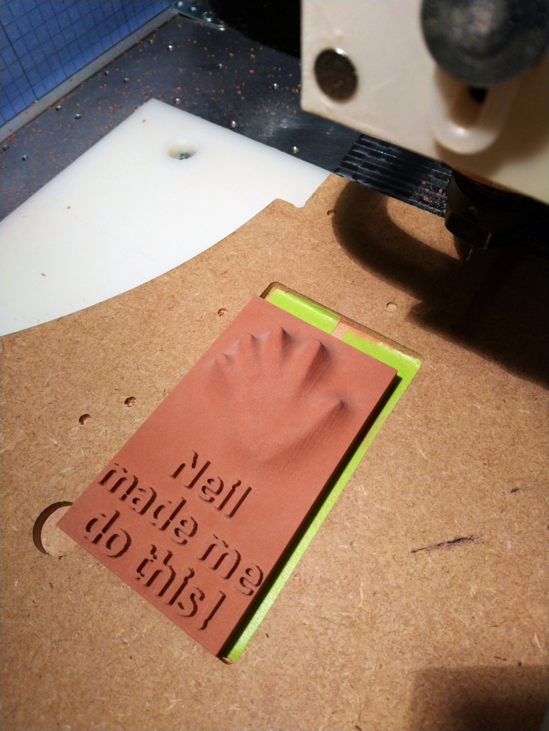
Finally, I installed the #122 1/32" square endmill to get the smaller details in the text. It always feels scary to see that tiny 1/32" endmill go down on the BitSetter…but it works.
There you go. Oh my, Renshape is so easy and satisfying to machine, I have a newfound passion for it. Shapeokos should ship with a few blocks of renshape for beginners I think ! Much more rewarding than everyone’s first cut in pine/fir.
I showed you mine, you show me yours now ! One more week to go to submit something in the challenge.
I have had good results even with “flat” cutters, say 2mm… if you have relatively simple geometry even a flat cutter works great… (just do 2 finishing passes, either 90 or 45 degrees offset from eachother)
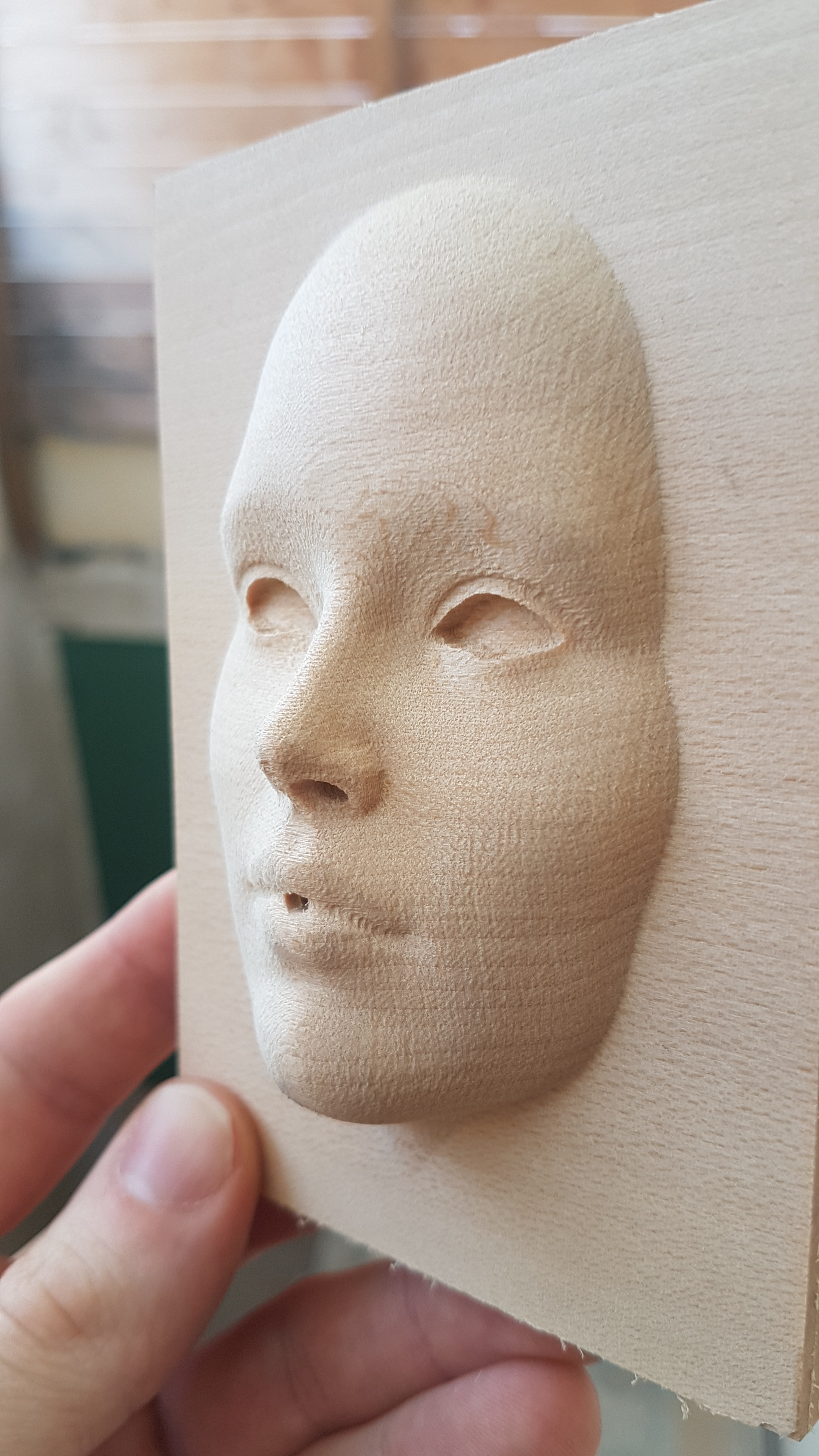
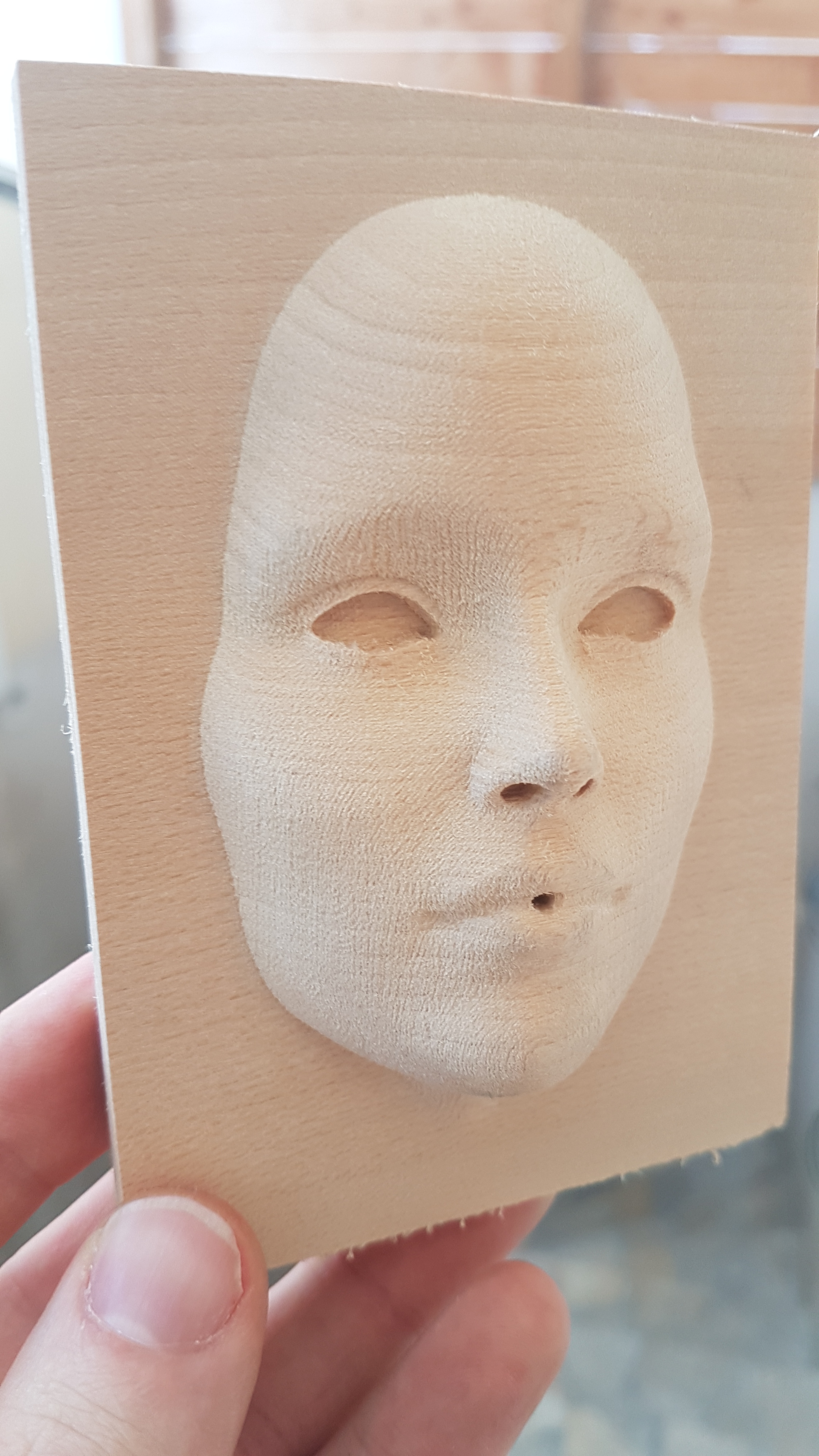
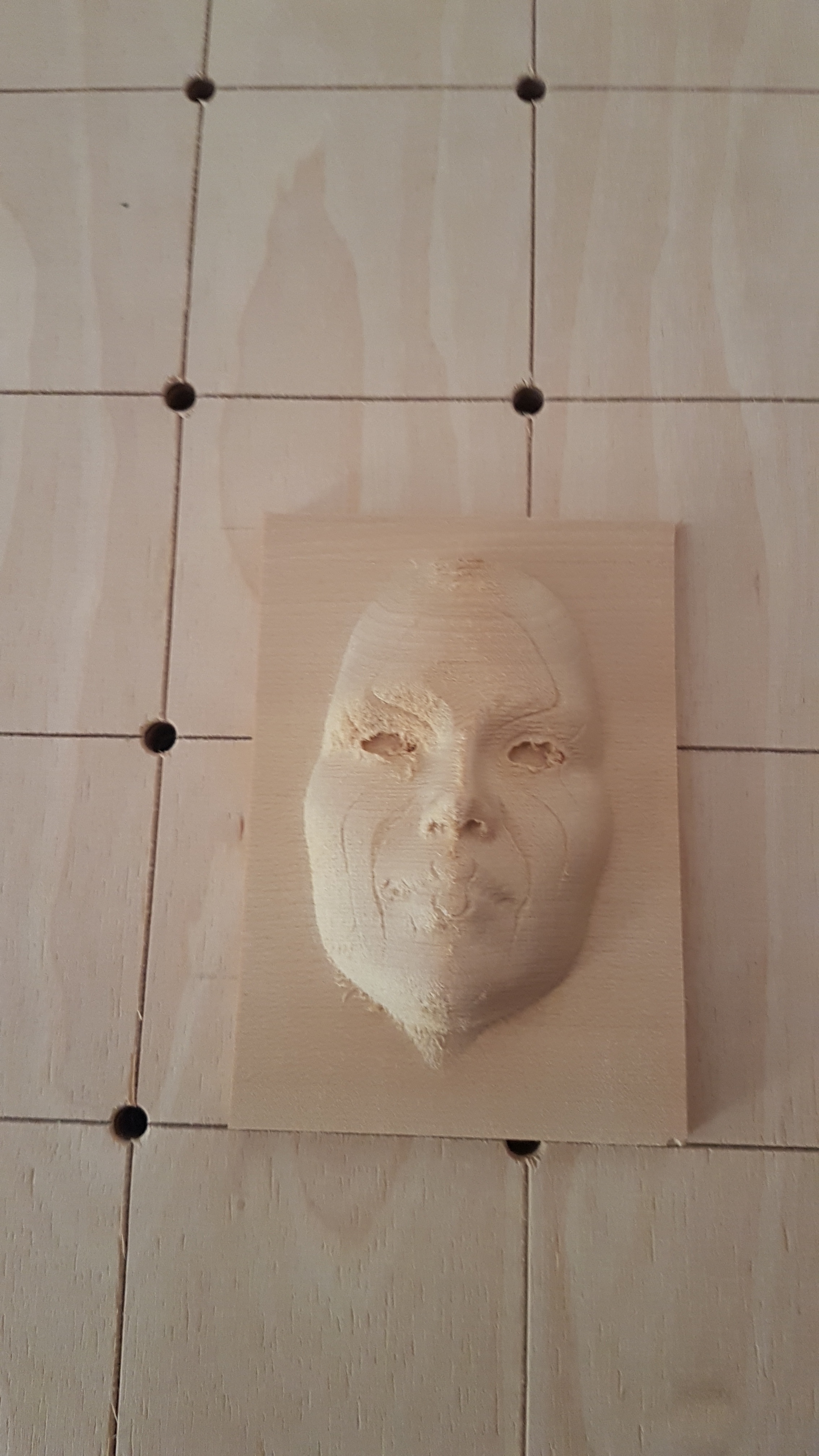
Hello, this is my little 3d project for the challenge.
It allowed me to learn how to use Carbide Create pro for 3d.
And I found it fun. And also to check what Julien says, a Shapeoko can be as accurate as a Nomad
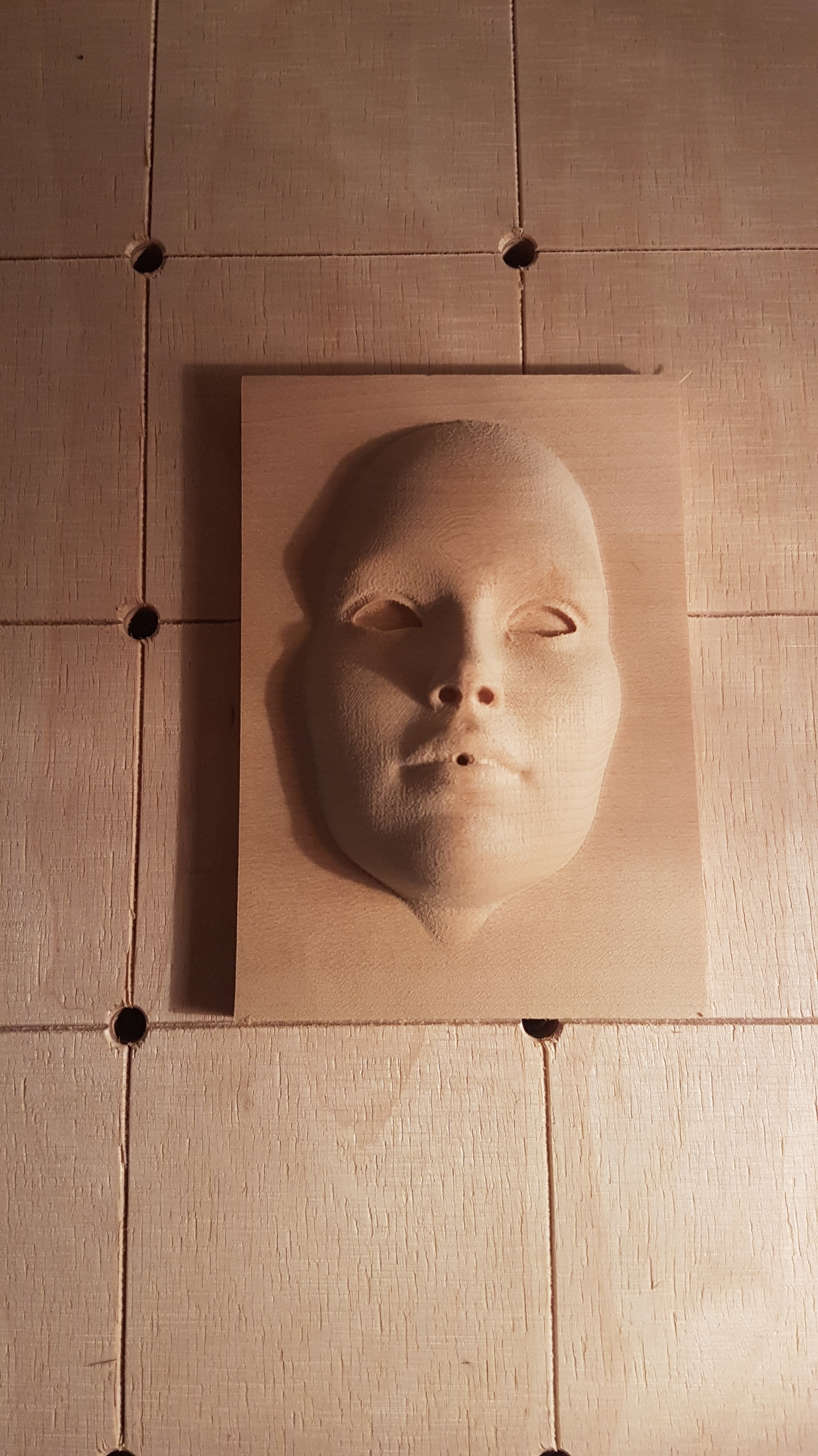
Finish toolpath:0.8mm
Feed rate :1000mm/min
Spindle speed: 12000 rpm
plunge rate: 200 mm
Woc: 0.3mm
depht per pass: 0.4mm
In two passes, the first on X, the second at a 45° angle.
and the result is superb.
I made a mistake, on CC, I put the reference surface at the top, not easy to point the Z, after the first pass. I played a trick
To memorize for the next times. face.c2d (90.4 KB)
Thanks for your entry @Bwood34, nice job and greay way to join the community !
Now we just need someone with a Nomad to enter the contest just to prove you wrong on that accuracy statement:
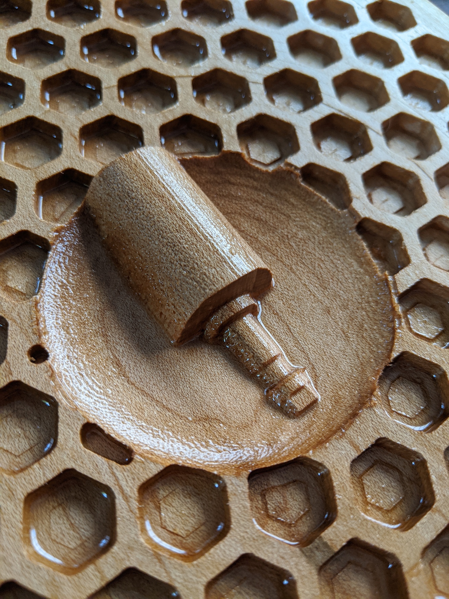
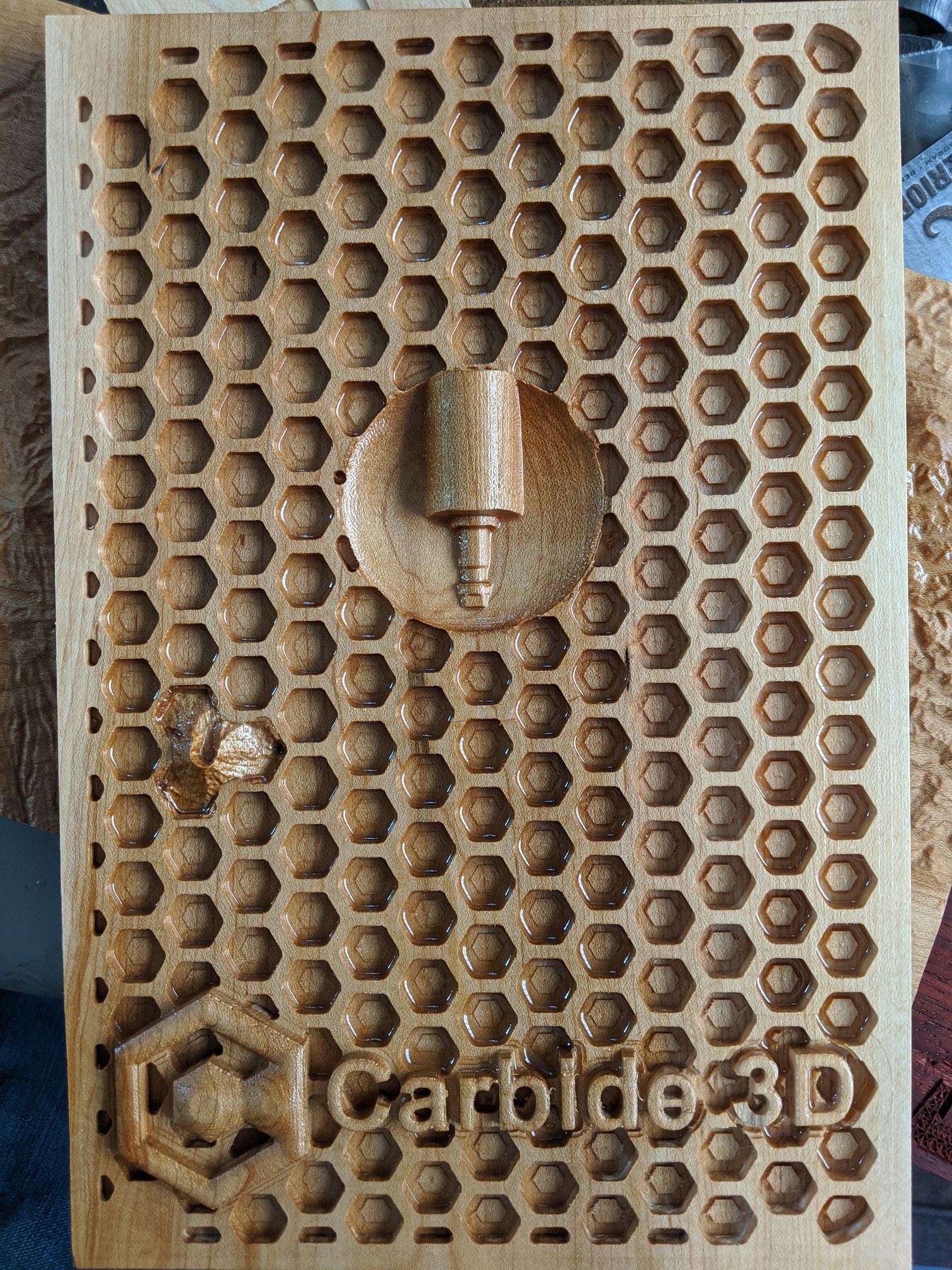
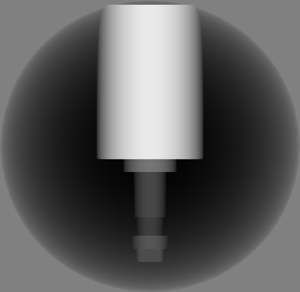
On thingiverse I found an STL model of a simple spindle: https://www.thingiverse.com/thing:3790264
I had to add 2 features to STL2PNG to be able to use this model, so that took some time, but I’m happy with the result:
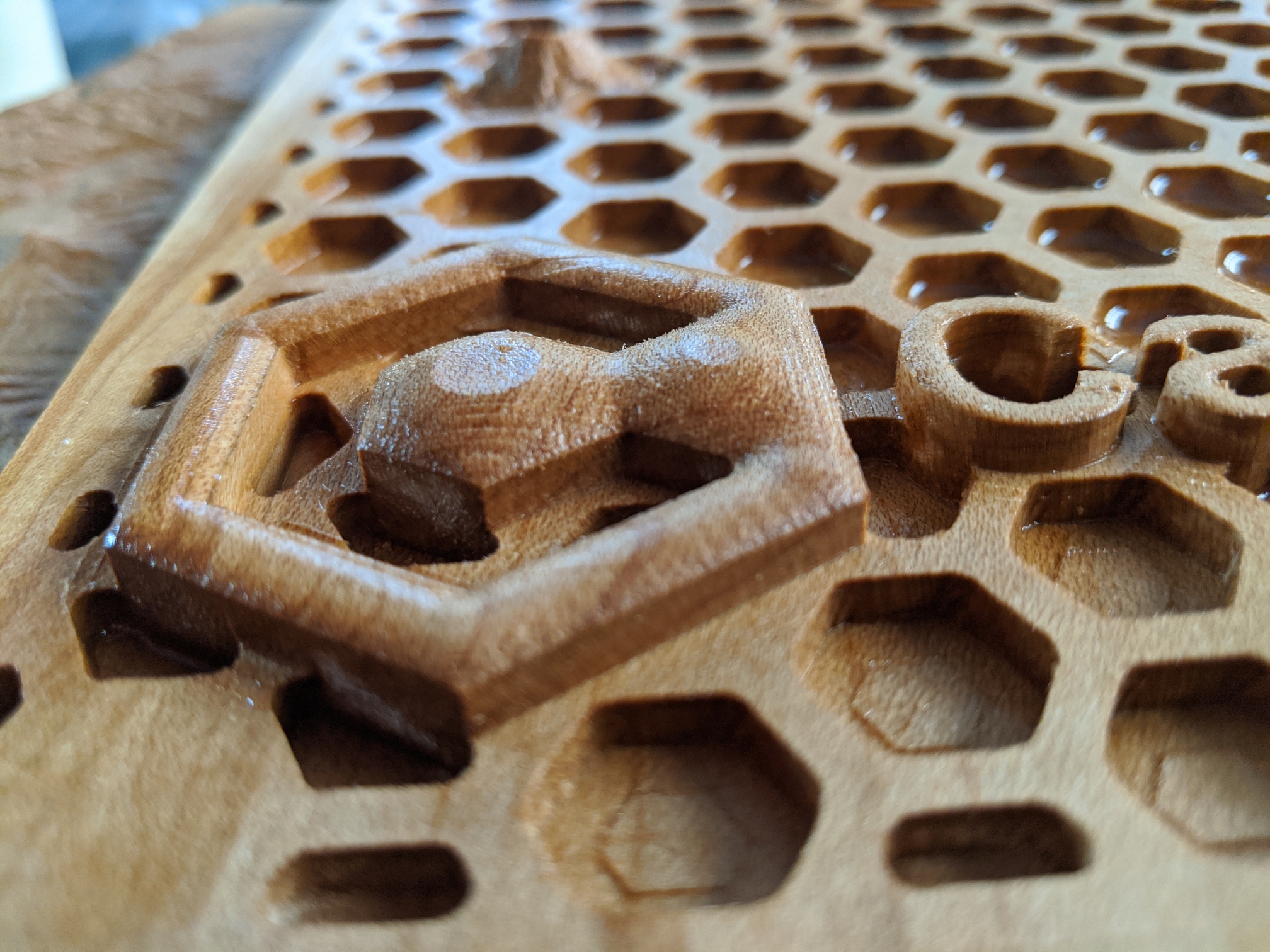
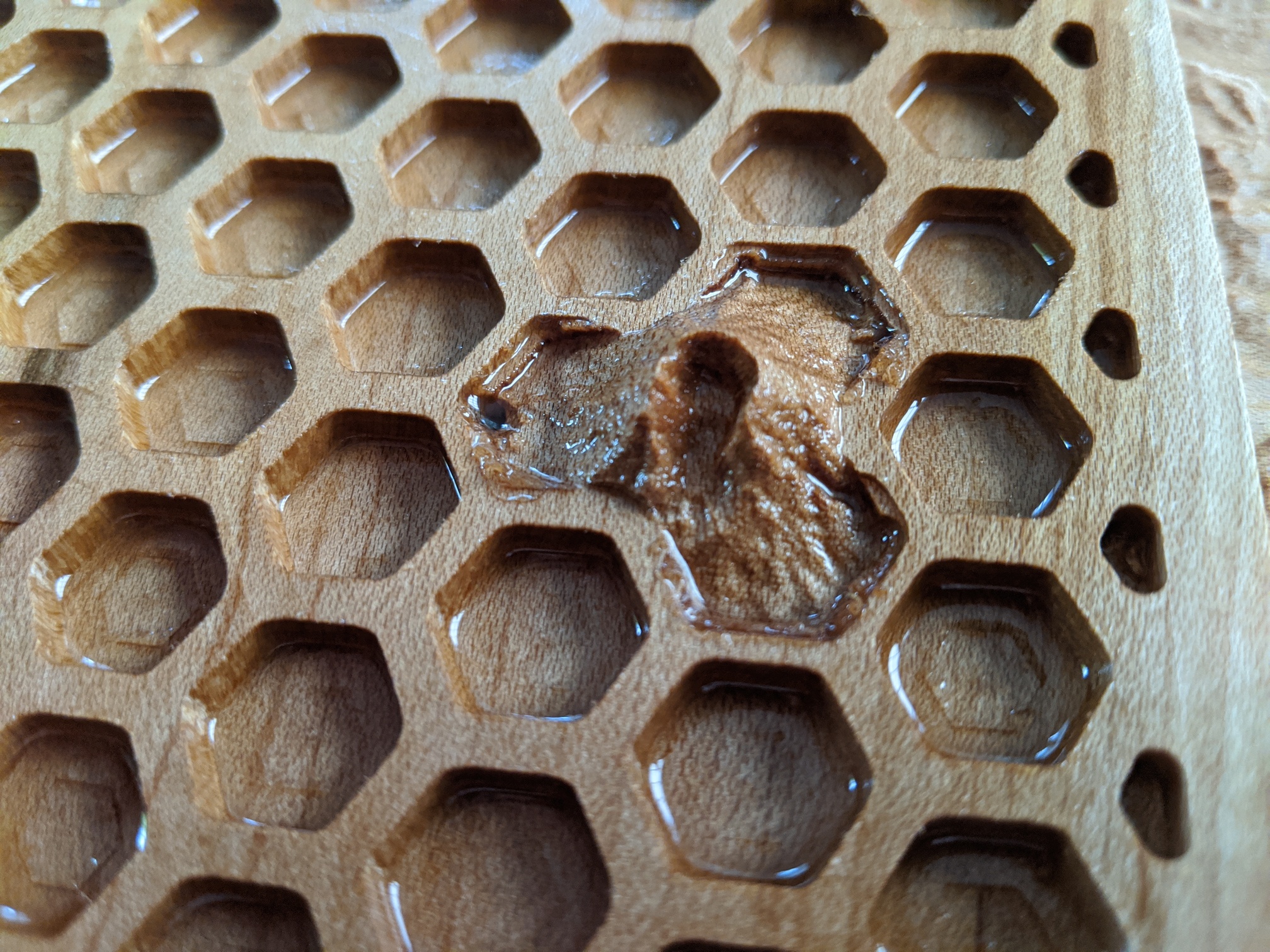
And then @Julien asked in How would you mill this? how to do 3D carving in CCPro with a round design… so obviously I had to have a spontaneous volcano (Mt St Helens) in 3 hexagons:
Now to the digital side:
I used a 1/4" downcut endmill for the major roughing, then a 1/8" inch downcut to make the points in the hexagons relatively sharp (this takes forever) and to do the roughing for the 3D models.
Then I used a 2mm endmill to refine the text, and a 1mm tapered ballnose endmill to do all the 3D carving.
While no animals were harmed in the creation of this, Carbide Create PRO did not fare so well. I’m at 3 bugs at this point (will need to file tickets with support)
The left top and left bottom hexagons are not getting cut out… but they should be (you can see this in the file)
If you delete a layer in the model view with my file, instead of 1, TWO layers get deleted
When doing a 3D roughing pass within a box, the center of the endmill stays in this box, but the radius is not taken into account so the cut veers outside of the box you gave it…
NICE !
(but ssshhh, don’t remind everyone there are secret bonus points for including hexagons and C3D logos)
Oops, I forgot to mention I did encounter that bug (and yes, I cursed out loud). I’ll let you report it then !
We’ll have to debate with @robgrz whether that’s a bug or feature: I was happy it behaved that way when I did my fake submission above, where the toolpath perimeter happened to be the exact size of my stock
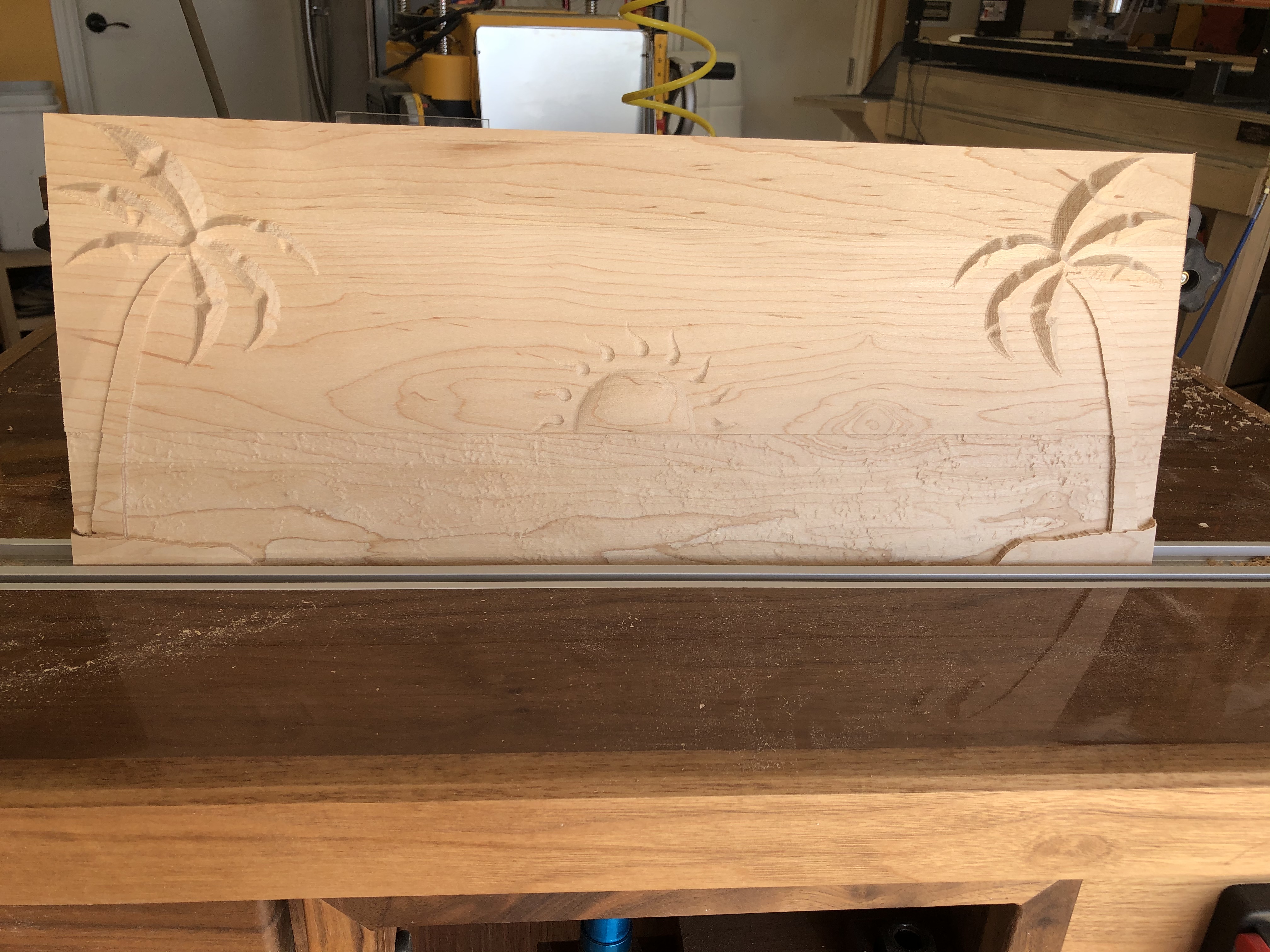
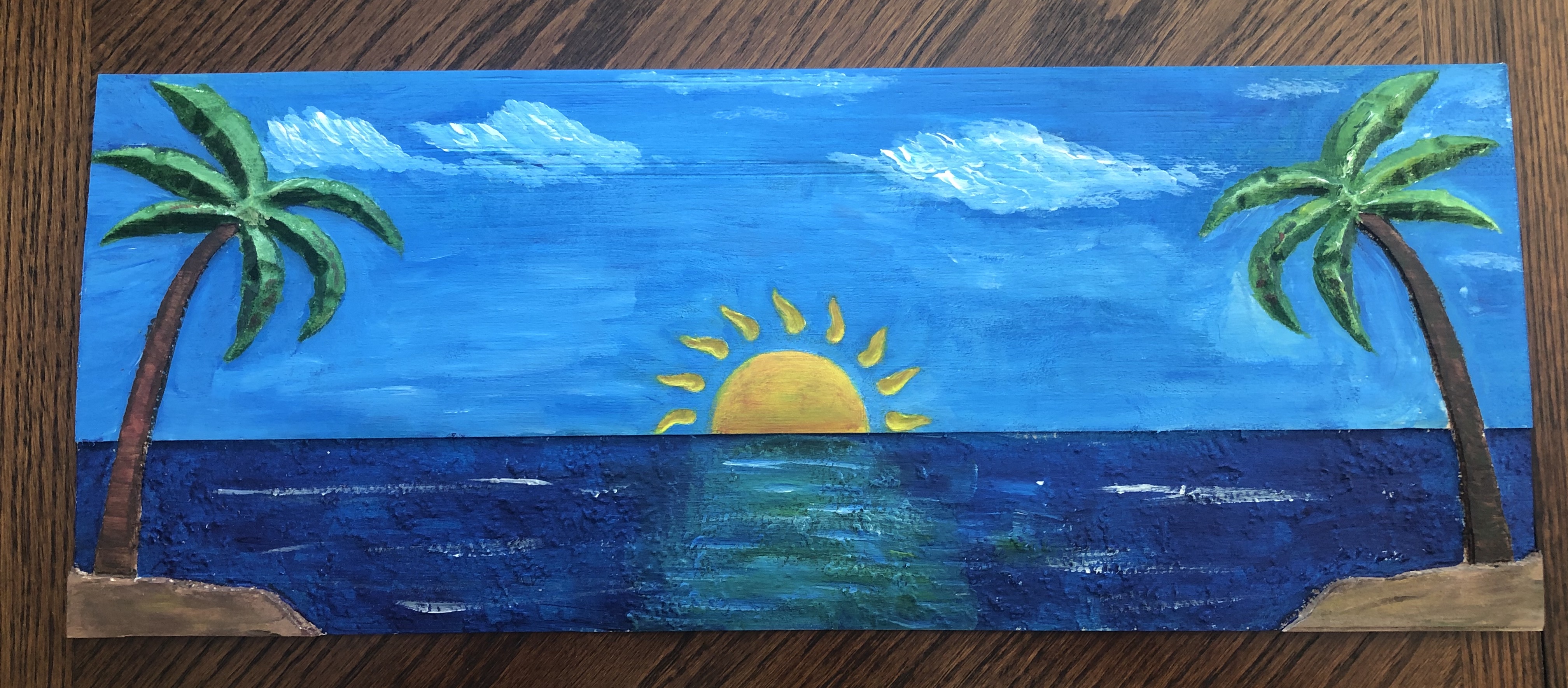
Sharing the below entry. Used pro to create a day at the beach using Pro’s modeling features to take some SVG’s and add depth and the texture feature to add water texture. Carved on 21"x9" maple using .25 rounded EM for clearance pass and milled remainder with .0625 rounded end mill. Wife added some paint for your zen experience and a vote. palm scene .c2d (983.4 KB)