I know you guys are not eligible to win the prizes, but let’s see some entries from:
@robgrz
@edwardrford
@Jorge
@wmoy
@Luke
@WillAdams
And @Julien
Did I miss any?
I know you guys are not eligible to win the prizes, but let’s see some entries from:
@robgrz
@edwardrford
@Jorge
@wmoy
@Luke
@WillAdams
And @Julien
Did I miss any?
So I get confused by the licensed images… so I guess I’m asking is a free image licensed, and by saying no licensed images that means it has to be made by us, meaning no internet pictures or images… am I correct on this thinking I just don’t want to submit something that is not approved
Hi Travis,
You can absolutely use images from the internet if…you are reasonably confident that they don’t have a copyright or some kind of license that restricts their use, and makes them non-shareable. The tricky part sometimes is figuring out whether they do…
In Google images there is a filter for that.
One easy counter-example is the famous Star Wars calendar, or anything else Disney for that matter.
My point was mainly, if you are going to post a file which contains vectors/images you downloaded from somewhere, make a reasonable effort to check that it’s ok to use and share them (both to meet the forum rules, and to keep yourself out of trouble, should be the evil troops of Disney lawyers decide to raid the Shapeoko forum  )
)
Aaaaand…just like that, I’m triggered.
(I blame you for delaying the rest of my todo list items ! )
Awesome thanks for the info. Greatly appreciated.
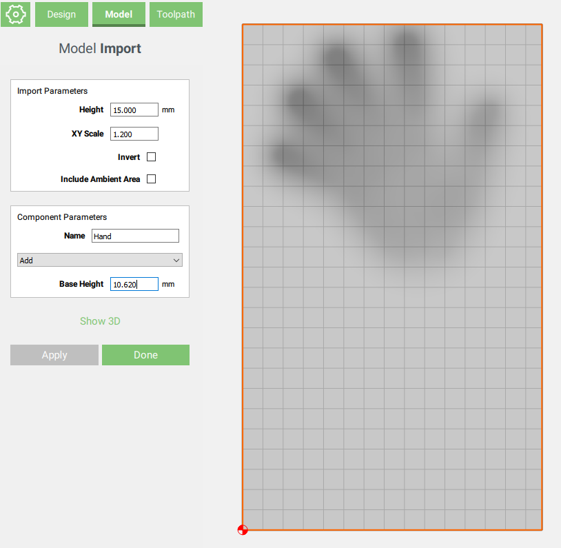
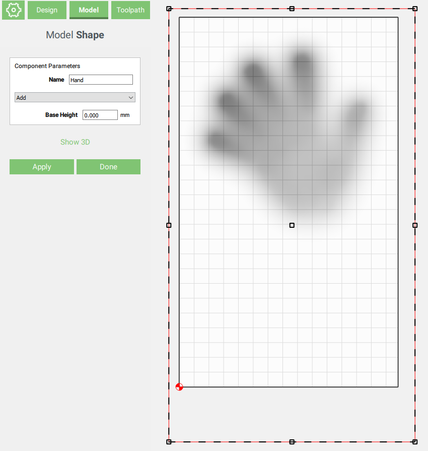
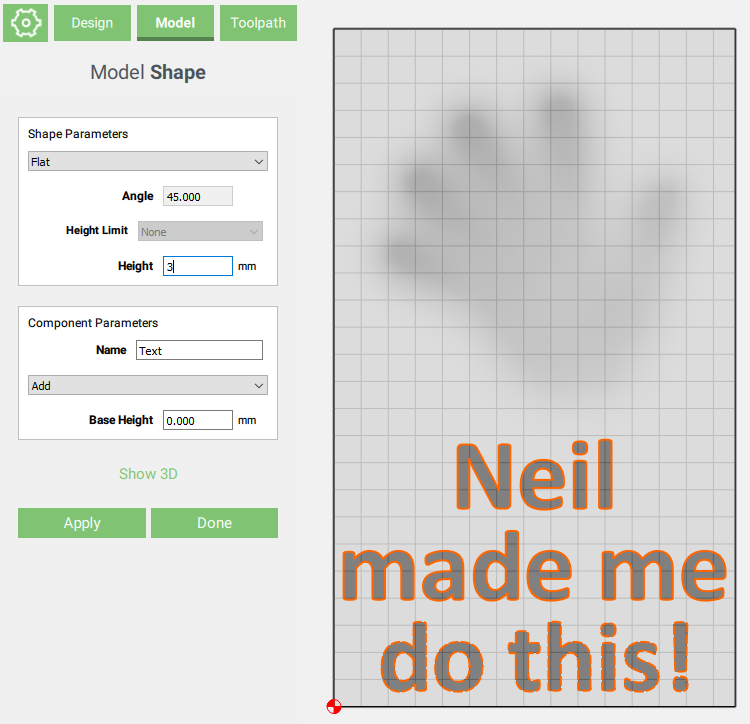
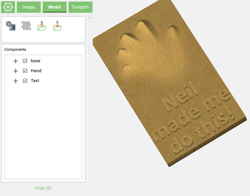
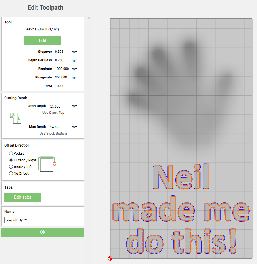
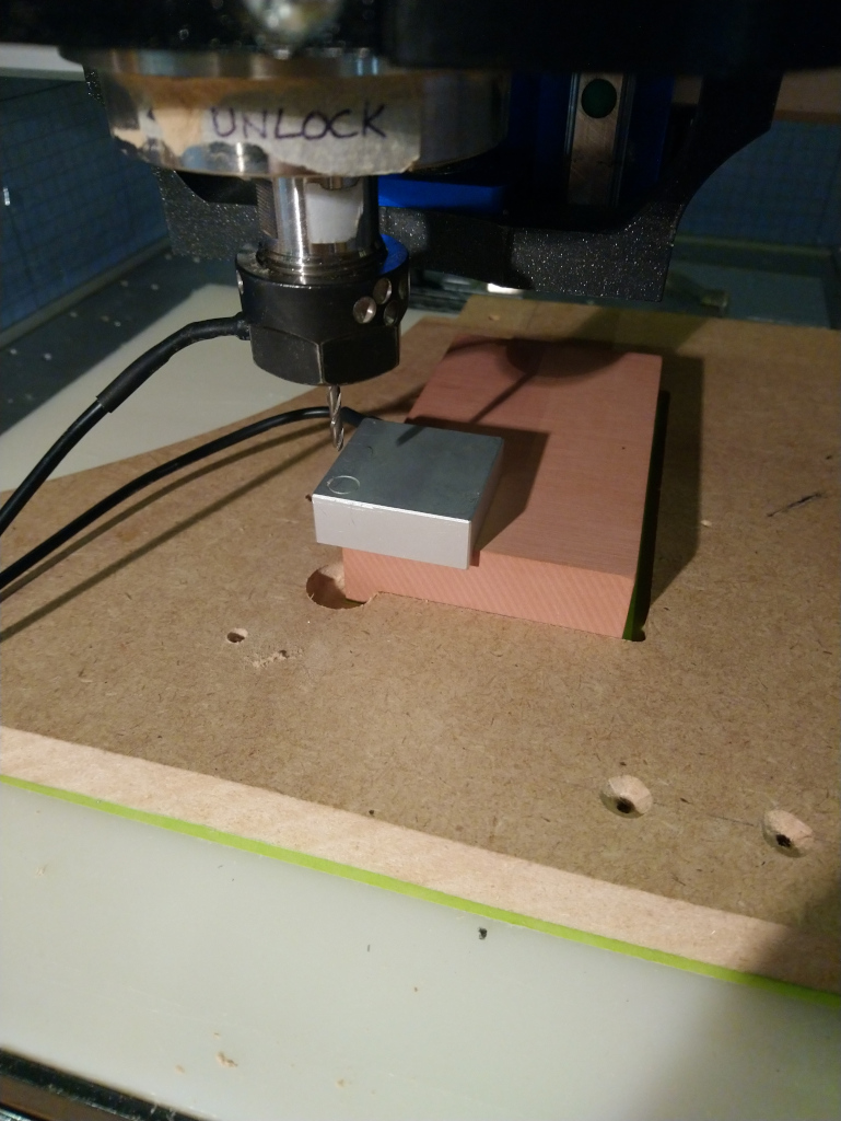
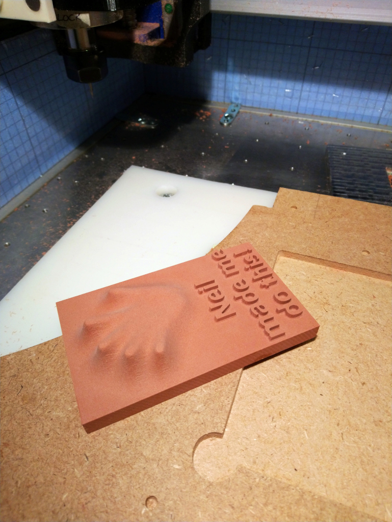
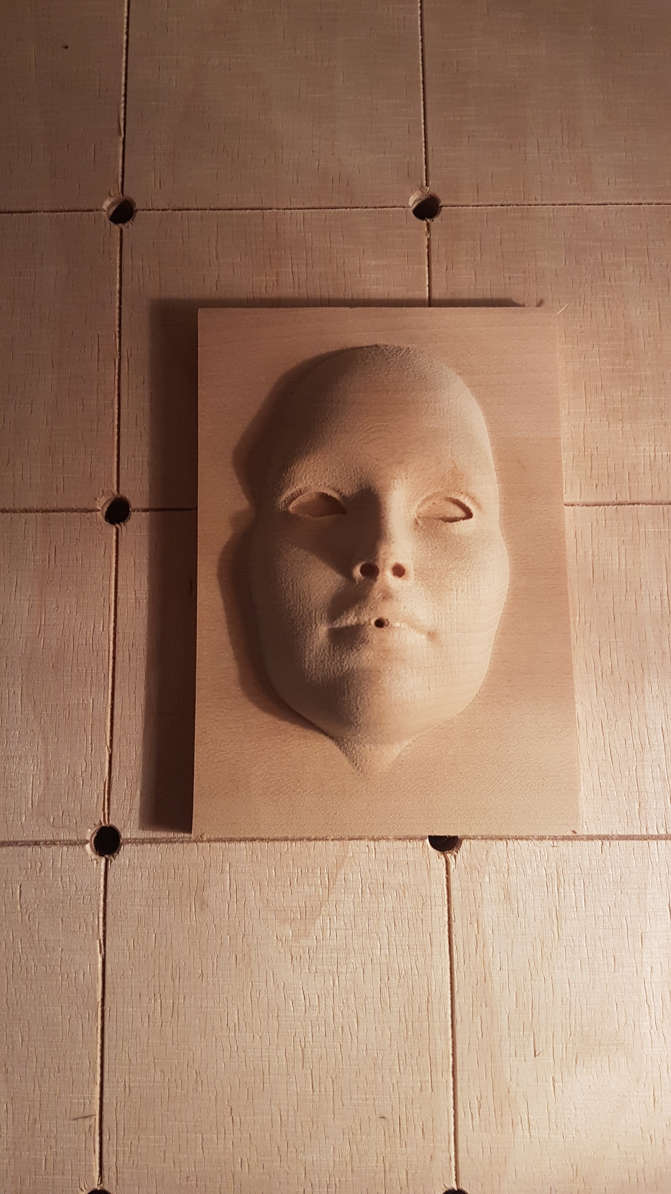
In the spirit of honouring @neilferreri’s dare AND hopefully documenting in the process how easy it is to do a simple CC Pro project, here’s my non-eligible-contribution-slash-CCPro-tutorial:
Ever since the announcement of the Nomad2020, I have had a severe case of Nomad craving, so I figured I would pretend I have one and use my Shapeoko to mill something small and detailed.
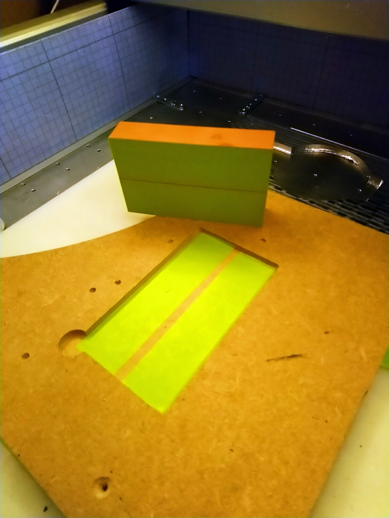
I stumbled upon a block a Renshape that had been collecting dust since I got it in a package from C3D in late 2017, so now was as good a time as any to use it! It’s about 5"x3"x1" (and I measured it to be precisely 73.7mmx124.5mmx25.62mm)
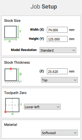
I would not be using Carbide Motion this time (mostly because I have an unsupported probe that I wanted to use for corner probing), and I wanted to have to ability to stop and check things between the toolpath runs, so I decided to save each toolpath to a separate file. I used CNCjs and @neilferreri’s macros to still benefit from the BitSetter for tool changes.
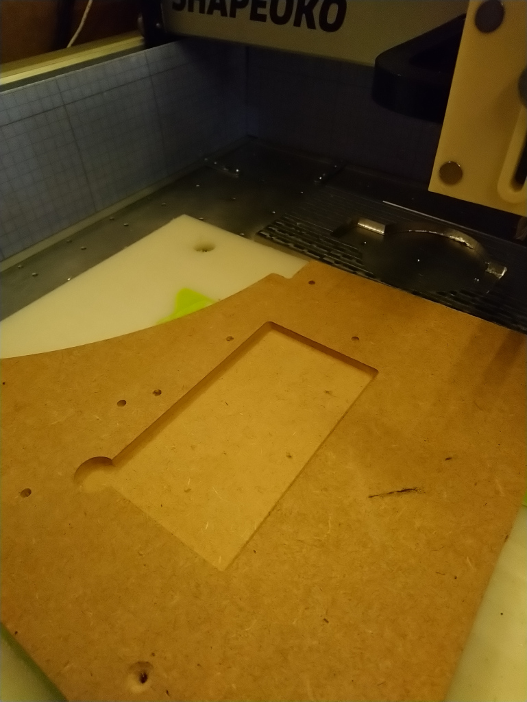
Since I would be milling material from a stock of exactly the size I had setup in CC with no margins anywhere, I decided to cut a jig in MDF for positioning the Renshape stock while being sure that it would align perfectly with horizontal and vertical axes of the machine
side note: I used just a few drops of CA glue for this job, as I did not want to risk breaking the piece of Renshape after the cut when prying it away, and since there would be very little forces on the stock during the cut anyway.
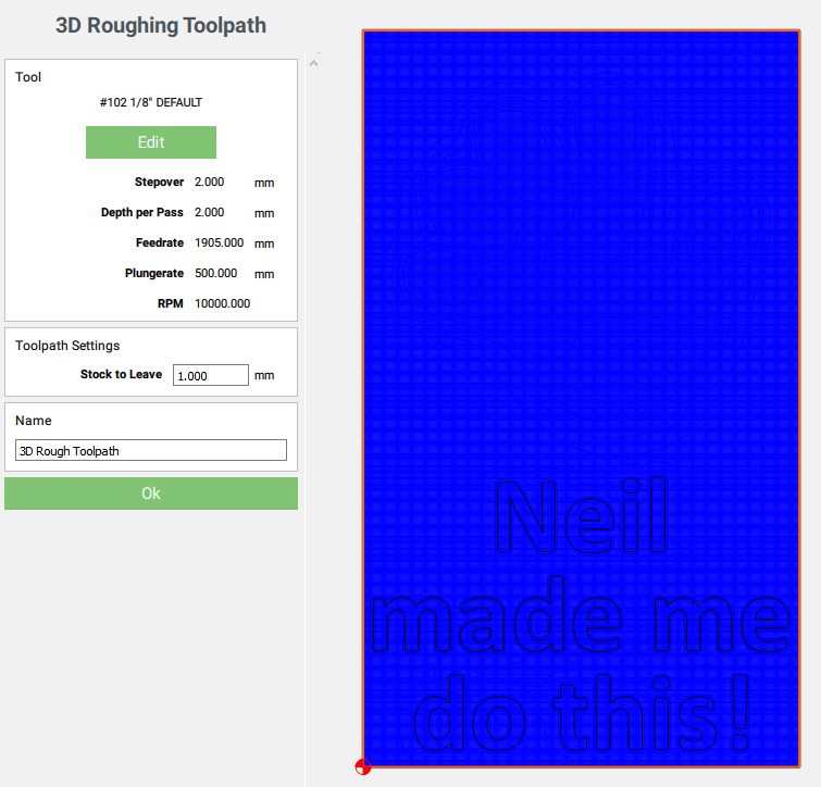
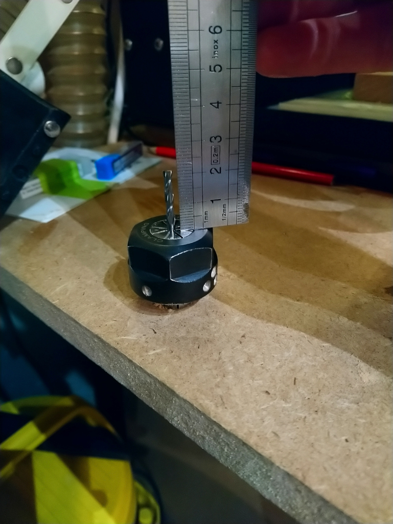
Quick check that my 1/8" endmill was sticking out enough from the collet to be able to mill 15mm of material:
I used my vintage BeaverCNC zero probe and @neilferreri’s touch probe macro to set zeros.
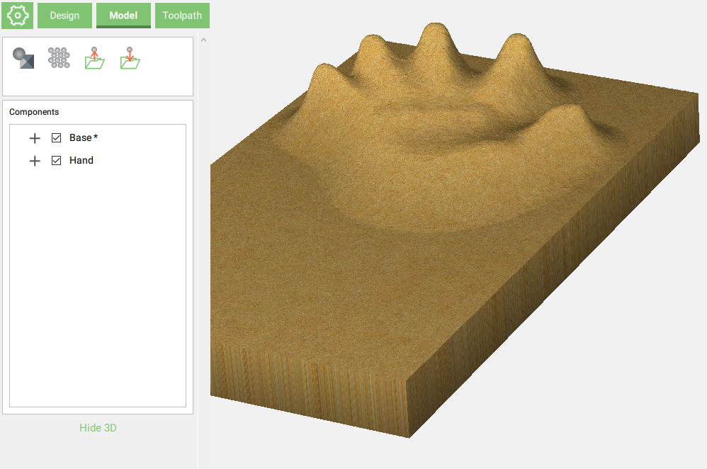
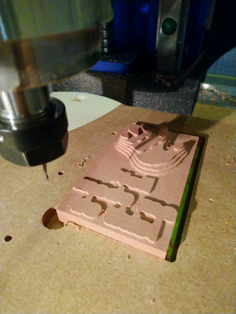
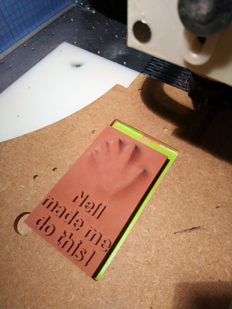
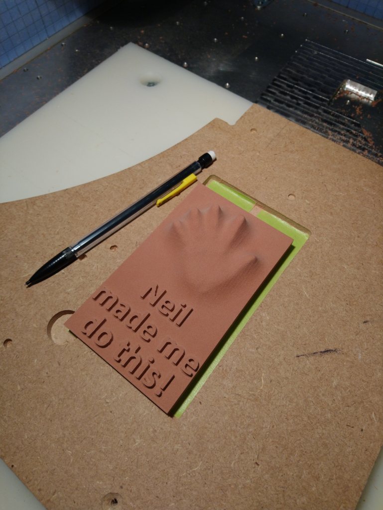
Fininished piece:
There you go. Oh my, Renshape is so easy and satisfying to machine, I have a newfound passion for it. Shapeokos should ship with a few blocks of renshape for beginners I think ! Much more rewarding than everyone’s first cut in pine/fir.
I showed you mine, you show me yours now ! One more week to go to submit something in the challenge.
I thought I’d present you with a little project. I’d be happy to participate… (even if I don’t have all the cutters I need yet;)
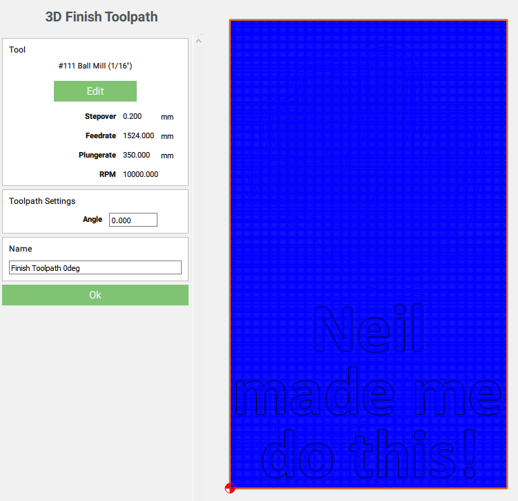
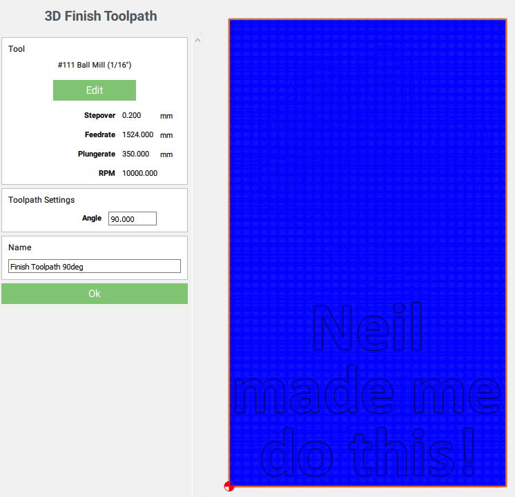
I have had good results even with “flat” cutters, say 2mm… if you have relatively simple geometry even a flat cutter works great… (just do 2 finishing passes, either 90 or 45 degrees offset from eachother)
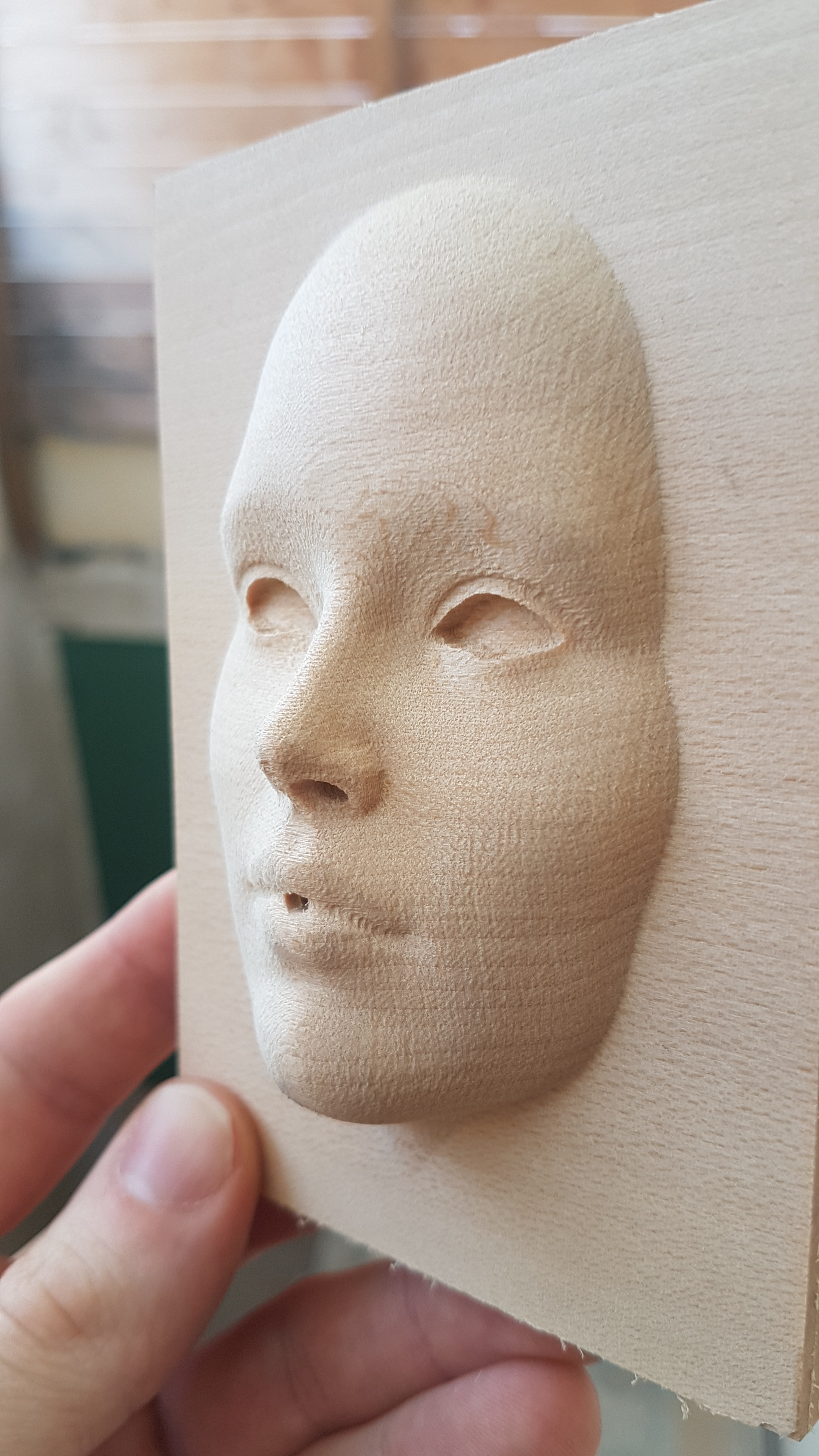
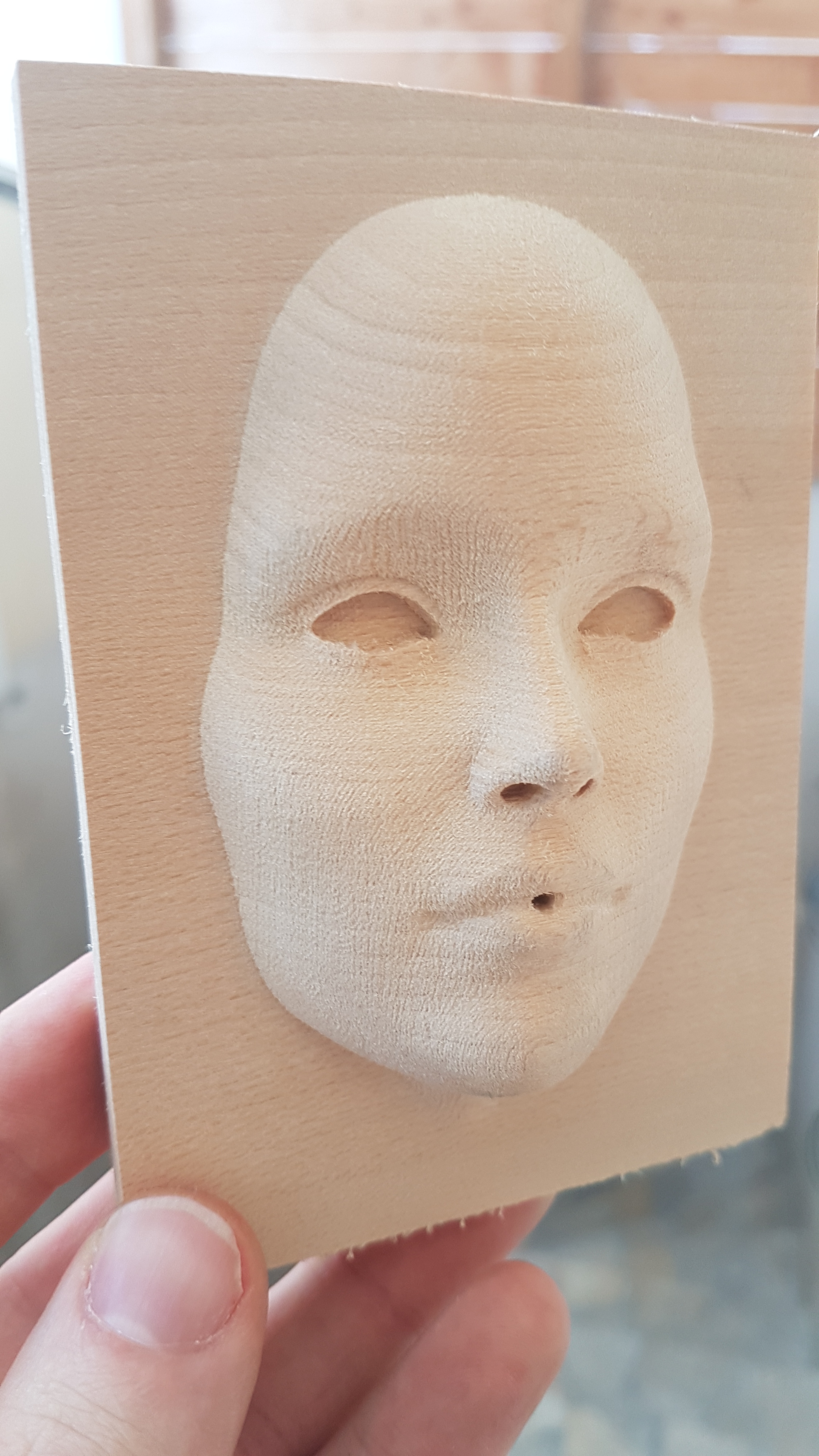
Hello, this is my little 3d project for the challenge.
It allowed me to learn how to use Carbide Create pro for 3d.
And I found it fun. And also to check what Julien says, a Shapeoko can be as accurate as a Nomad 
In two passes, the first on X, the second at a 45° angle.
and the result is superb.
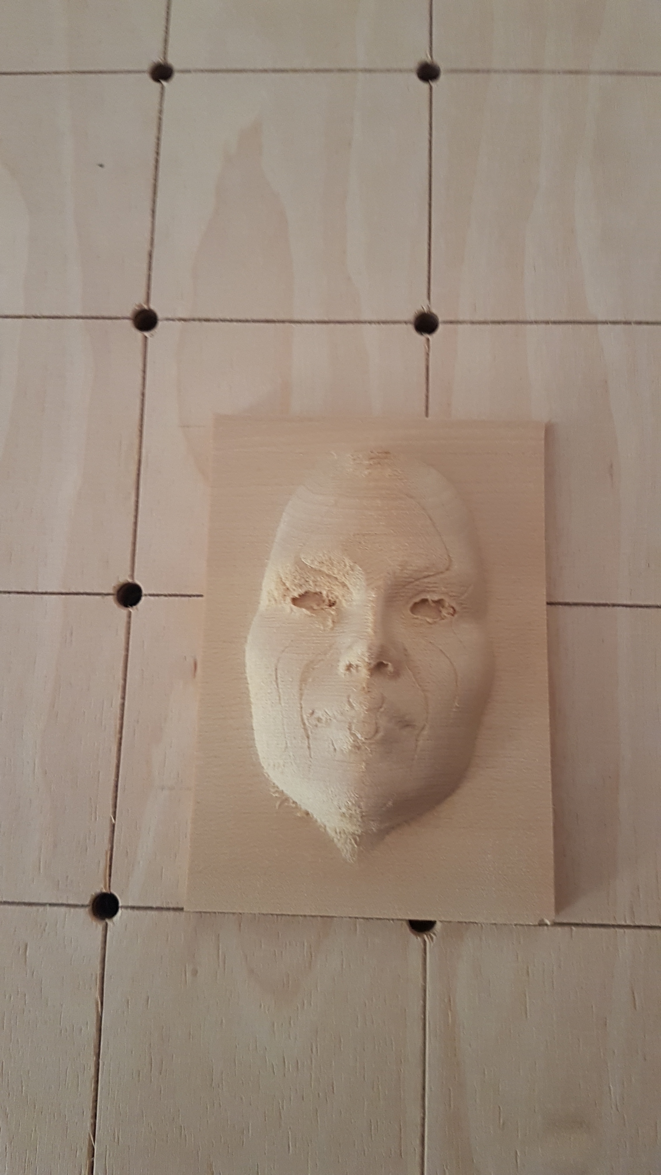
I made a mistake, on CC, I put the reference surface at the top, not easy to point the Z, after the first pass. I played a trick
To memorize for the next times.
face.c2d (90.4 KB)
Thanks for your entry @Bwood34, nice job and greay way to join the community !
Now we just need someone with a Nomad to enter the contest just to prove you wrong on that accuracy statement:
Ok this one took a while to cut (nearly 5 hours).
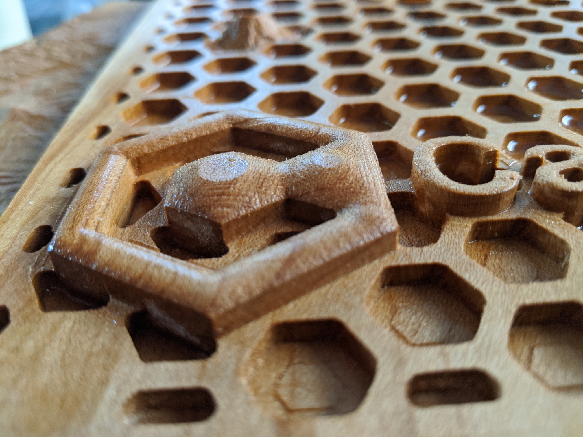
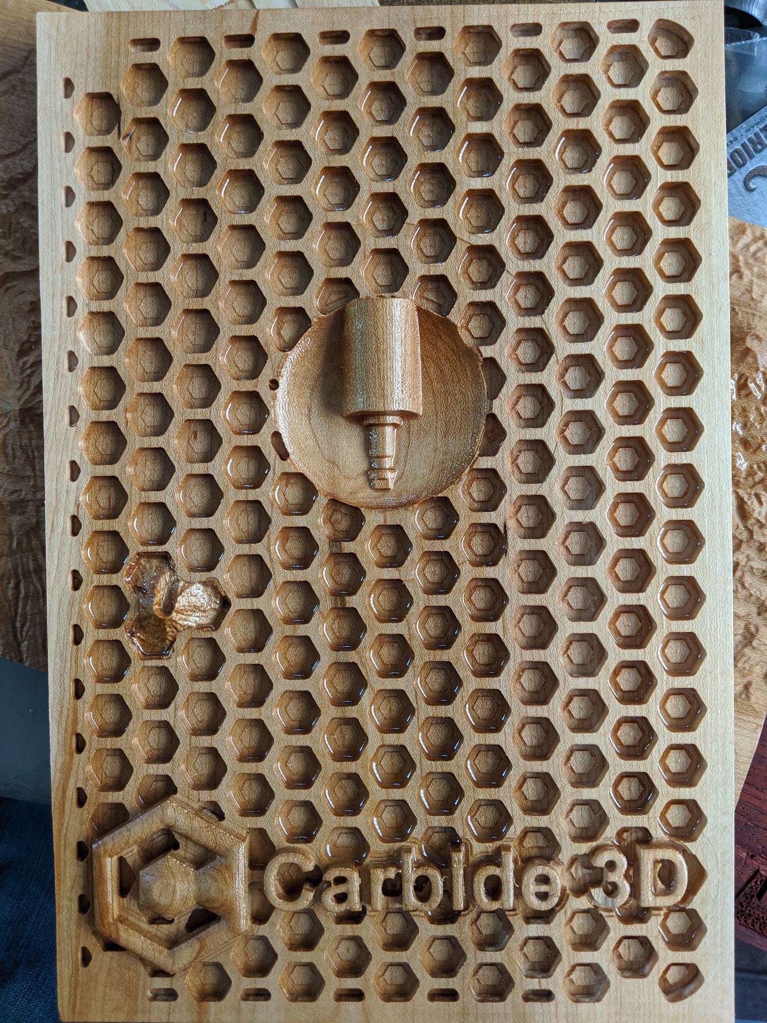
So I looked at the submissions, and noticed a distinct lack of Carbide3D logos in the designs.
Or hexagons.
So I set out to solve that.
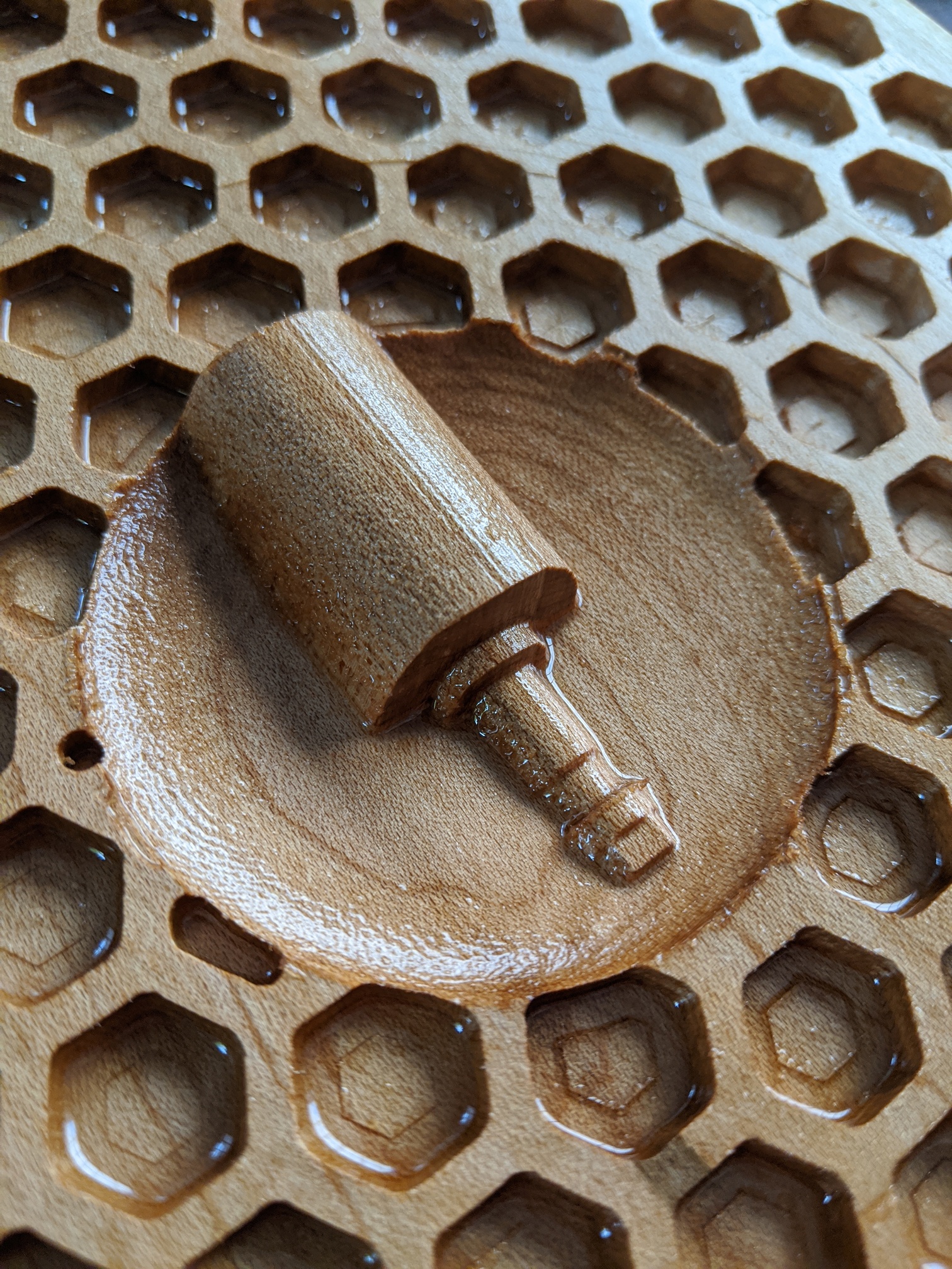
But I also wanted to show the STL2PNG tool I’ve been building…
(https://fenrus75.github.io/FenrusCNCtools/javascript/stl2png.html)
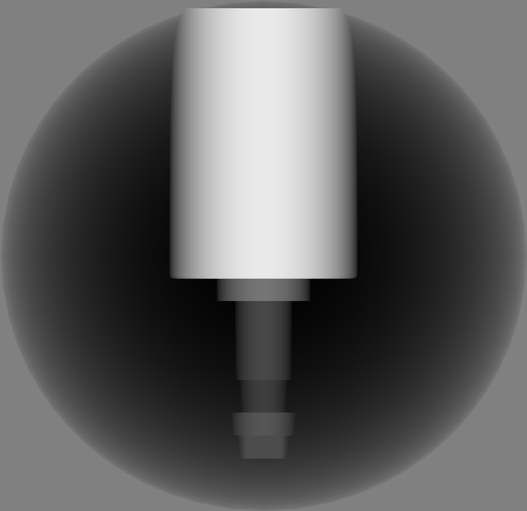
…but I didn’t want to do the traditional horse or eagle in a bowl. Had to be CNC thing…
On thingiverse I found an STL model of a simple spindle: https://www.thingiverse.com/thing:3790264
I had to add 2 features to STL2PNG to be able to use this model, so that took some time, but I’m happy with the result:
And then @Julien asked in How would you mill this? how to do 3D carving in CCPro with a round design… so obviously I had to have a spontaneous volcano (Mt St Helens) in 3 hexagons:
Long cutting time short, the overall came out ok, had some warping issues with the stock near the end:
Now to the digital side:
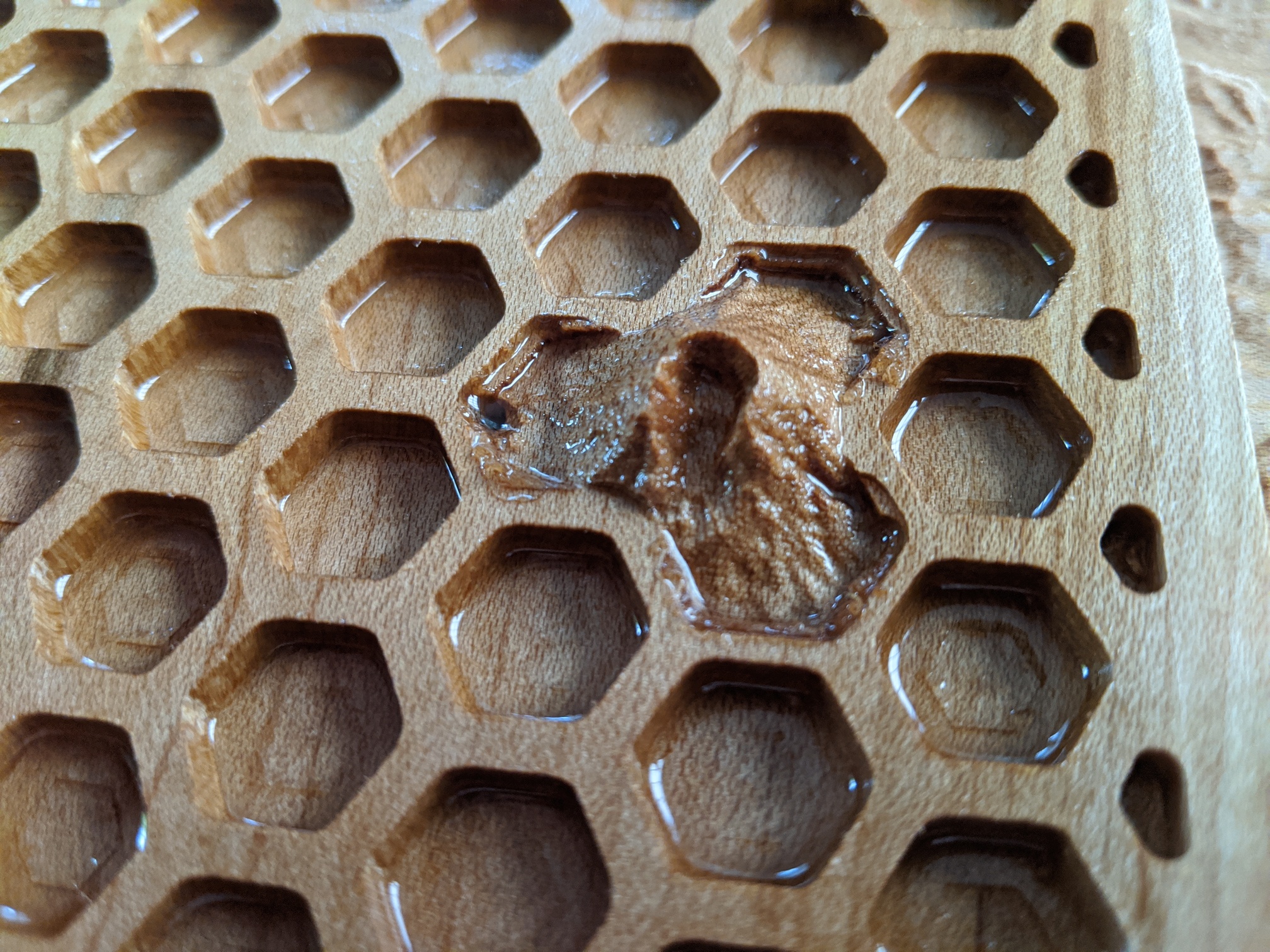
I used a 1/4" downcut endmill for the major roughing, then a 1/8" inch downcut to make the points in the hexagons relatively sharp (this takes forever) and to do the roughing for the 3D models.
Then I used a 2mm endmill to refine the text, and a 1mm tapered ballnose endmill to do all the 3D carving.
While no animals were harmed in the creation of this, Carbide Create PRO did not fare so well. I’m at 3 bugs at this point (will need to file tickets with support)
The files:
hexagonfinal.c2d (1.2 MB)
NICE !
(but ssshhh, don’t remind everyone there are secret bonus points for including hexagons and C3D logos)
Oops, I forgot to mention I did encounter that bug (and yes, I cursed out loud). I’ll let you report it then !
We’ll have to debate with @robgrz whether that’s a bug or feature: I was happy it behaved that way when I did my fake submission above, where the toolpath perimeter happened to be the exact size of my stock ![]()
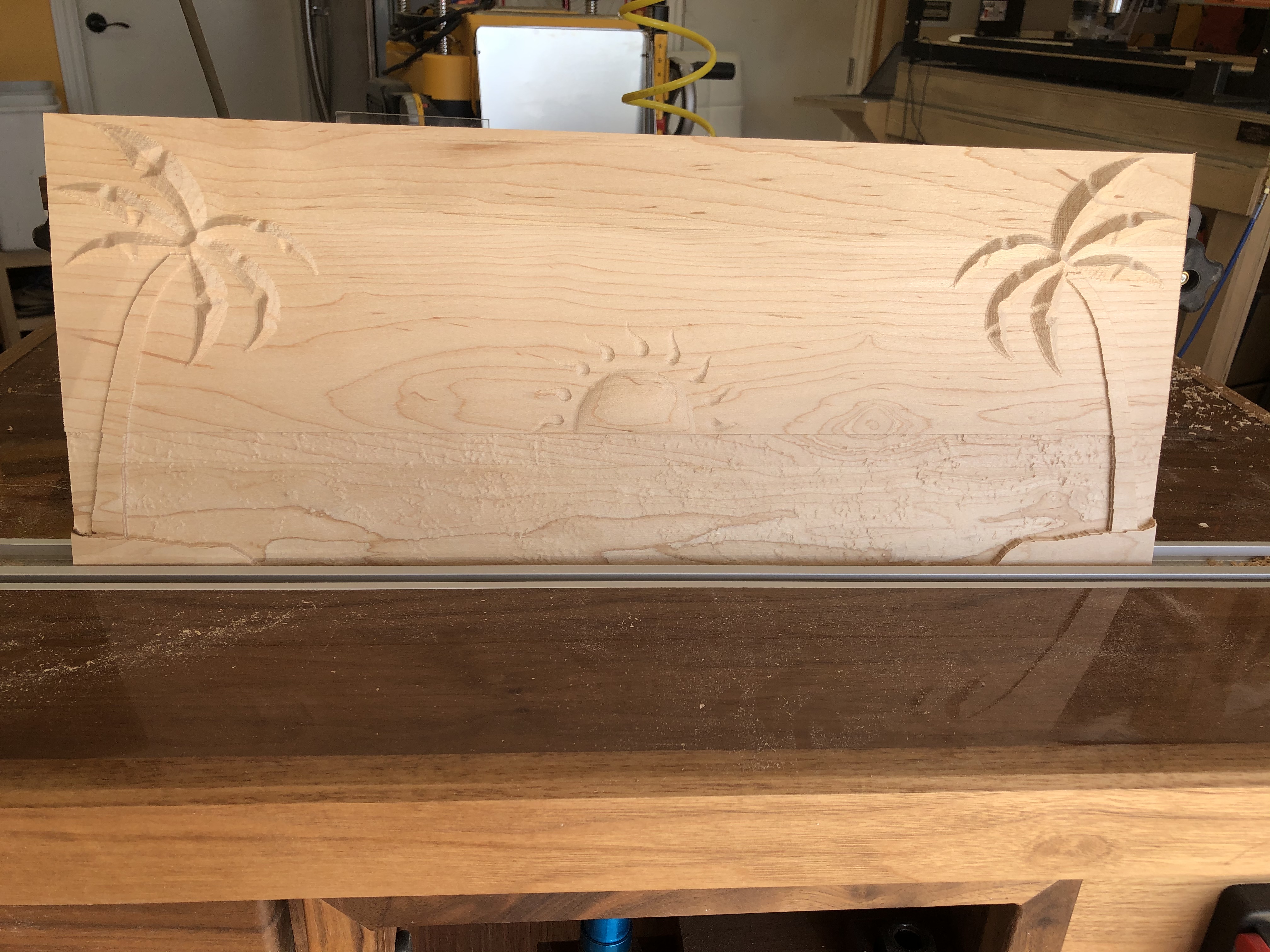
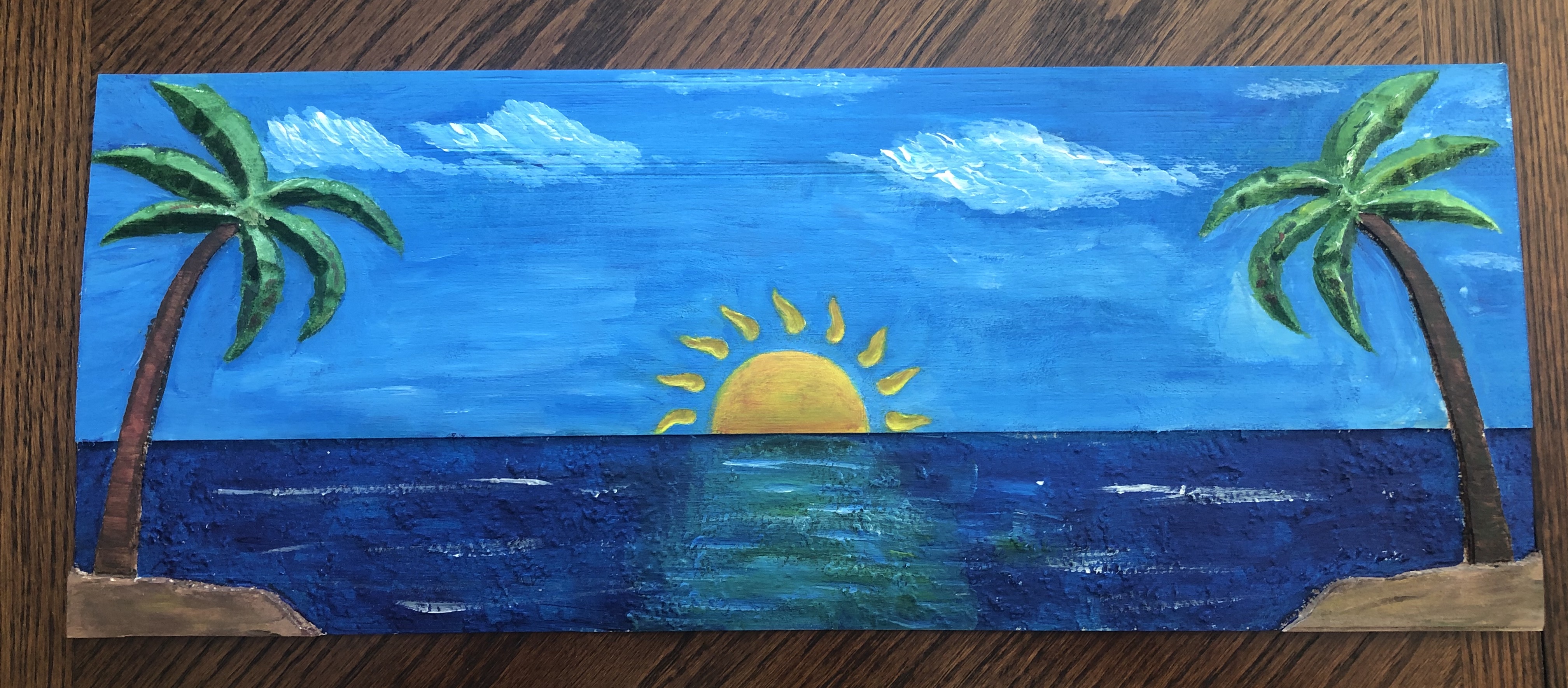
Sharing the below entry. Used pro to create a day at the beach using Pro’s modeling features to take some SVG’s and add depth and the texture feature to add water texture. Carved on 21"x9" maple using .25 rounded EM for clearance pass and milled remainder with .0625 rounded end mill. Wife added some paint for your zen experience and a vote. 
 palm scene .c2d (983.4 KB)
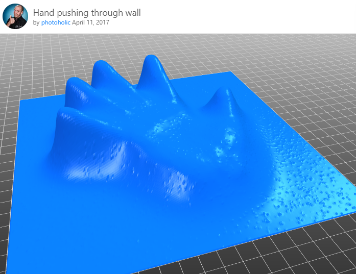
So I did the New Zealand thing, sort of. Going to look more into doing the light diffusing for the acrylic thing eventually.
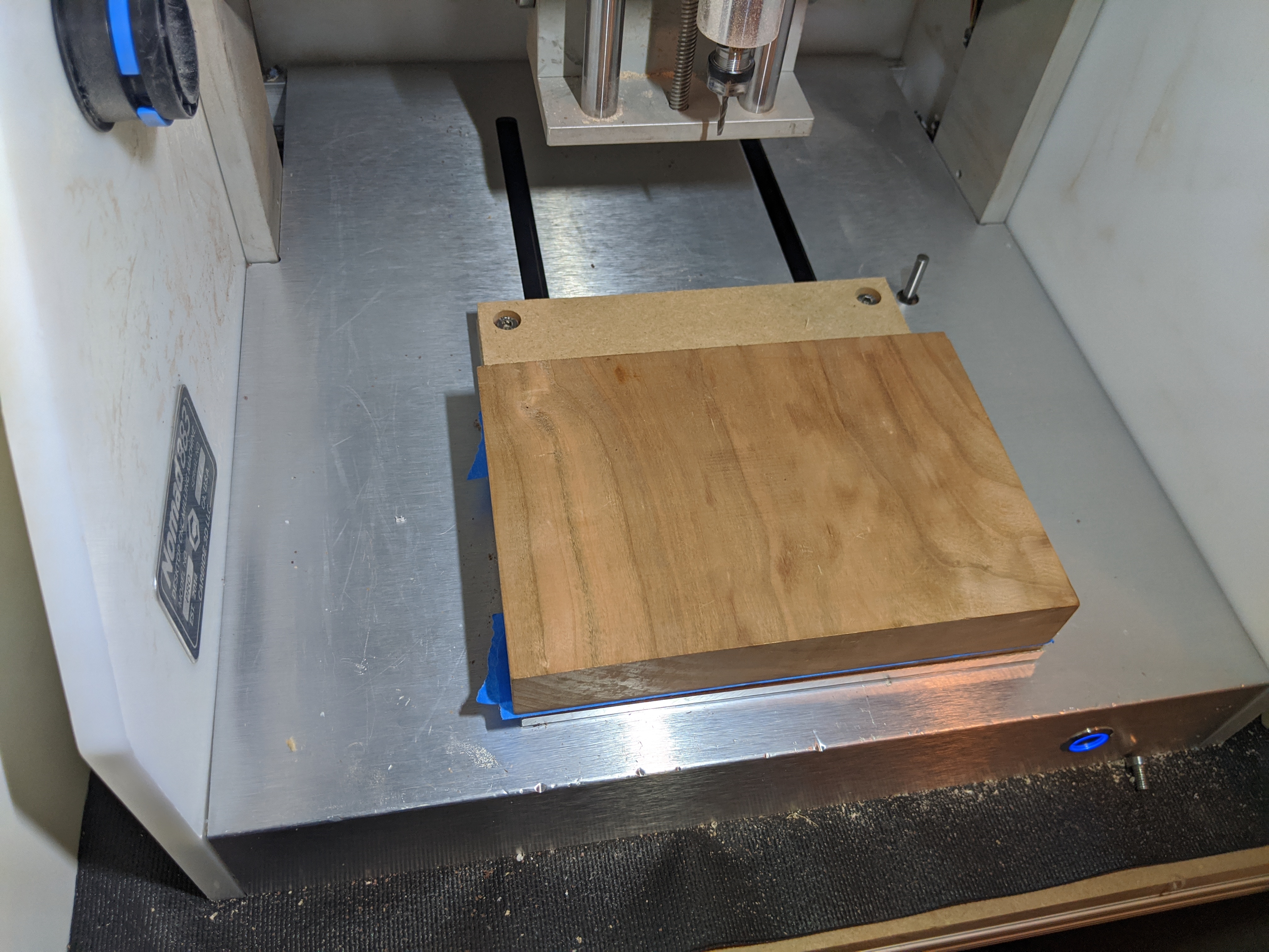
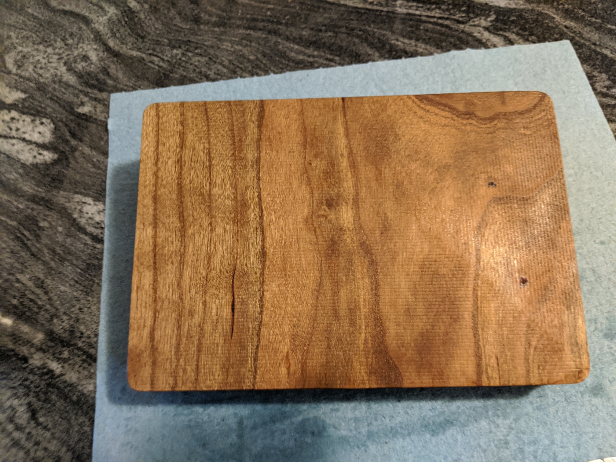
I had a piece of cherry that was sizeable enough to not throw out that I pulled for this. Figured I’d make a catch/valet tray for a buddy who let me stay at his place a while ago. He lives in the States but is from New Zealand.
Stock size determined the tray size. I made a box that was 190mmx130mm and then a fillet with a 7.5mm radius. The rounded over edge ended up complicating things down the road, but still worked out okay. Made a second box that was 15mm smaller for the start of the inside of the tray. 3rd and 4th boxes inside are to help round over the corner from wall to floor. I selected the 2nd and fourth line and did a subtraction operation to make a rounded channel, then selected third line and flattened the floor to the floor height. Imported the NZ height map and did an add operation to raise it slightly above the floor height. Because the island is so big the terrain details aren’t very well defined. I had to do I think a 1.5mm top height for it to not look super goofy.
I can do a more detailed post on design work if people think that would be helpful with screenshots of each step. Wasn’t too hard, but did take a bit of trial and error that I’d be happy to help people not have to go through.
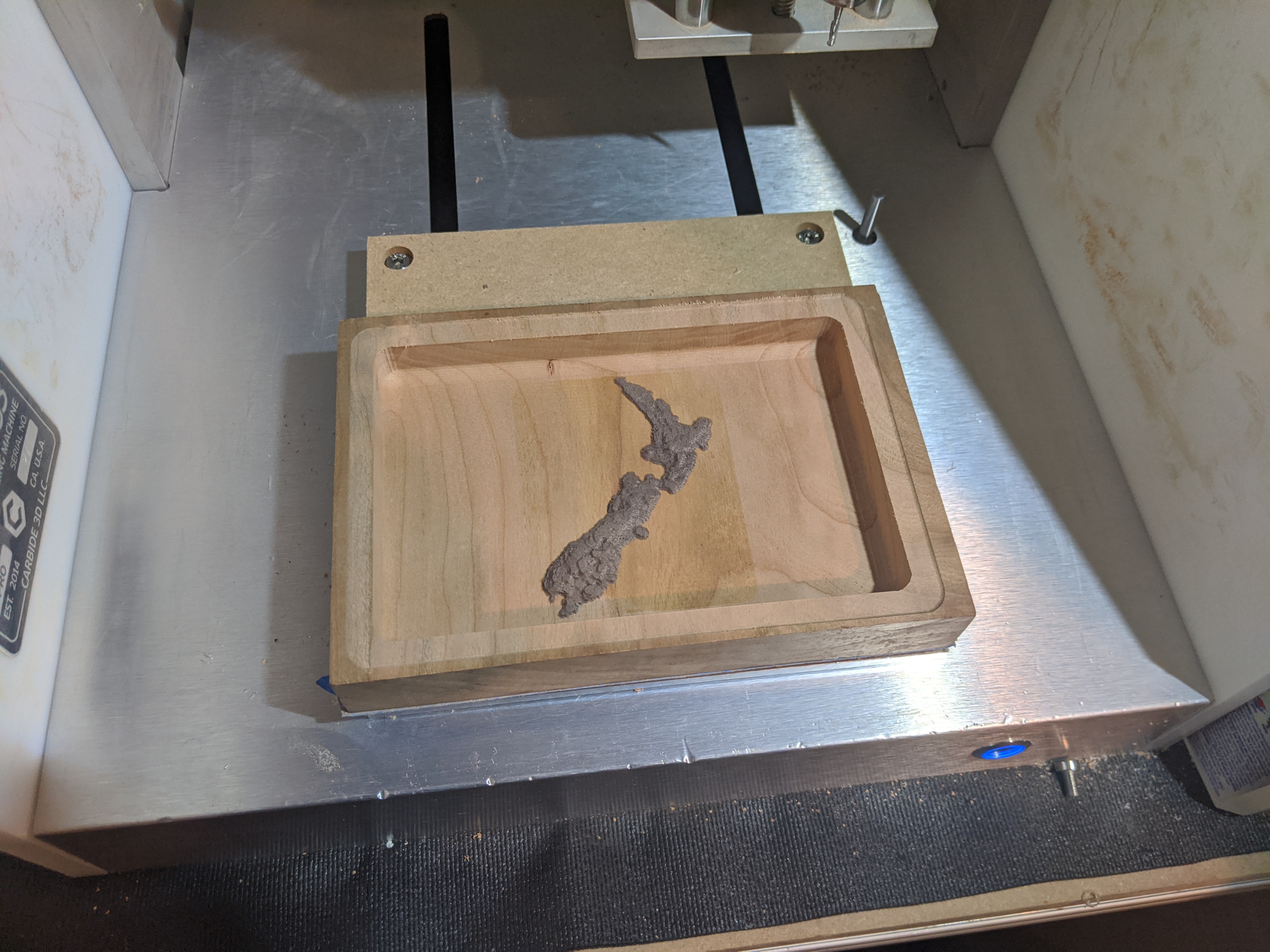
Machining process:
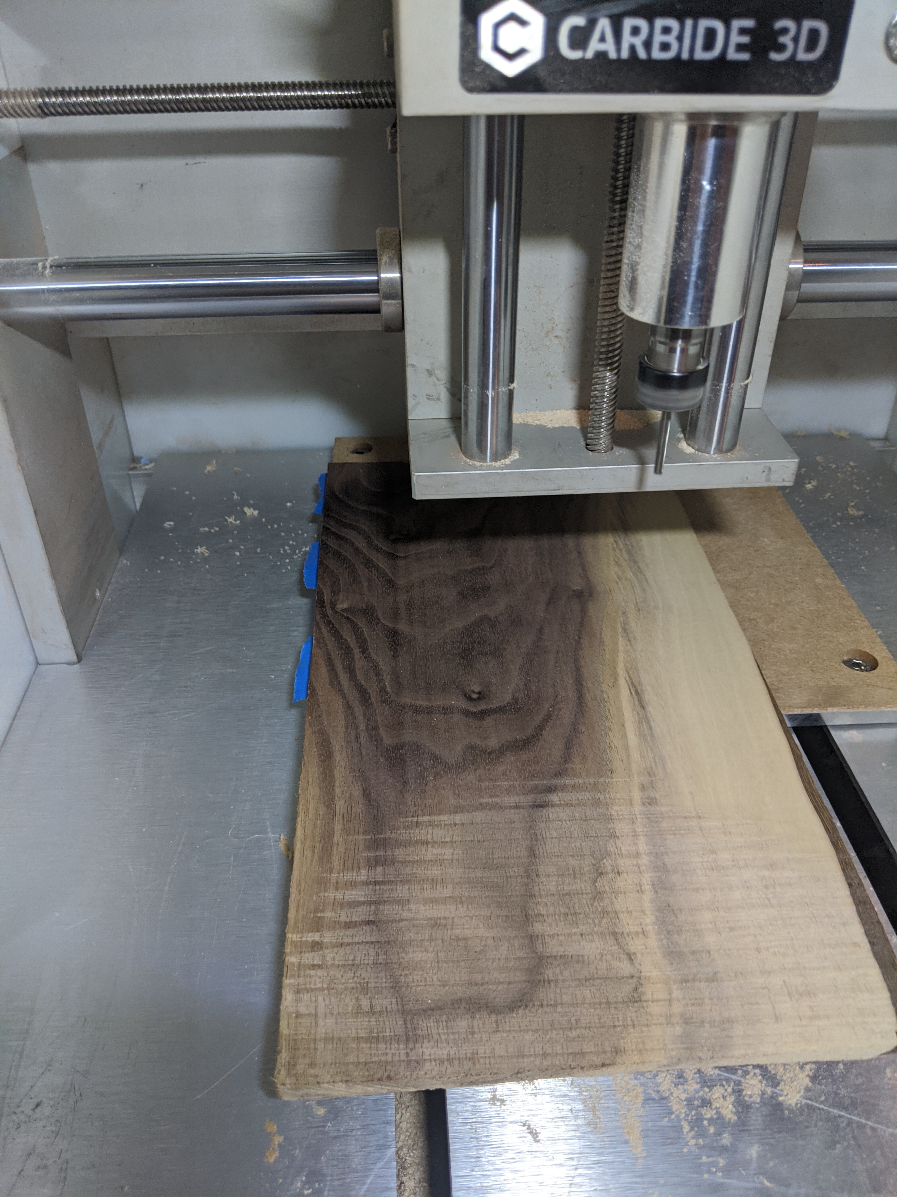
Cut out the insert for the island (in this case a thin piece of walnut) and also flattened a face:
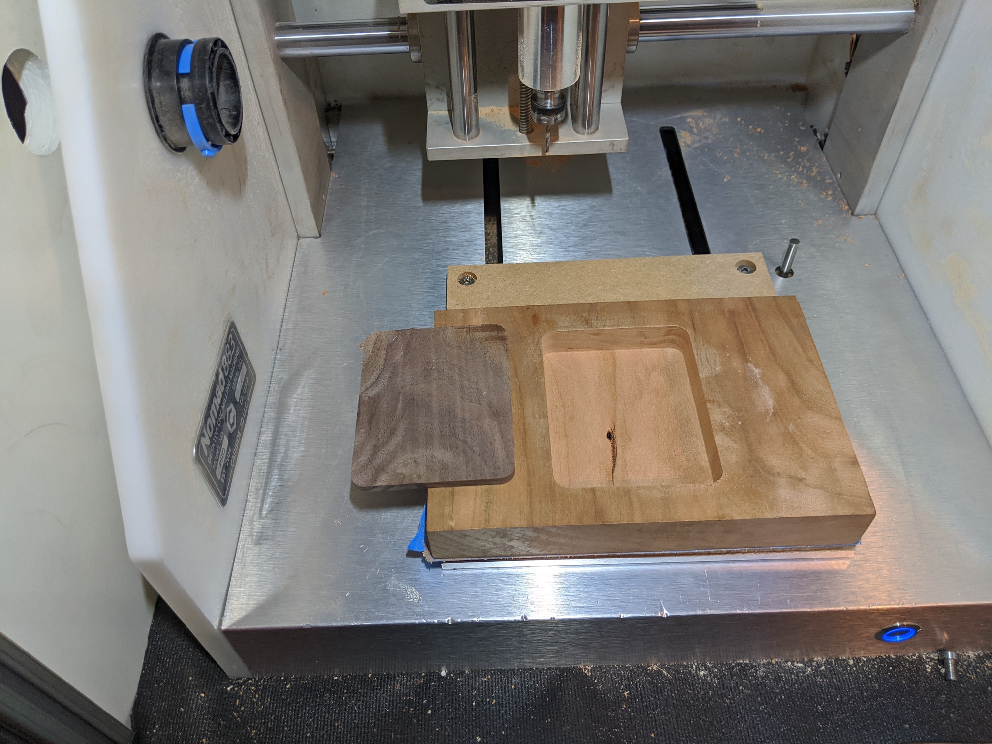
Then I pocketed out a hole that was slightly larger in the walnut that corresponded to where the island would be.
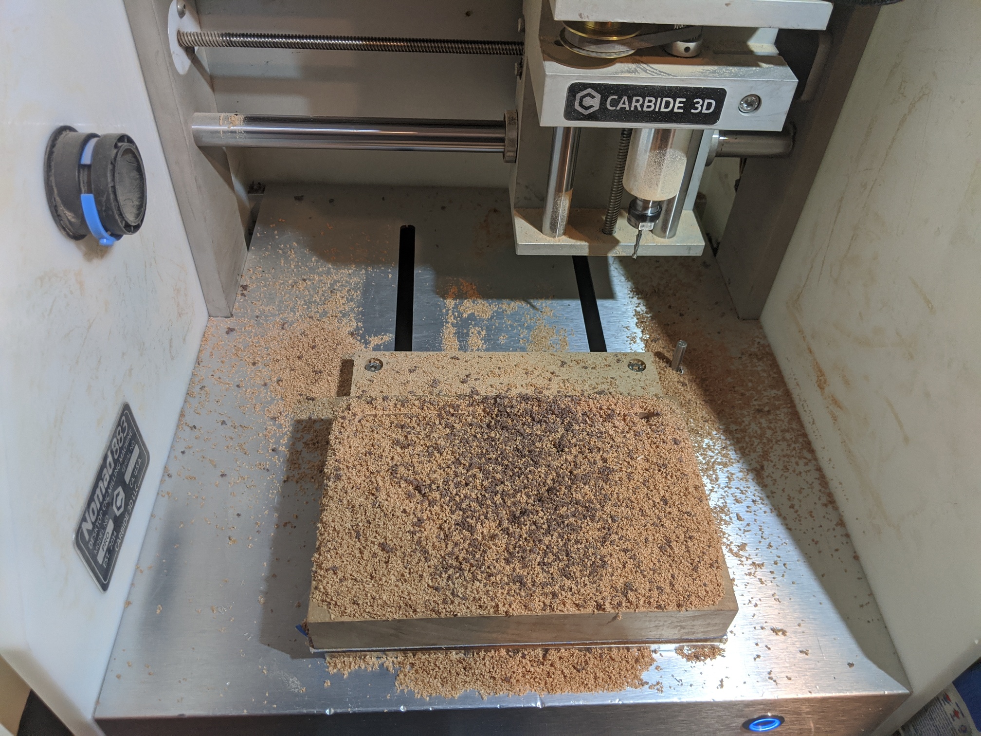
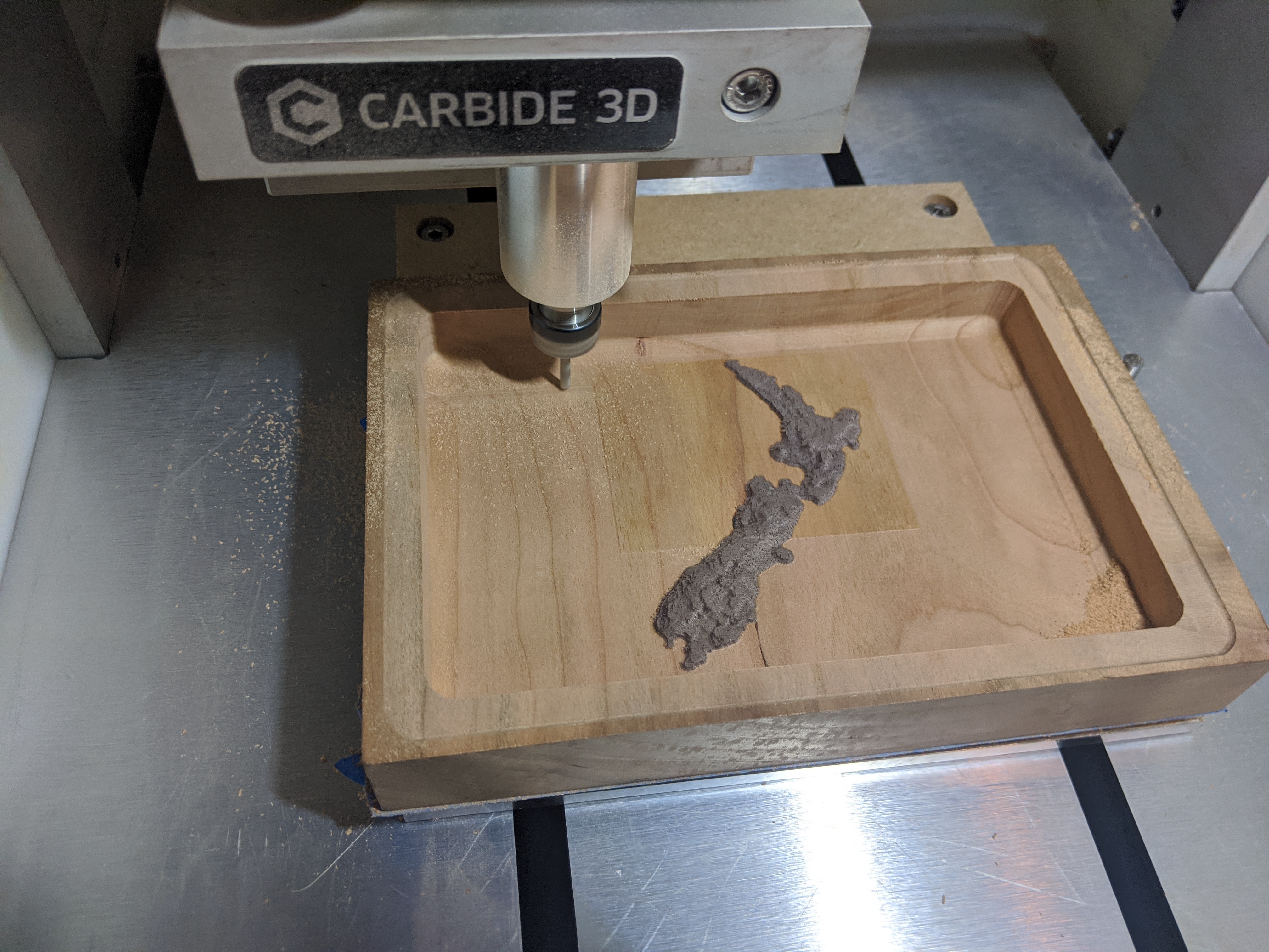
Glued the parts together and then I did a 3d roughing pass (which took forever):
There is a slight discoloration of the wood from the glue, so I dropped my z height by .125mm and ran another pass:
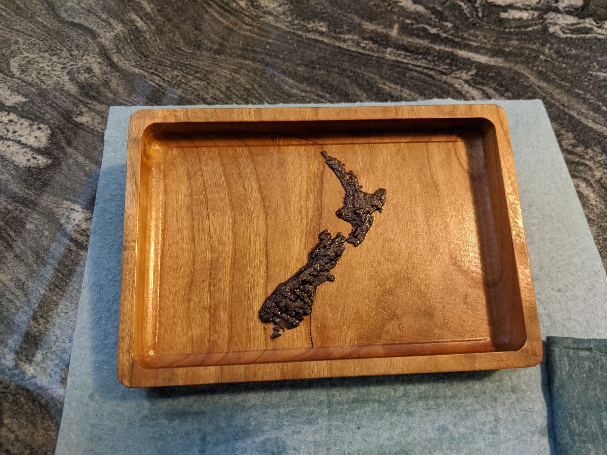
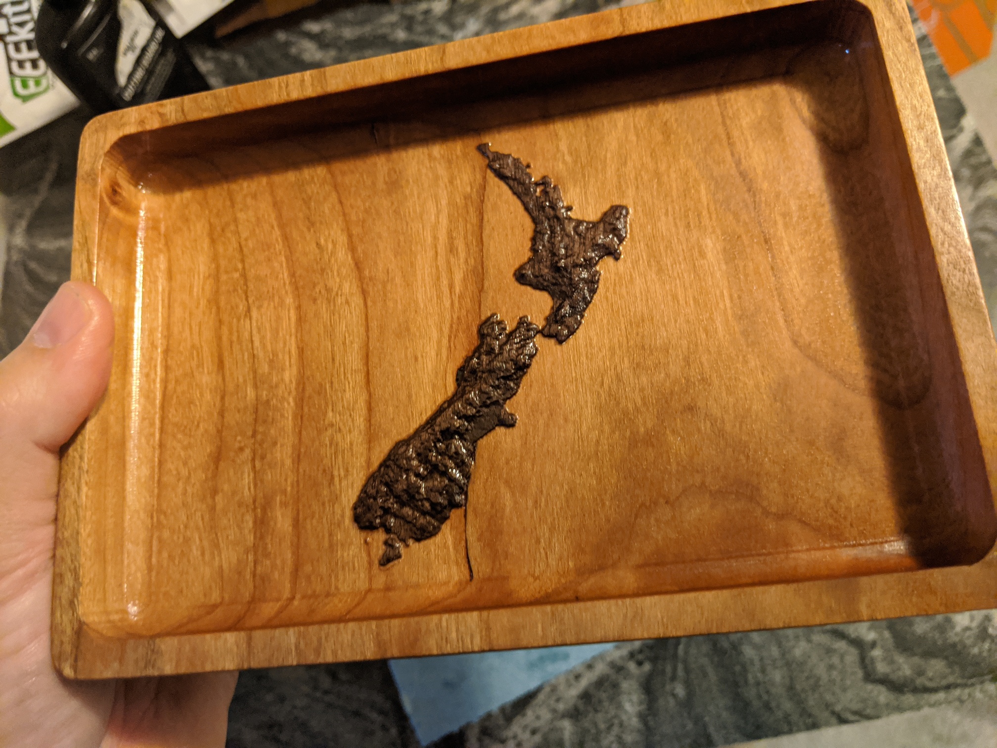
Then cut the box out and did some light sanding to round over the edges. Then put some oil on it and was pretty happy with the project.
A buddy suggested making trays with raised initials for people, which I think I might make a few of.
![]()
Maybe I should go for a 3rd entry…
File:
NZ catch tray.c2d (231.8 KB)
That will make for a happy kiwi !
It’s great to see some Nomad entries in this challenge (did I mention I have a case of Nomad-lust these days?)
I started learning to use Carbide Create on March 15th, which for me was day one of “social distancing”. Carbide Create is the first CAD software I’ve used, before this my kid did the CAD work and I focused on knowing how to operate the Nomad 883. The kid is off at college, so I lost my (free) CAD designer which is why I am just now learning that side, but we have owned the Nomad since Christmas of 2014.
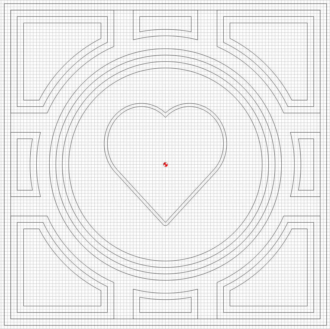
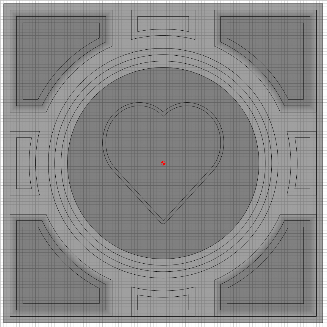
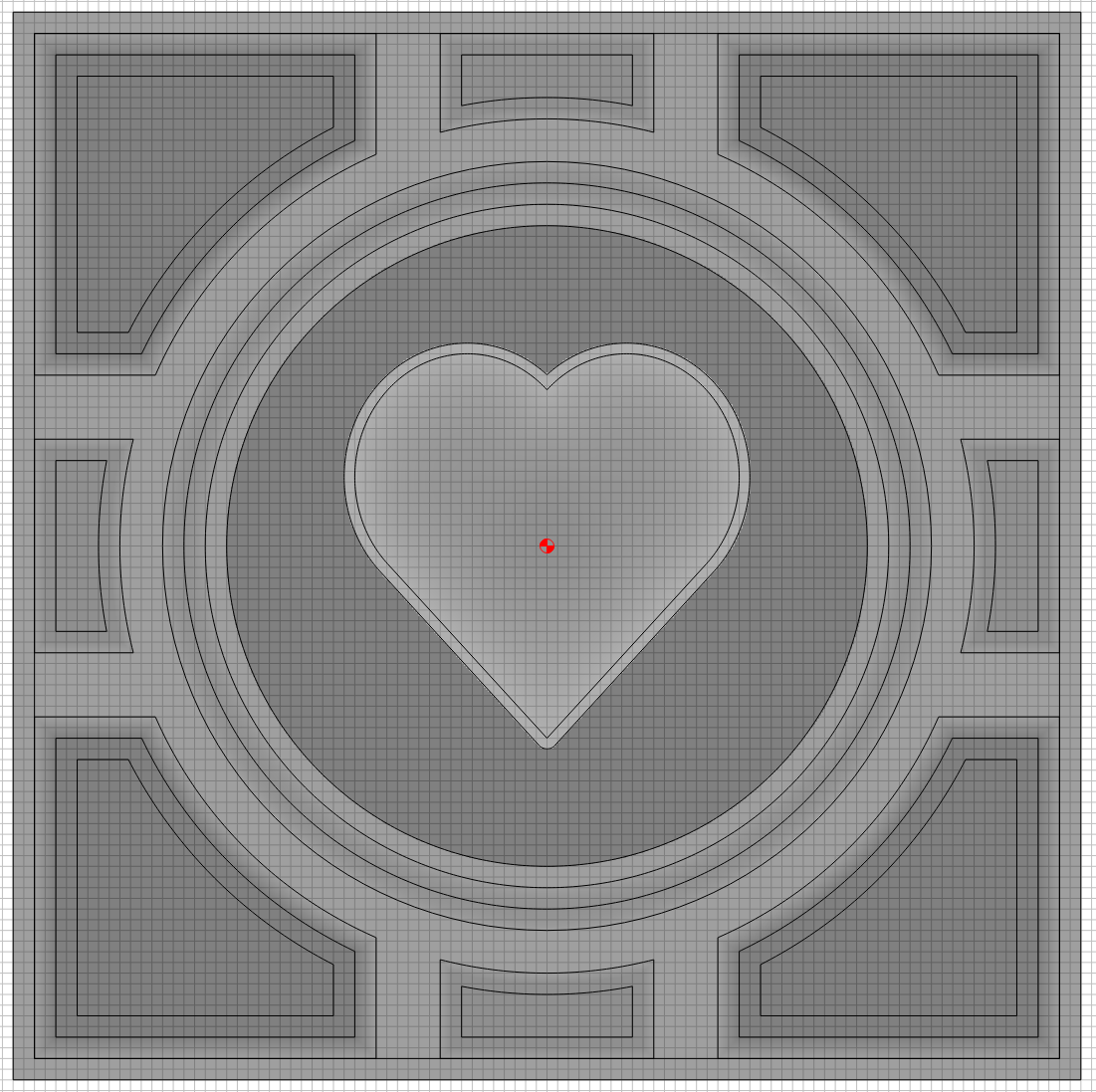
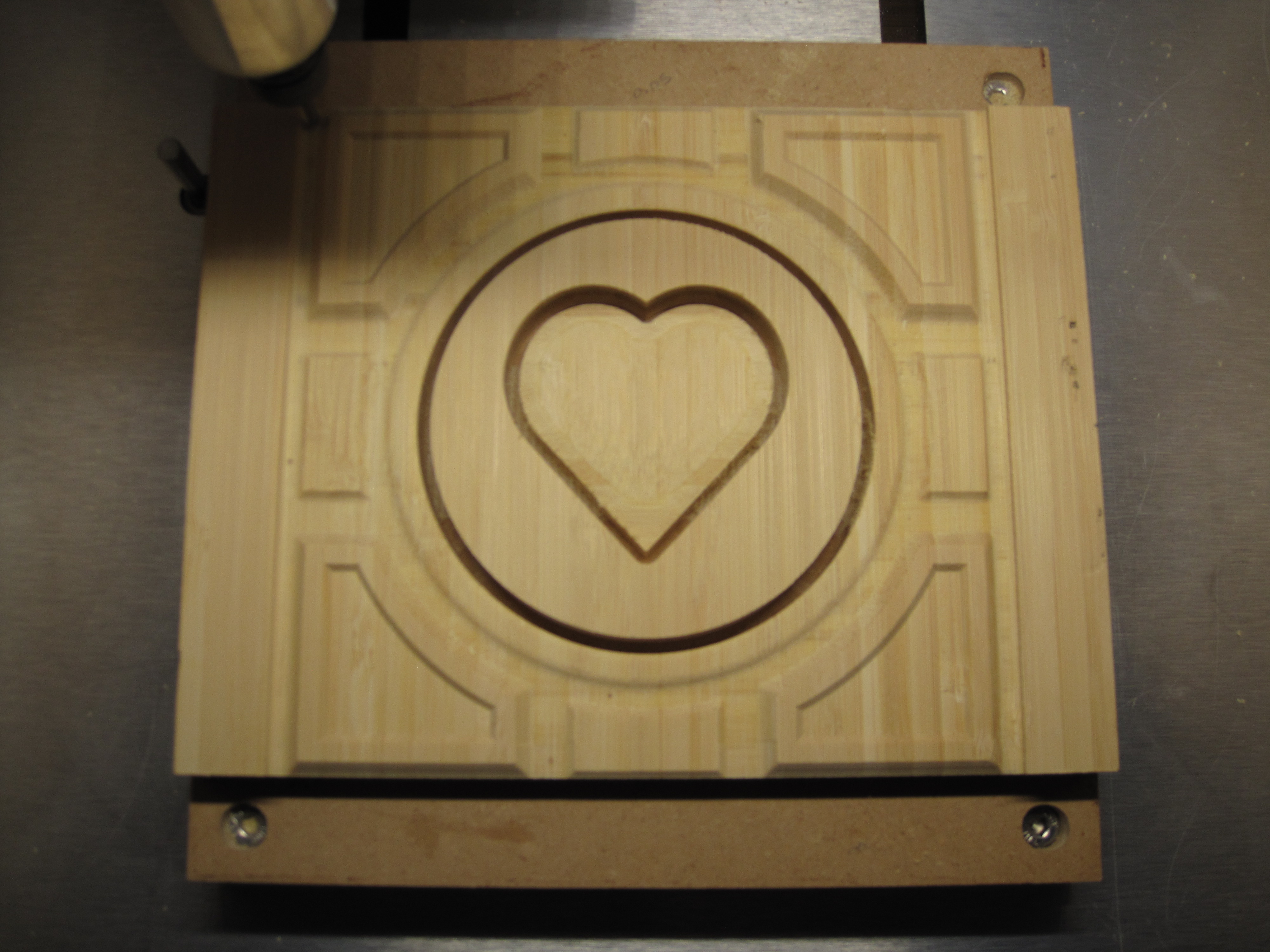
Two days ago I started learning how to use the Pro 3D modeling features in Carbide Create, what you are about to see is the result of my efforts , yes this is my first “pro” design so be gentle. Nothing was imported, everything was created within Carbide Create using simple objects and the built in 3D modeling. The design is from one of my kid’s favorite computer games, what you are looking at is one side of what will eventually be a six sided cube.
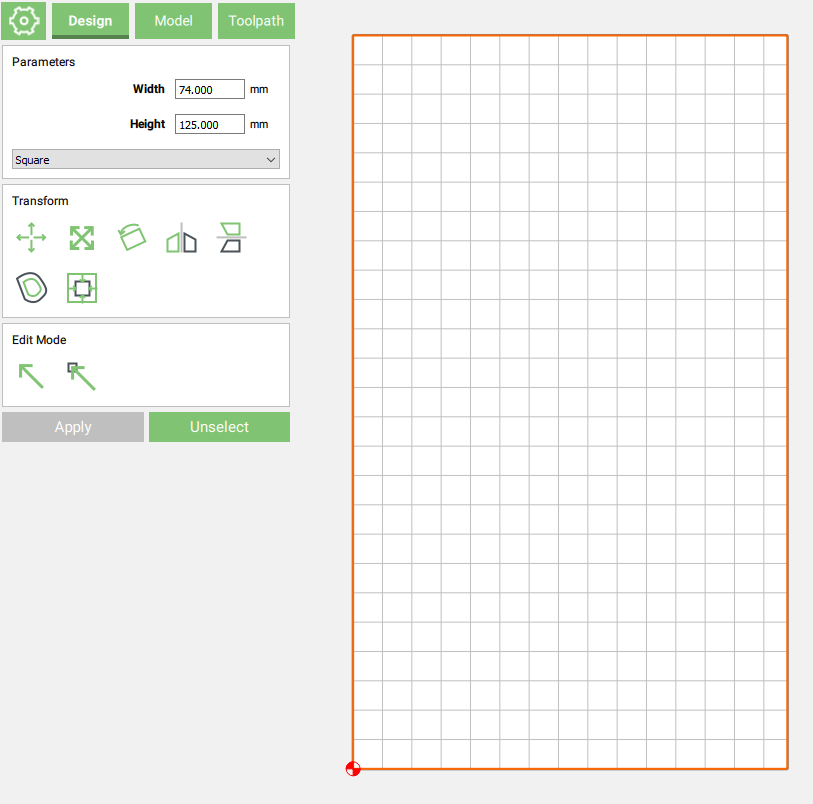
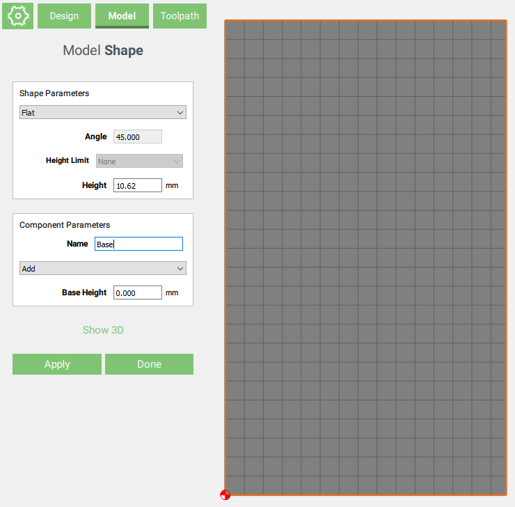
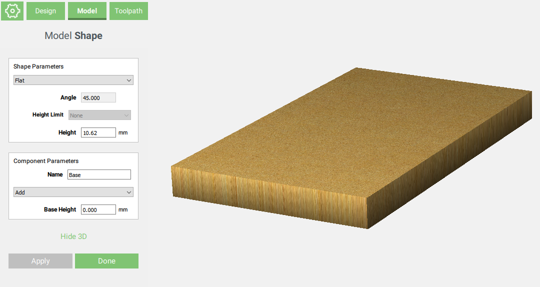
For the “Design” phase, nothing overly difficult here, just lots of symmetrical objects. The quantity of objects gave me lots of objects to 3D model. I’m using a half inch board, so I started with a simple square the size of my project to establish that the lower quarter inch was the (flat) foundation I would build on.
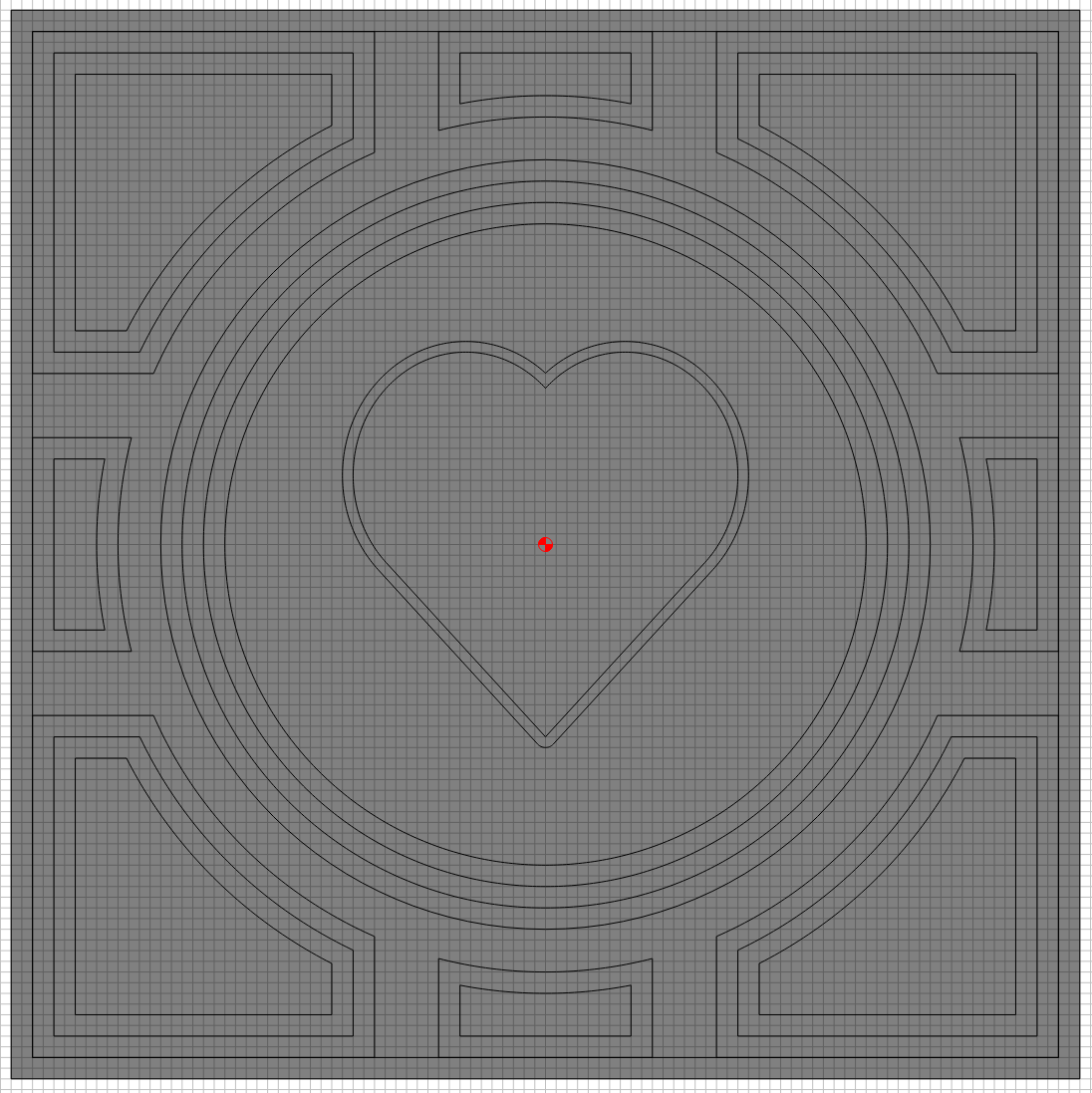
I then modeled the circle in the middle to “Add, Flat” another quarter inch (so half inch total).
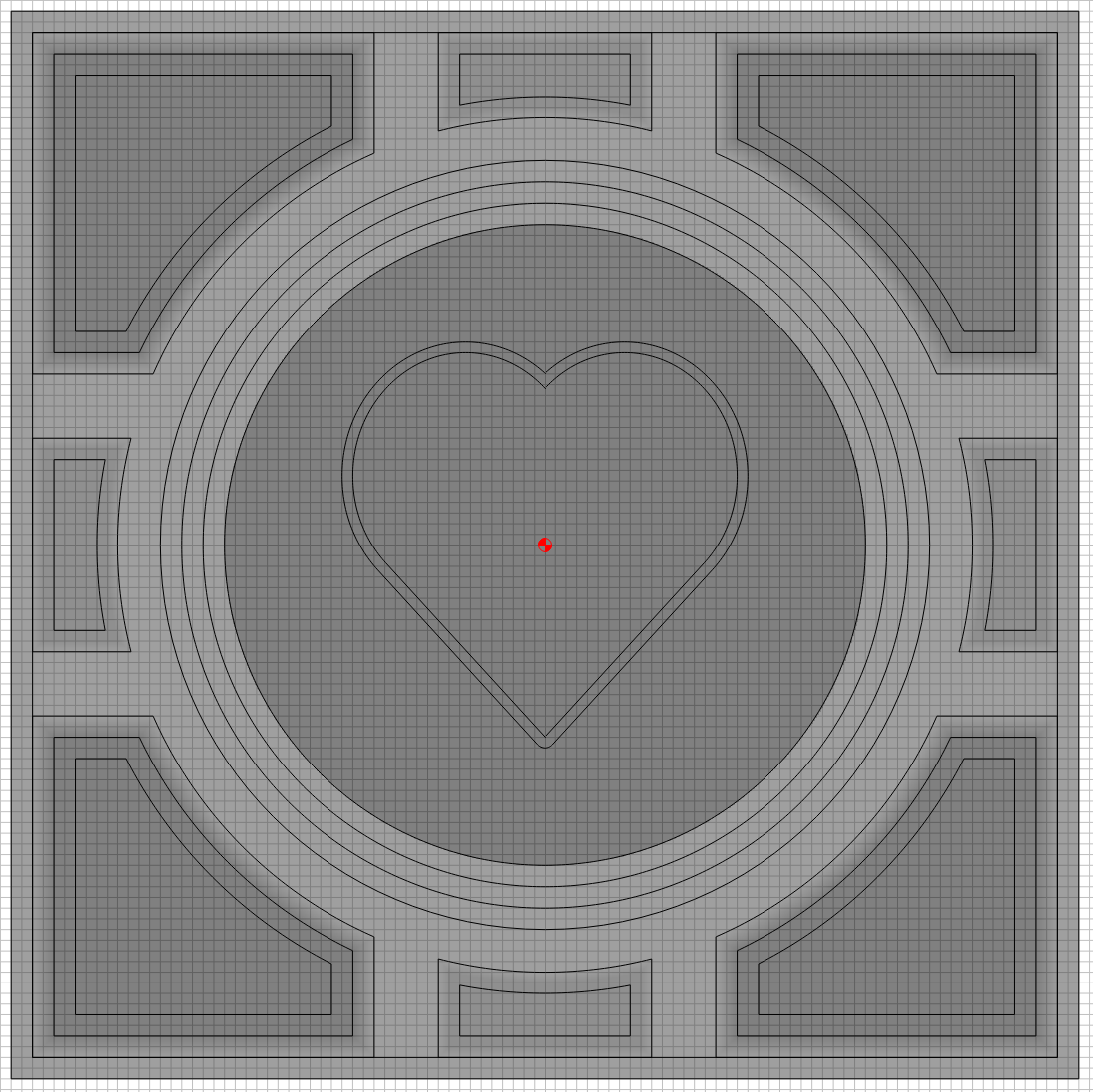
Same with corners, but for those I tried the “Add, Angle”.
Next the middle edges, another “Add, Angle” but instead of adding another quarter I only added a sixteenth (so the top is at nine sixteenths).
Okay, I’ve learned the Flat and Angle, now for a round top object. For that middle rim around the center circle I added another one sixteenth object with a round top.
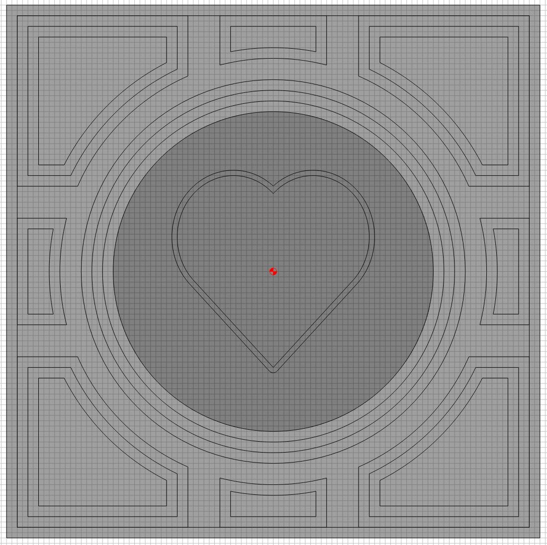
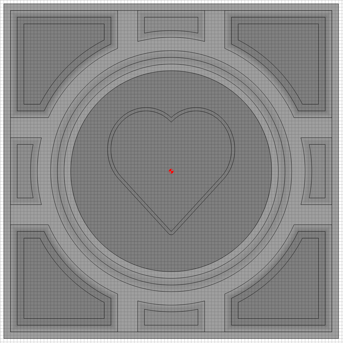
So I think I’ve learned how to Add (as in stack) objects, time to see how Subtract works. That quarter inch tall center circle, that is currently sitting on top of the quarter inch tall square. I wanted to lower that heart area. I probably could have done this more efficiently, but this is a learning experience.
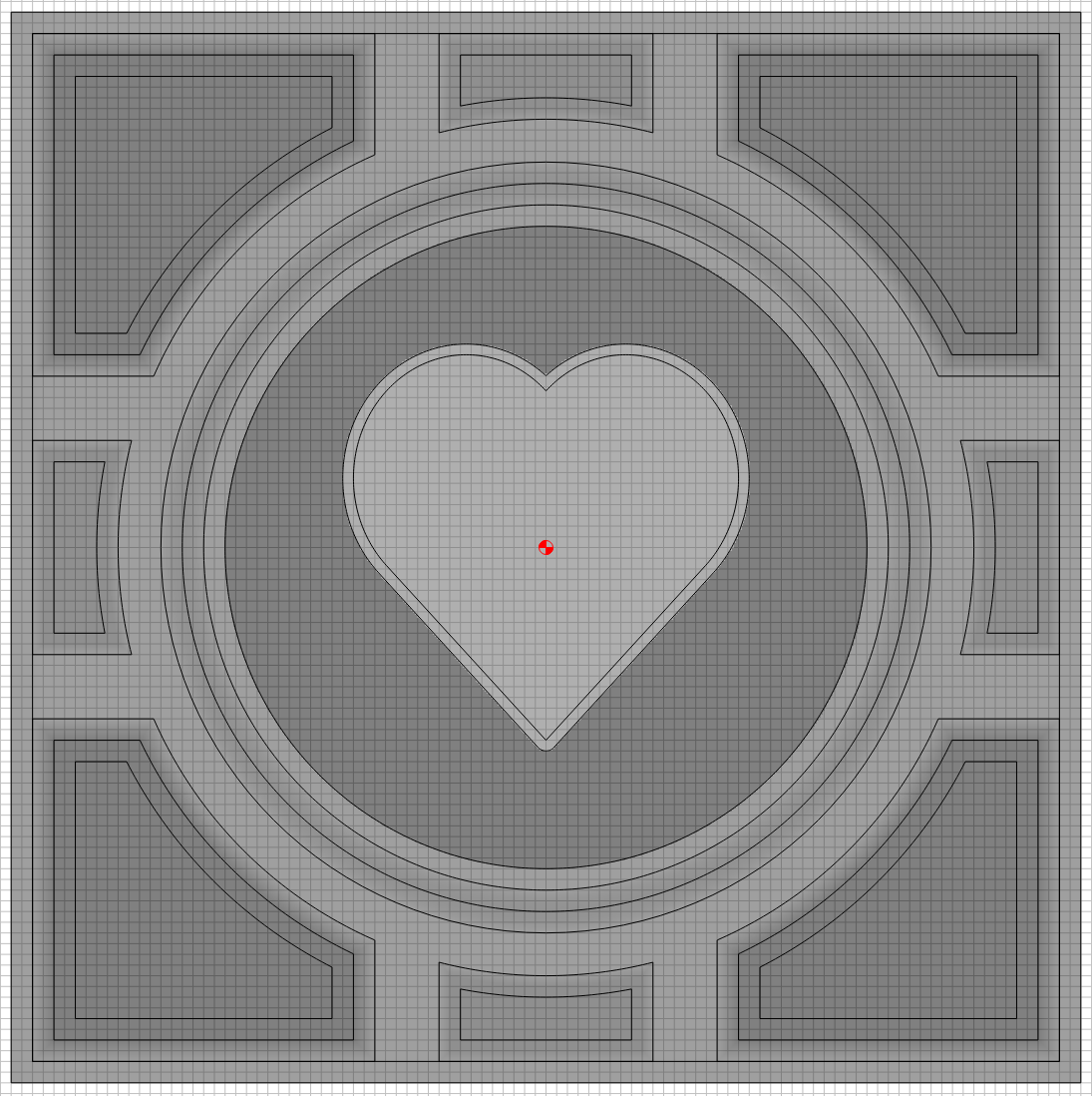
Hey that is looking pretty good, now lets put a forth object on top of those three, I want the heart to stick out with a round top.
I’ll admit that last step took several hours to get right, but that’s okay its’ 2am and my internal clock has been broken for the last 30 days anyway. Now lets move onto the Toolpaths.
You can view the attached .c2d file for details, I’ll switch to showing pictures I took while Carbide Motion was running.
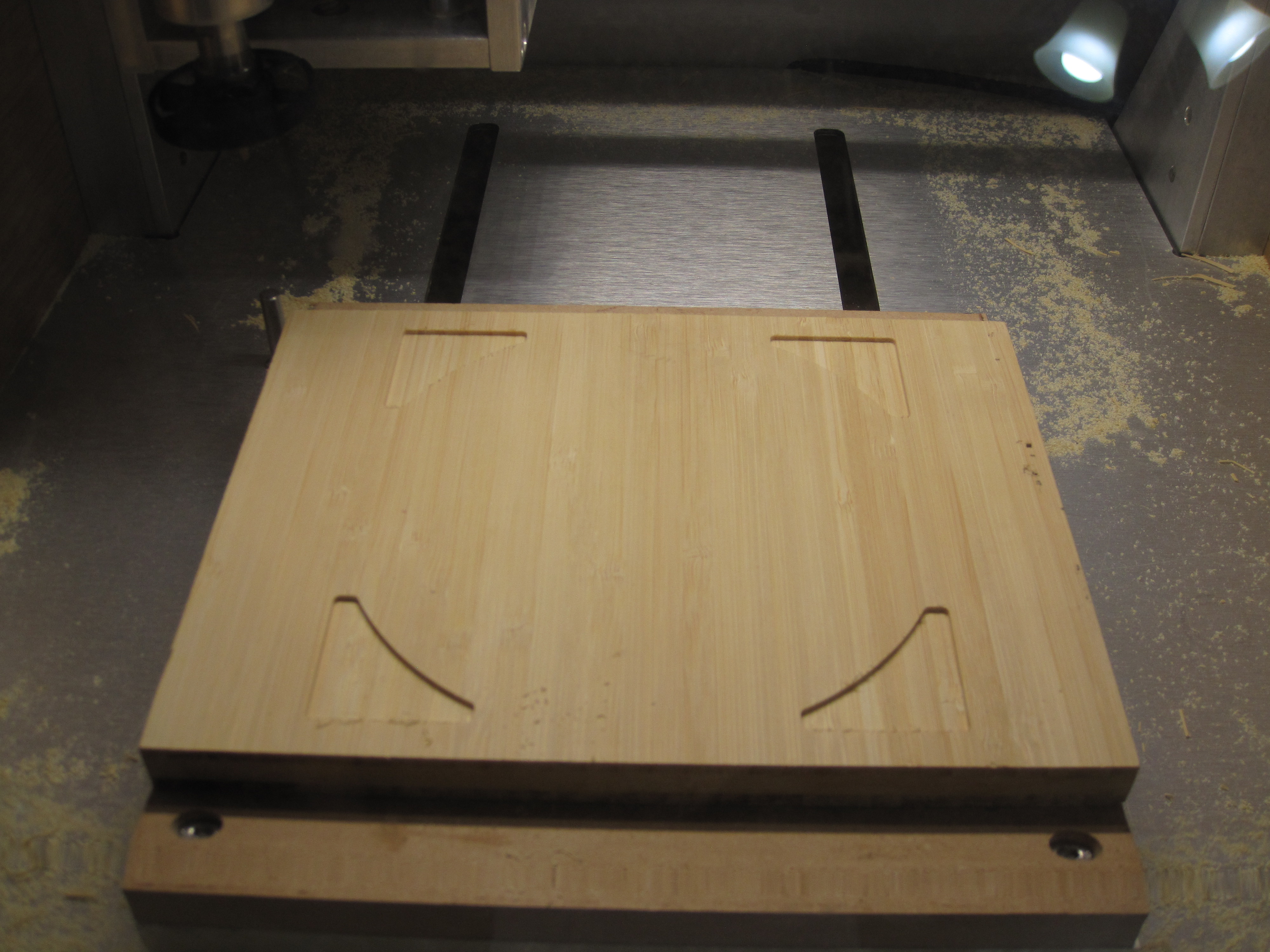
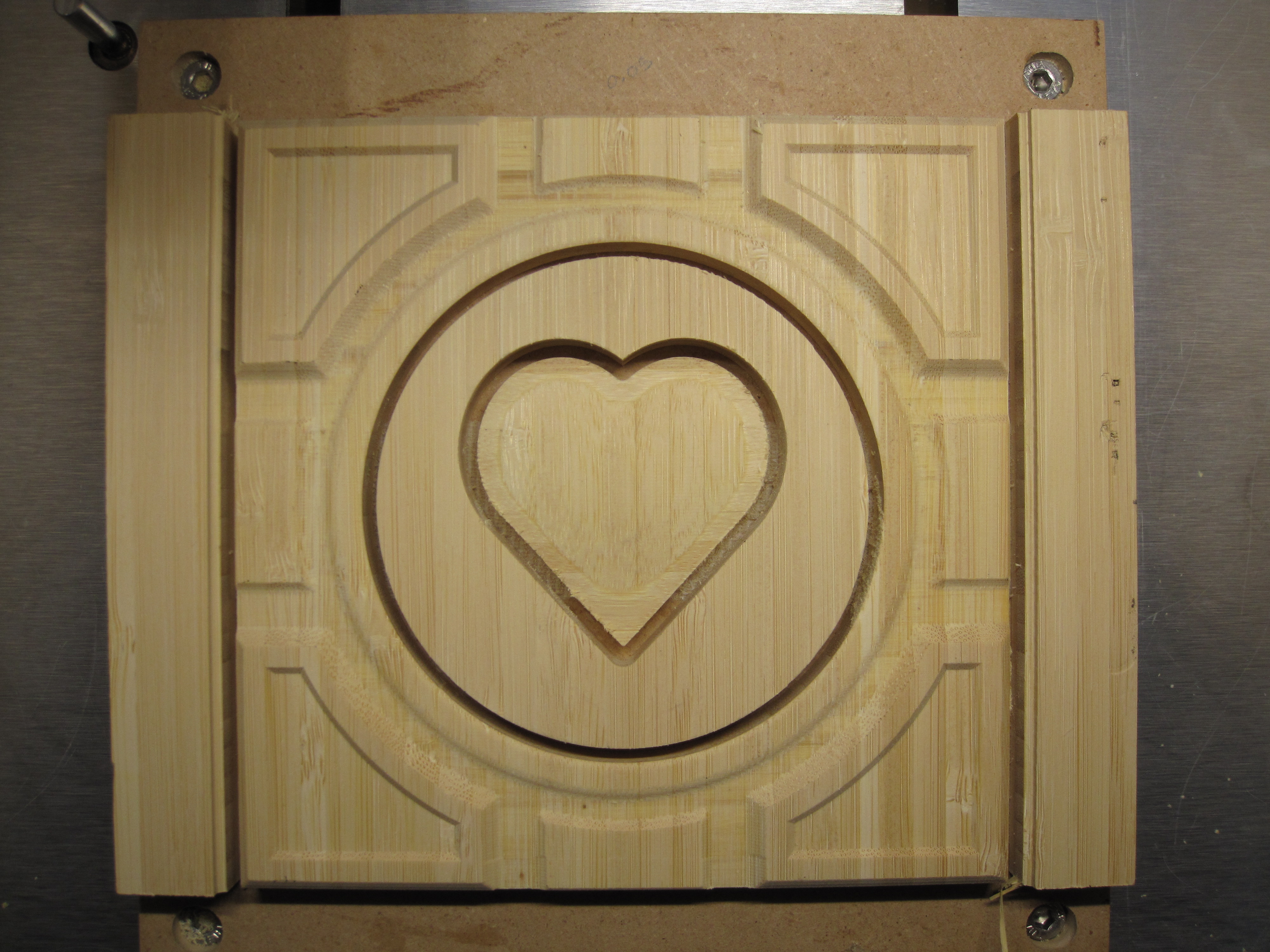
First was a VCarve (also learning that process).
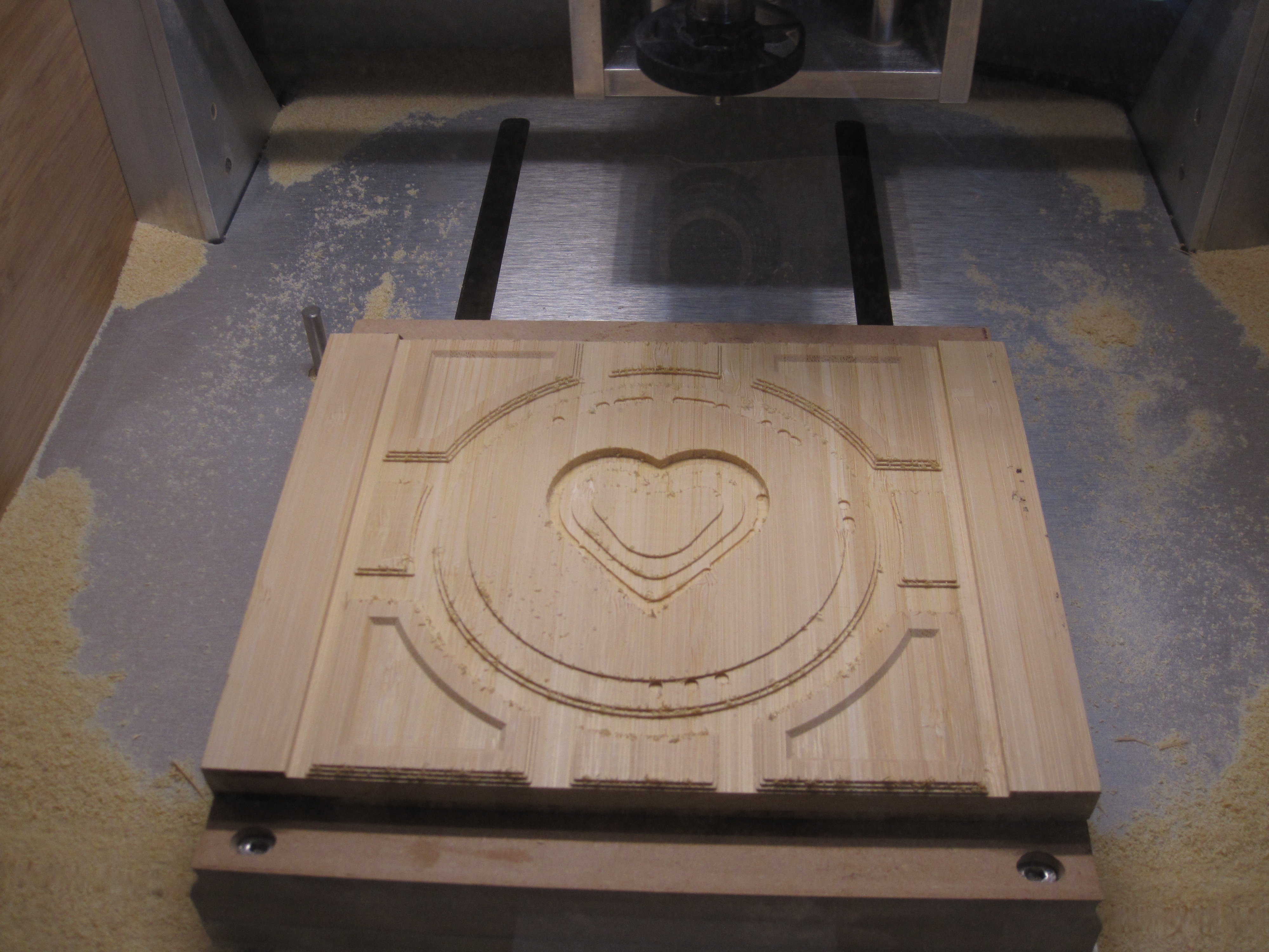
Then the 3D roughing
Then the 3D finish
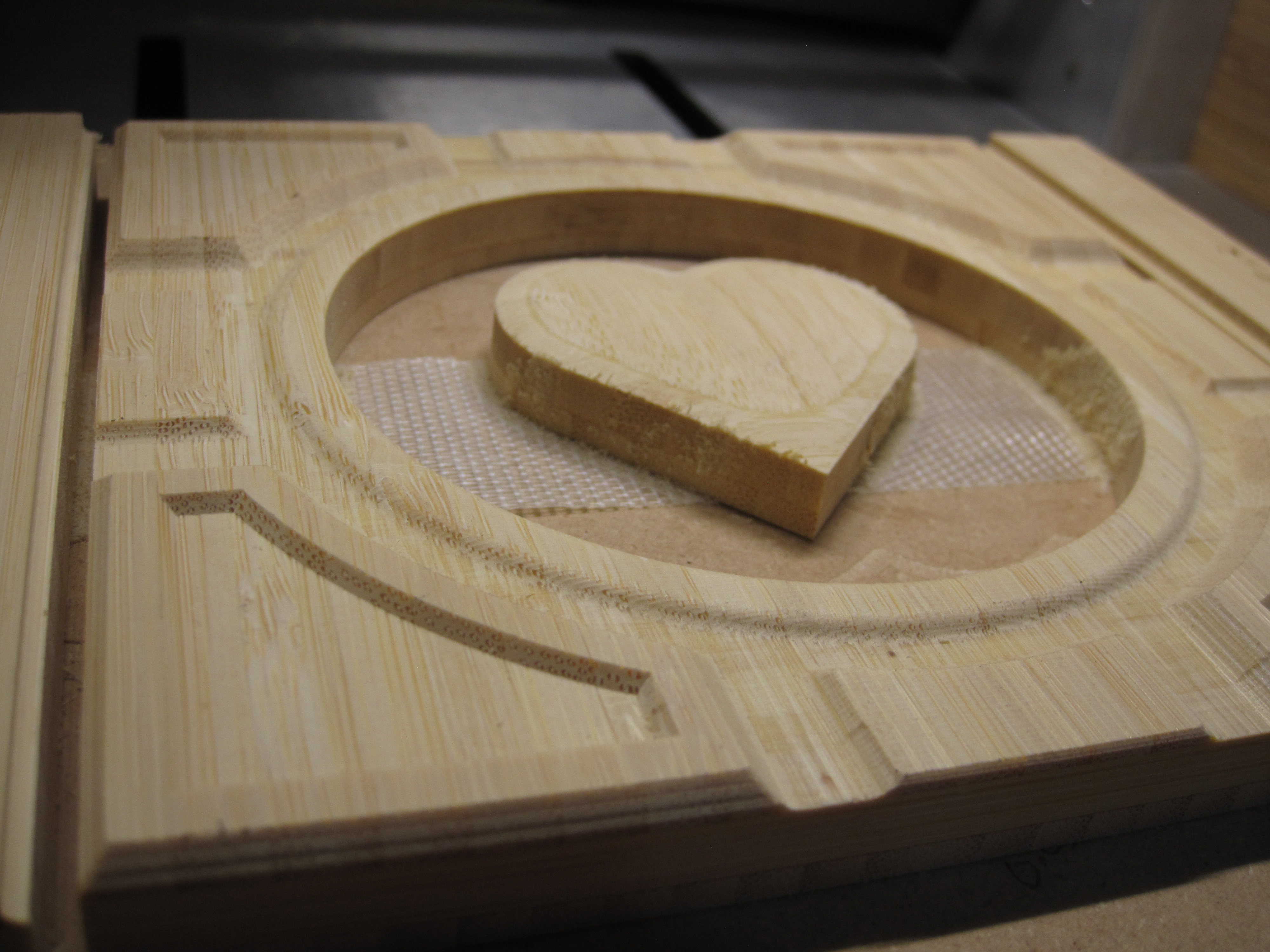
Then cutting out the center circle which I plan on replacing with lexan.
Then cutting out the square
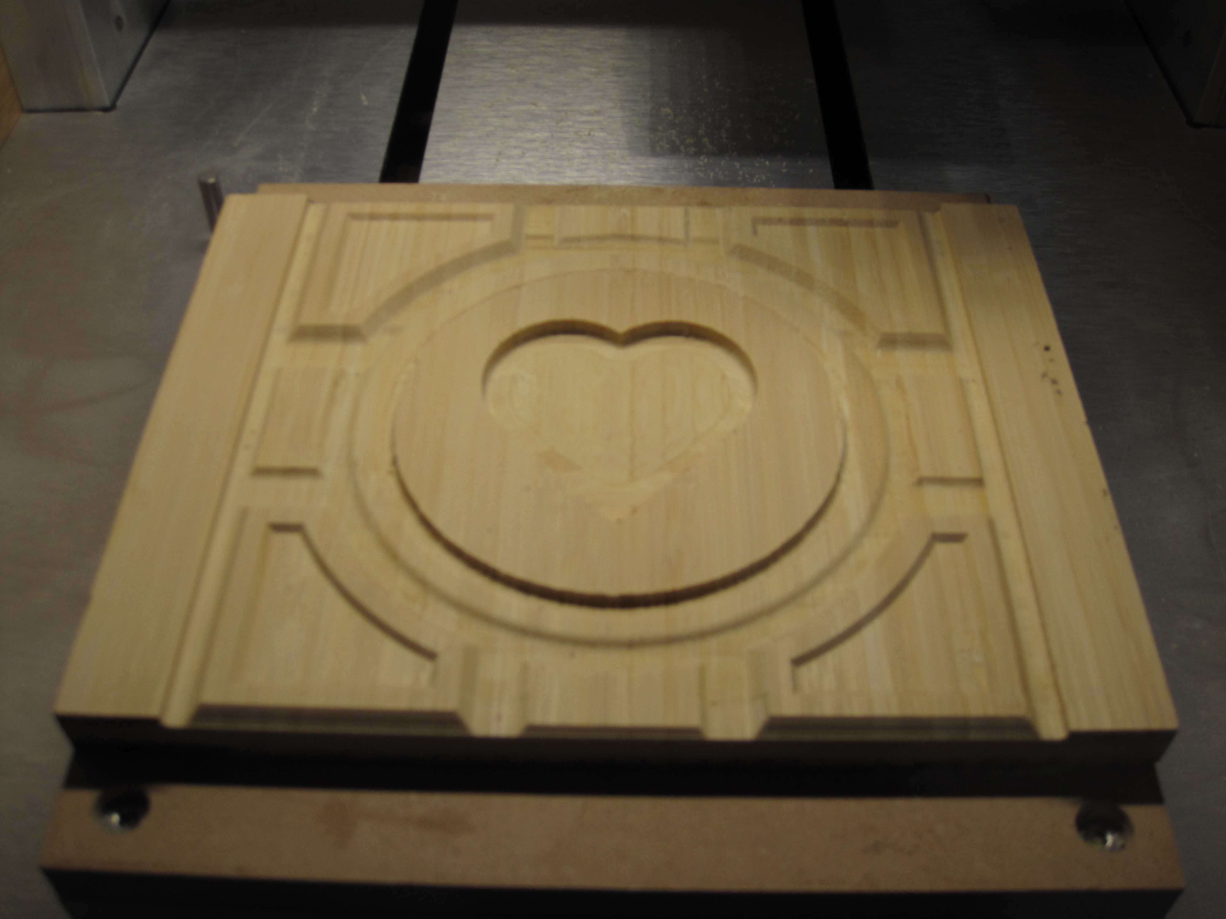
Notice the difference between the (sharp-crisp) v-carve in the corners to the (soft-smooth) round and angle 3D modeled objects. I am very impressed with Carbide 3D’s software.
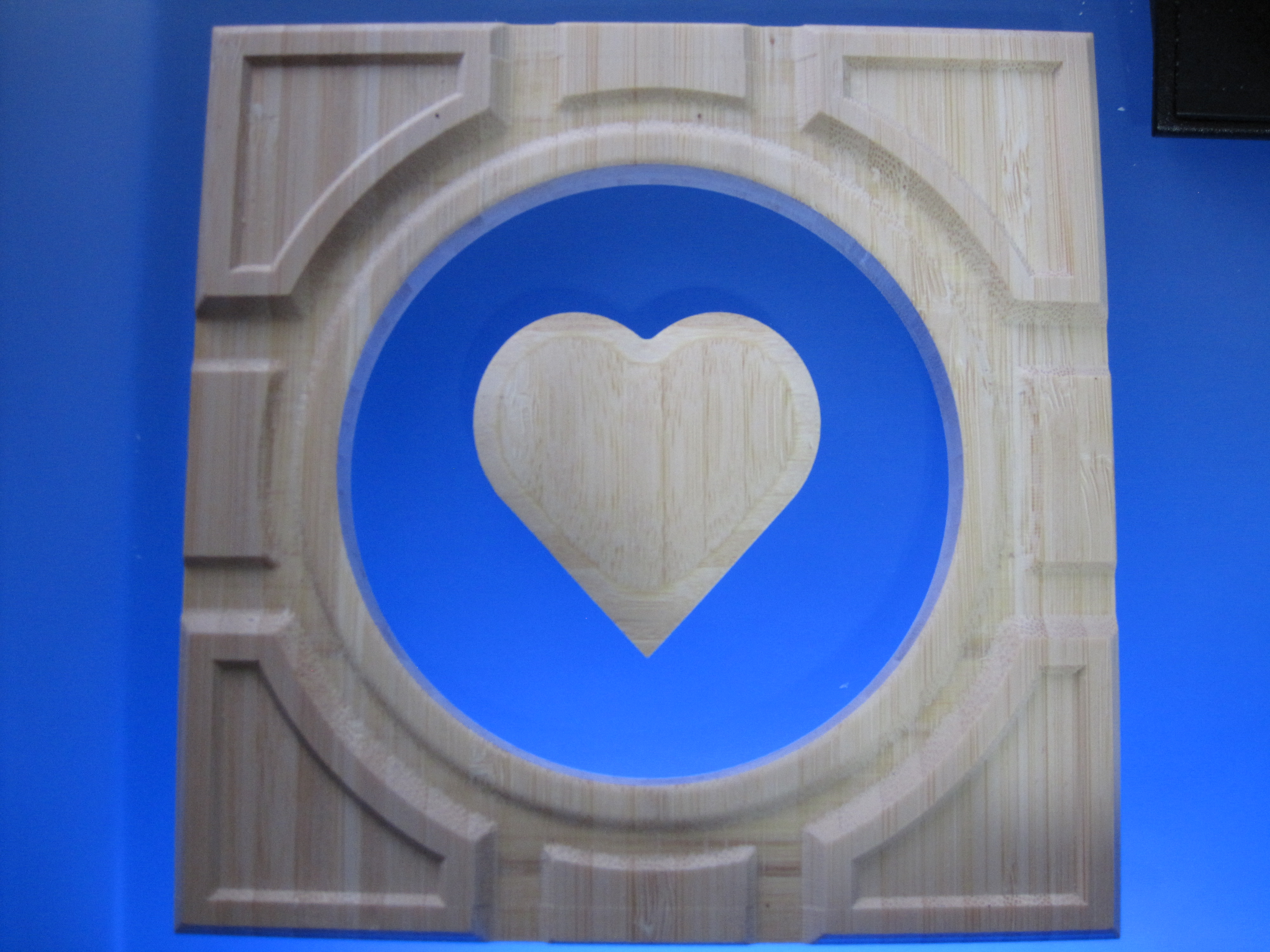
And after some cleanup, here is the result. Now I just need to repeat 5 more times for the other sides.
The Vcarve used a 90 degree v bit, but everything else done with the 1/8 end, 1/8 ball, using the default feeds and speeds built into Carbide Create.
Cube.c2d (1.9 MB)
Was the grain matching of the heart a necessary design element?
Did you consider just cutting the circle out and using the blank for some other project and making the heart out of a contrasting piece of wood?
The real answer is that the design was secondary to the learning experience. I was wanting to learn the 3D modeling and how the add and subtract worked.
However, if you look close I almost pulled off something neat. Notice you can see an outline within the heart. That wasn’t machined, that is where the bamboo grain alternates in the wood I am using. The outer edges of the heart has horizontal grain while the inside has vertical. If I were to start over I would adjust the model to make everything that is raised fall into that horizontal grain and everything that is lowered go down into the vertical grain. I missed it by less than 1/32.
Or is it a companion cube from portal? WE MUST KNOW THE TRUTH!
Looks great by the way!