Community challenge #7: Carbide Create Pro (closed)

I started learning to use Carbide Create on March 15th, which for me was day one of “social distancing”. Carbide Create is the first CAD software I’ve used, before this my kid did the CAD work and I focused on knowing how to operate the Nomad 883. The kid is off at college, so I lost my (free) CAD designer which is why I am just now learning that side, but we have owned the Nomad since Christmas of 2014.
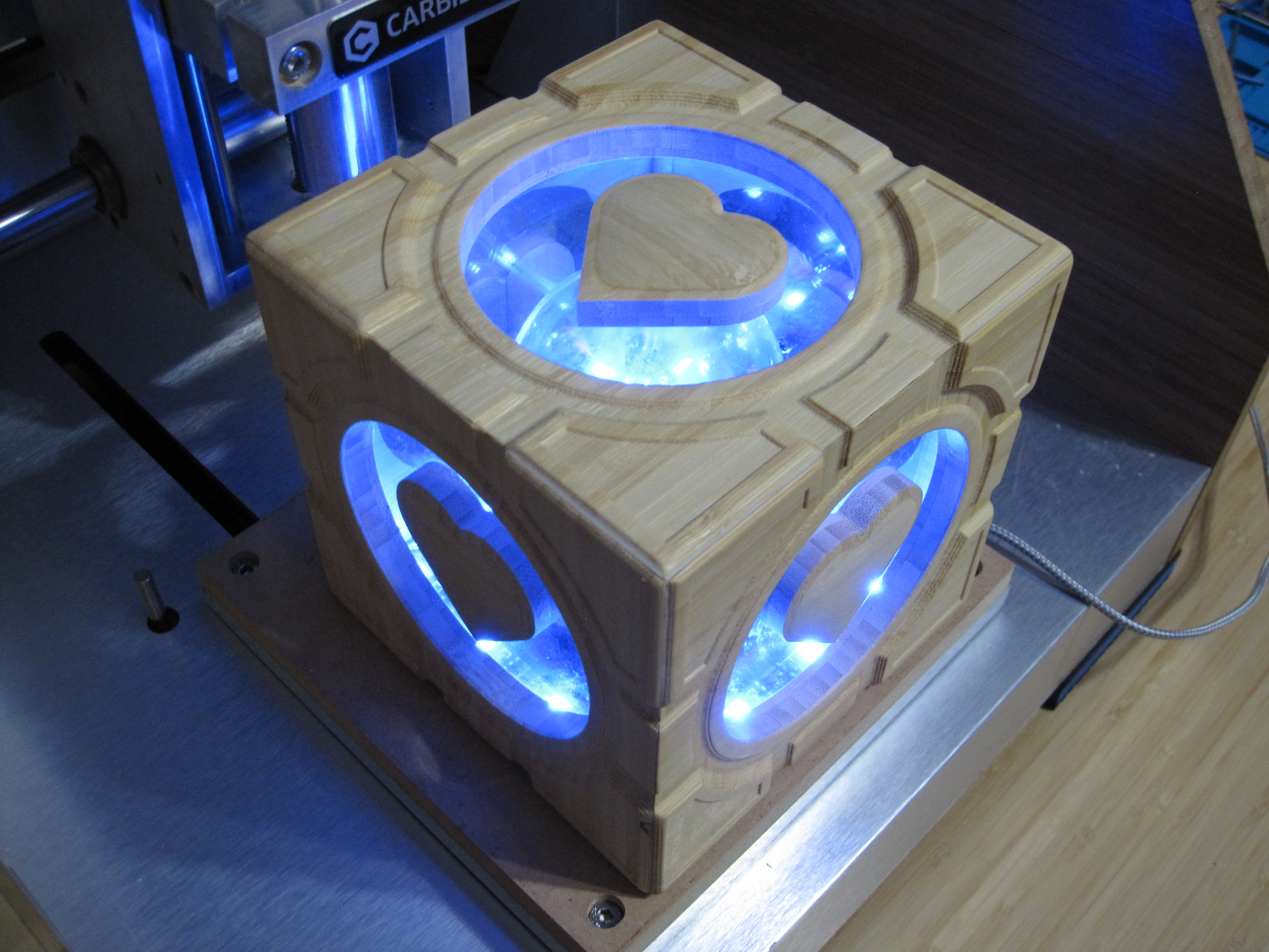
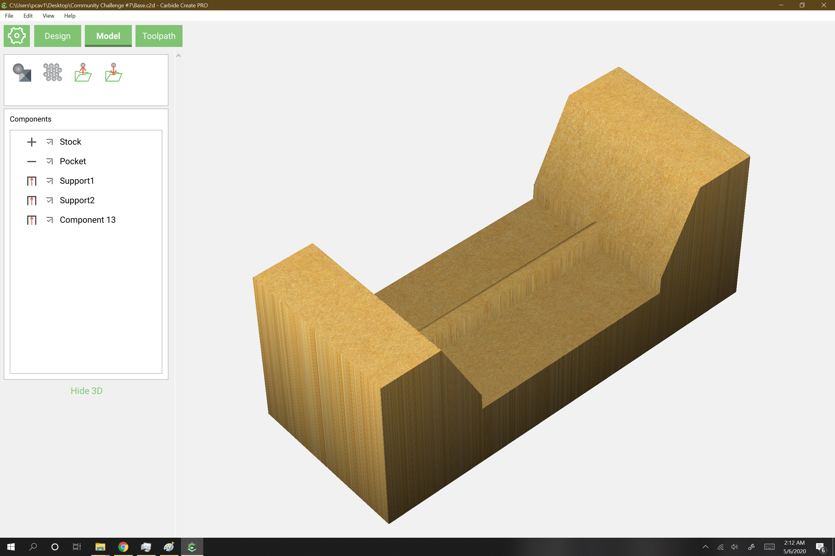
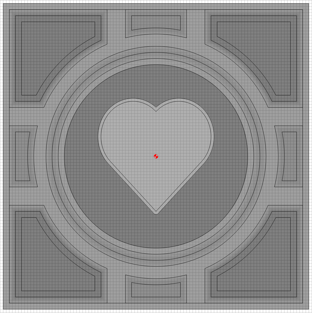
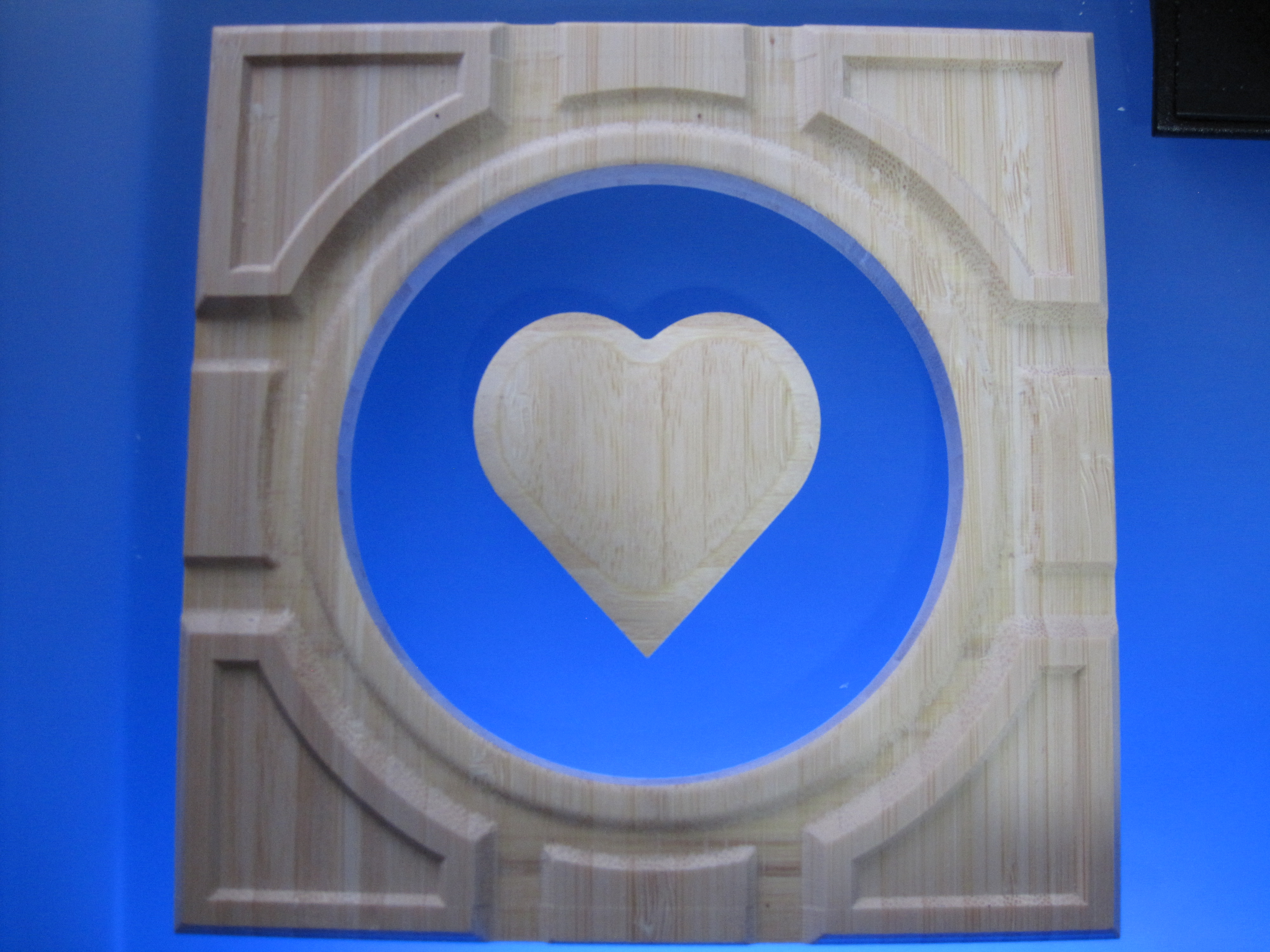
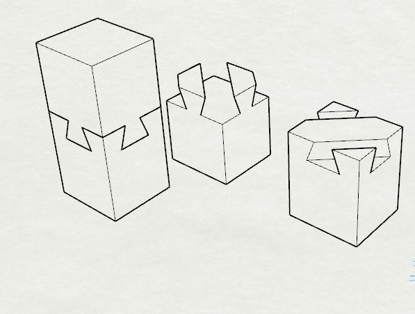
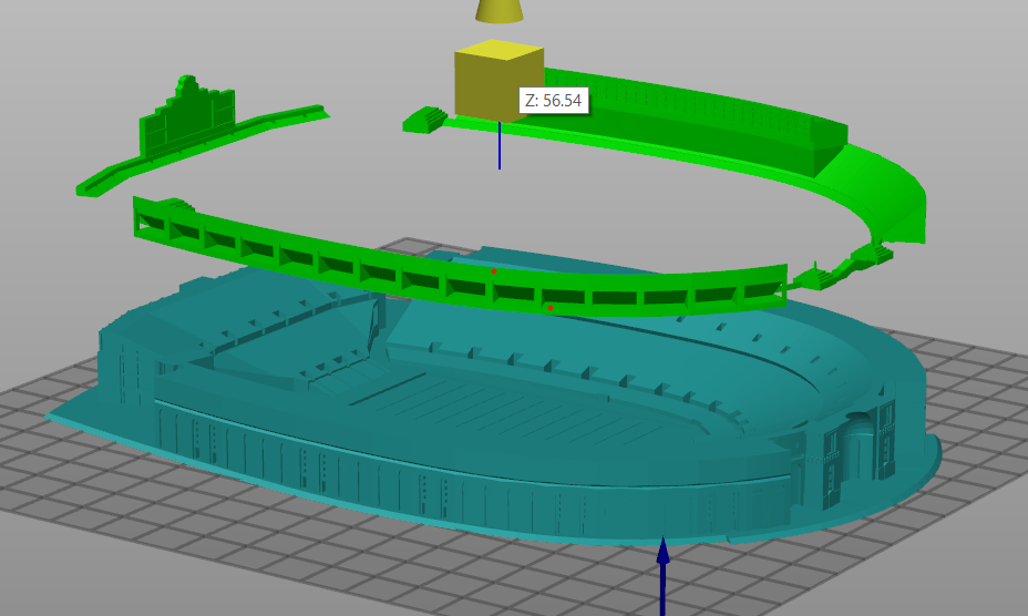
Two days ago I started learning how to use the Pro 3D modeling features in Carbide Create, what you are about to see is the result of my efforts , yes this is my first “pro” design so be gentle. Nothing was imported, everything was created within Carbide Create using simple objects and the built in 3D modeling. The design is from one of my kid’s favorite computer games, what you are looking at is one side of what will eventually be a six sided cube.

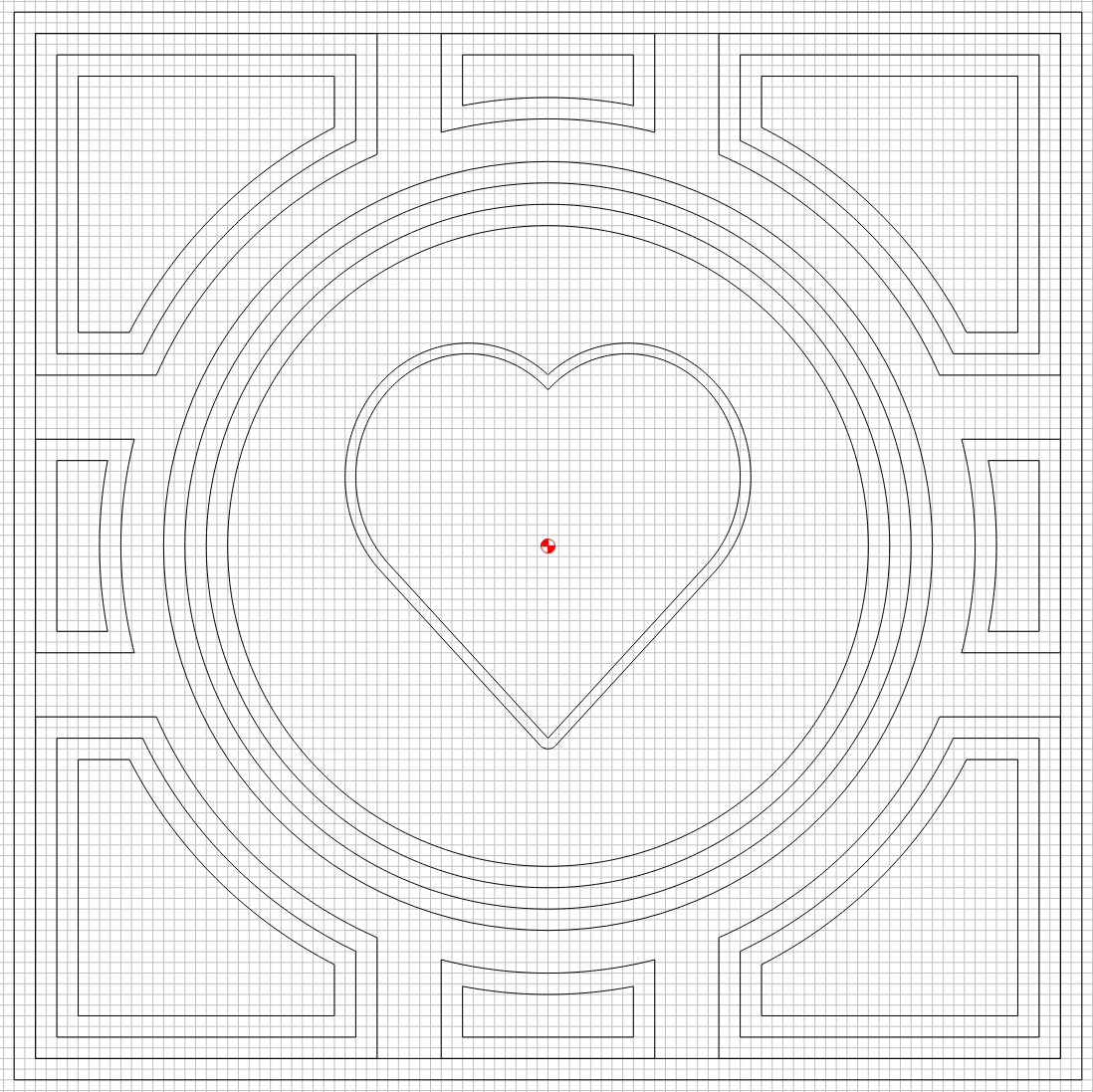
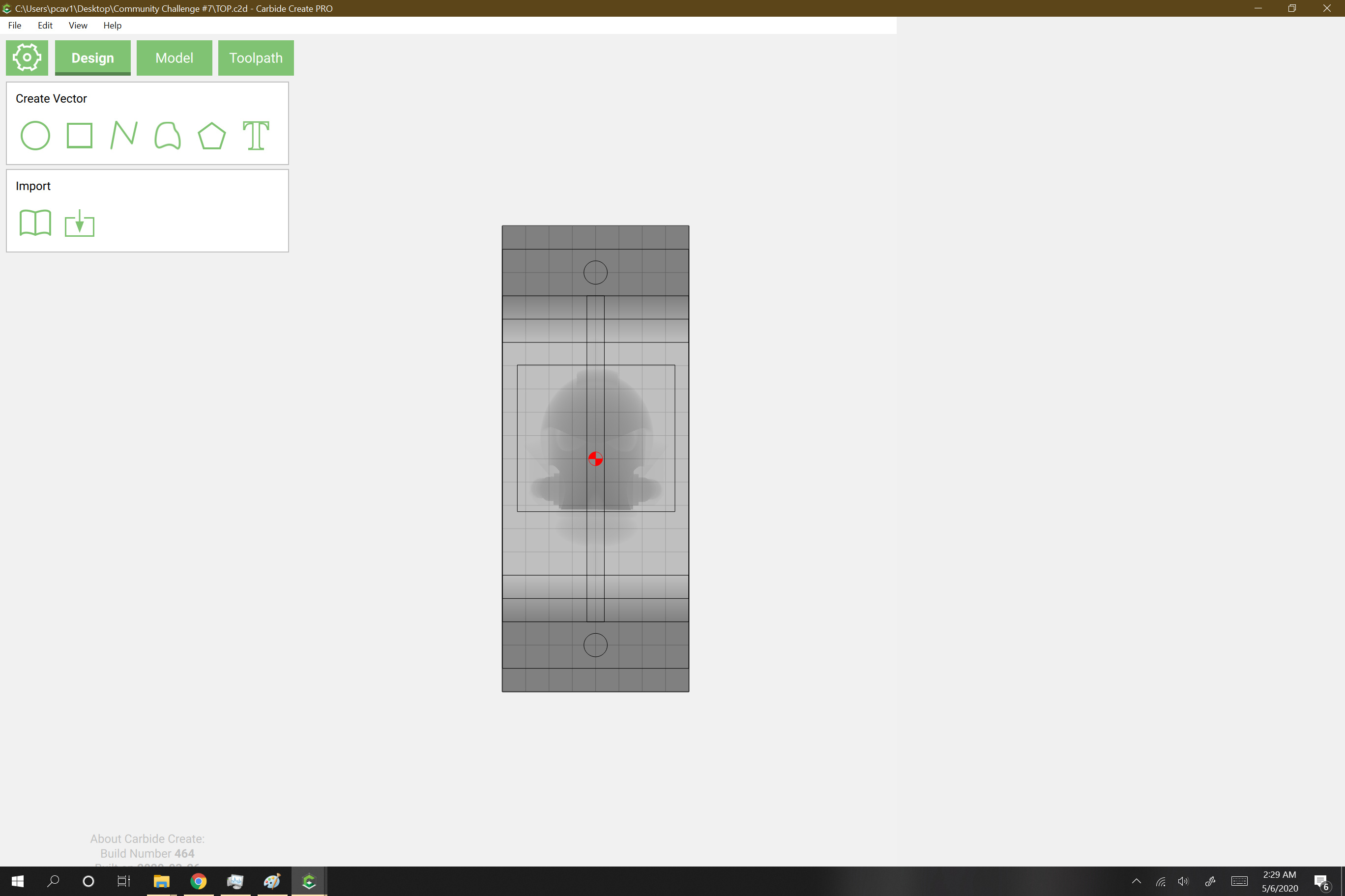
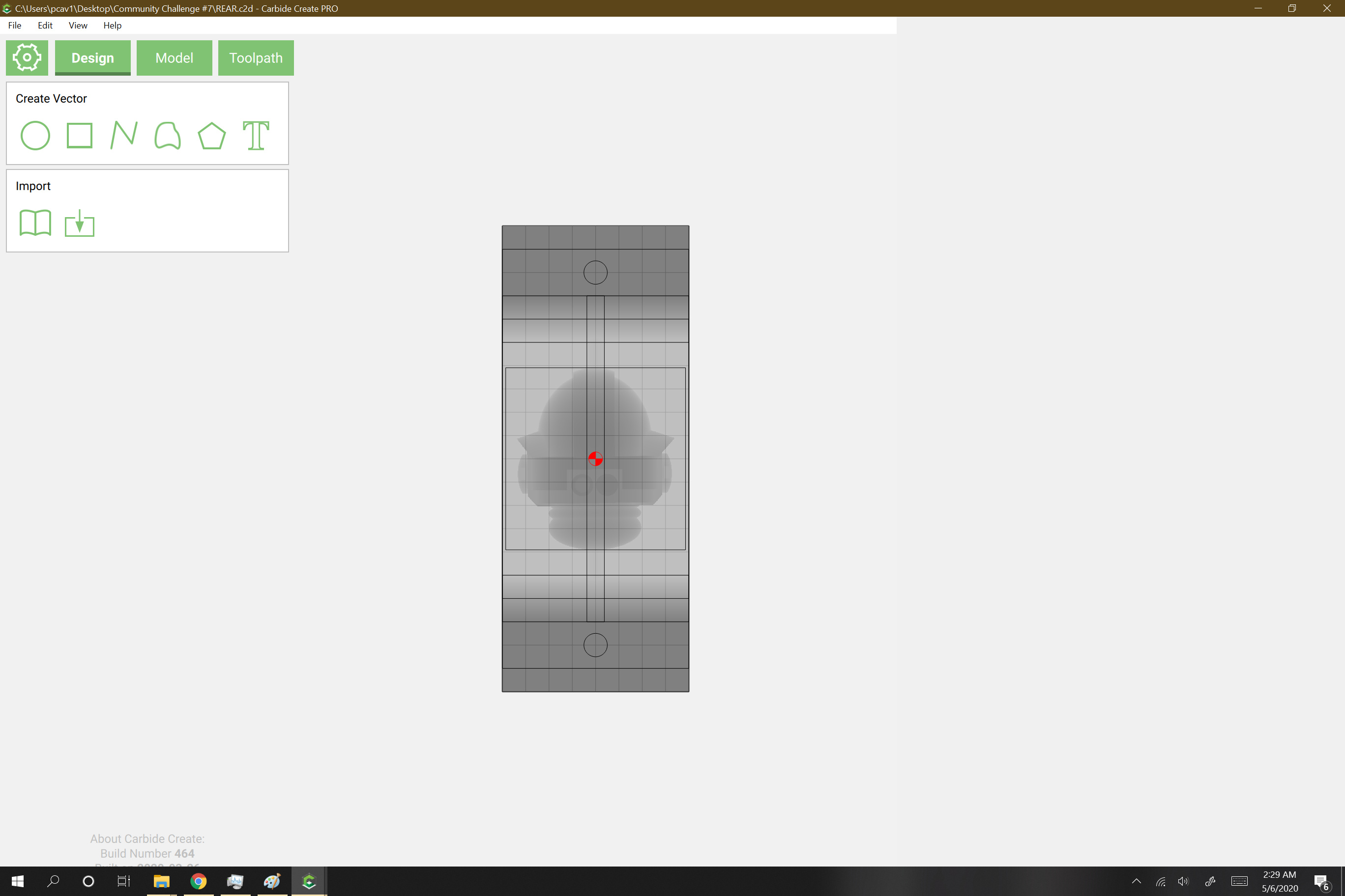
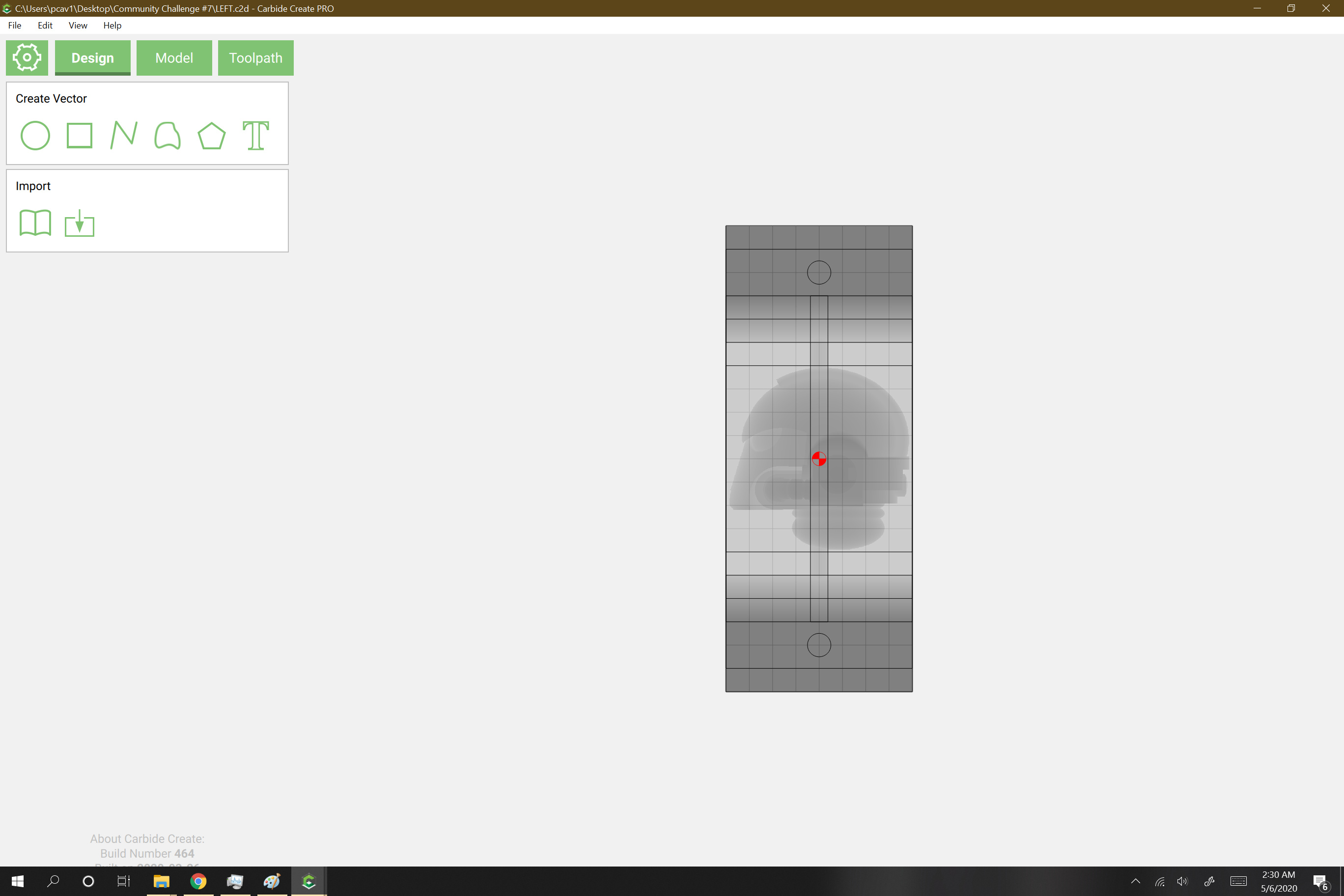
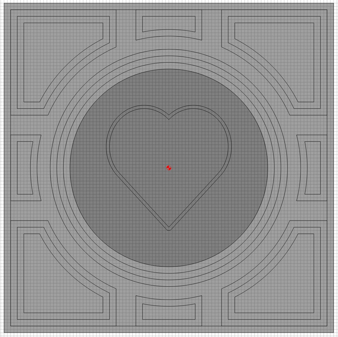
For the “Design” phase, nothing overly difficult here, just lots of symmetrical objects. The quantity of objects gave me lots of objects to 3D model. I’m using a half inch board, so I started with a simple square the size of my project to establish that the lower quarter inch was the (flat) foundation I would build on.

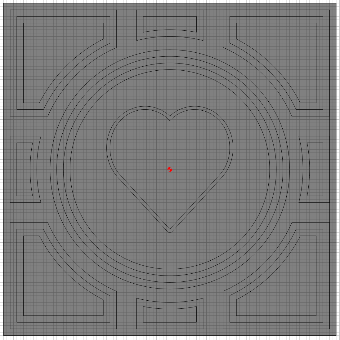
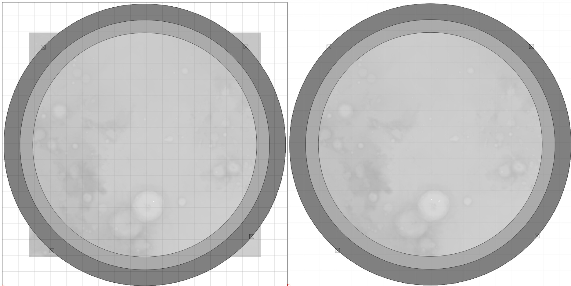
I then modeled the circle in the middle to “Add, Flat” another quarter inch (so half inch total).

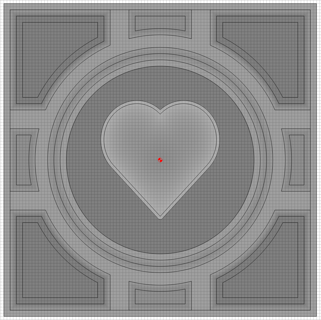
Same with corners, but for those I tried the “Add, Angle”.

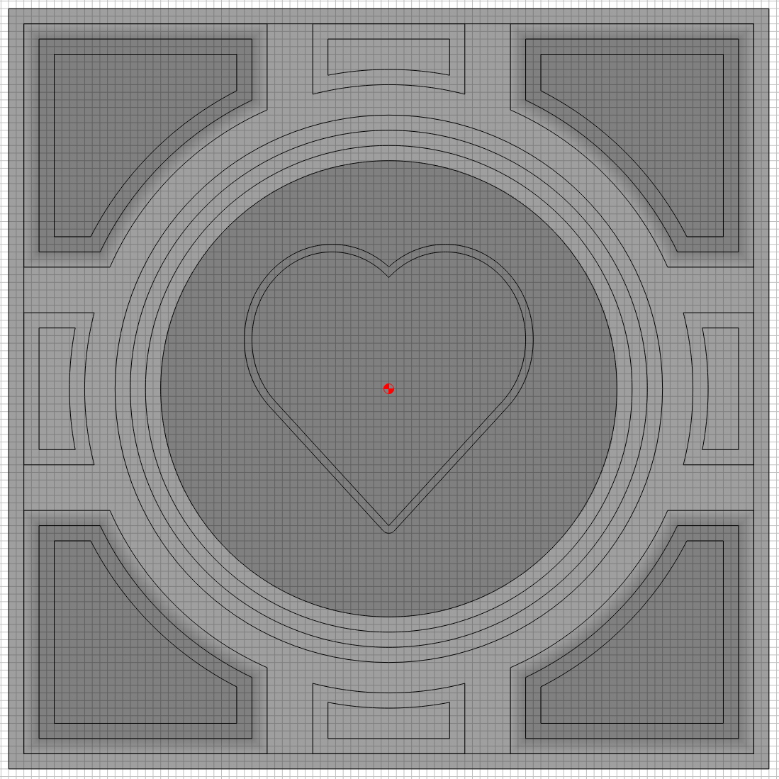
Next the middle edges, another “Add, Angle” but instead of adding another quarter I only added a sixteenth (so the top is at nine sixteenths).

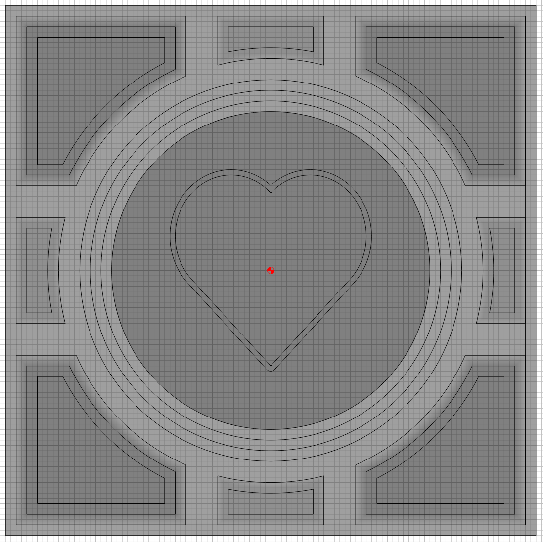
Okay, I’ve learned the Flat and Angle, now for a round top object. For that middle rim around the center circle I added another one sixteenth object with a round top.

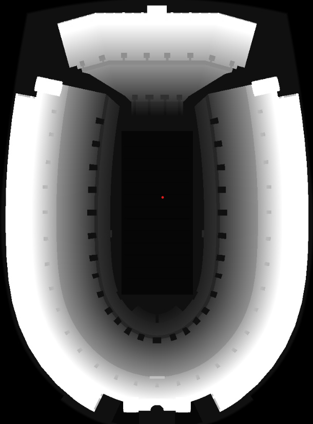
So I think I’ve learned how to Add (as in stack) objects, time to see how Subtract works. That quarter inch tall center circle, that is currently sitting on top of the quarter inch tall square. I wanted to lower that heart area. I probably could have done this more efficiently, but this is a learning experience.

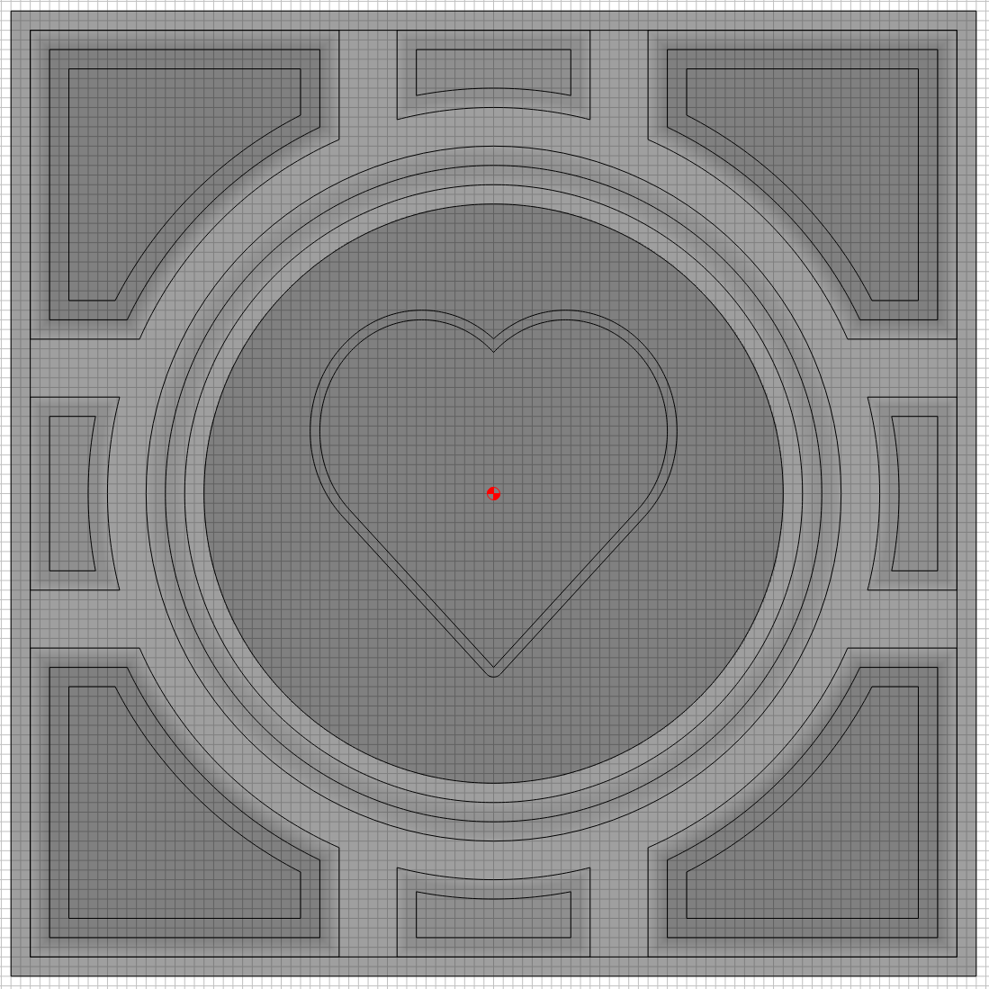
Hey that is looking pretty good, now lets put a forth object on top of those three, I want the heart to stick out with a round top.

I’ll admit that last step took several hours to get right, but that’s okay its’ 2am and my internal clock has been broken for the last 30 days anyway. Now lets move onto the Toolpaths.

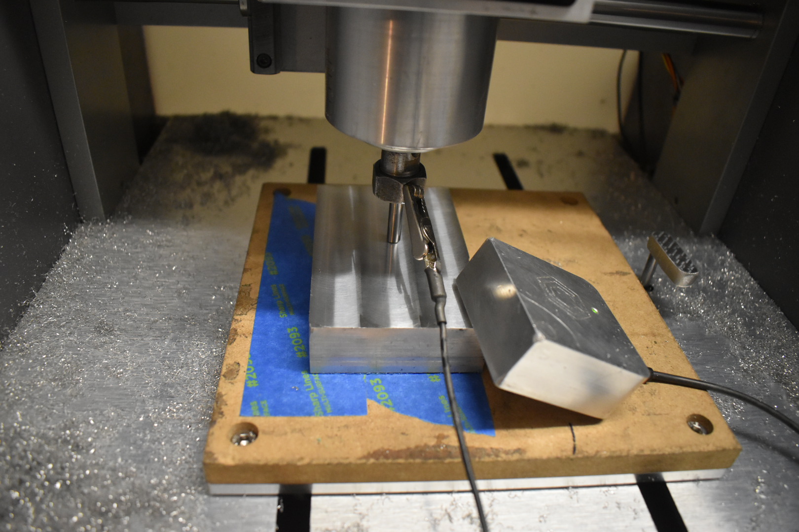
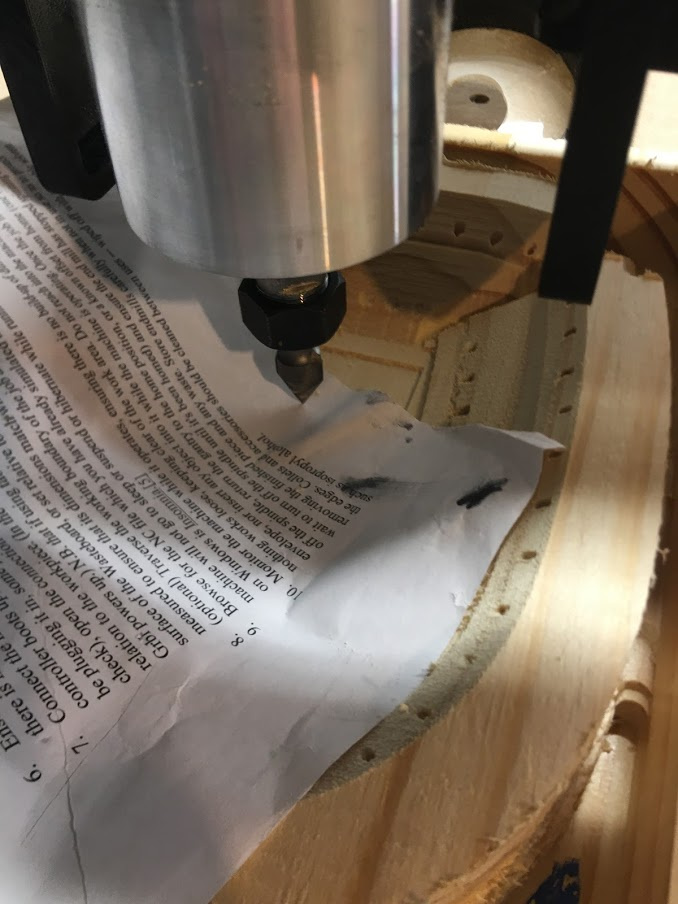
You can view the attached .c2d file for details, I’ll switch to showing pictures I took while Carbide Motion was running.

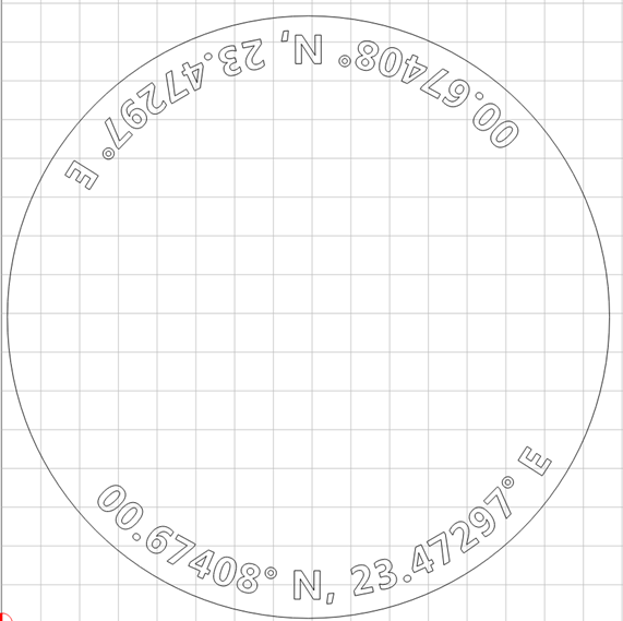
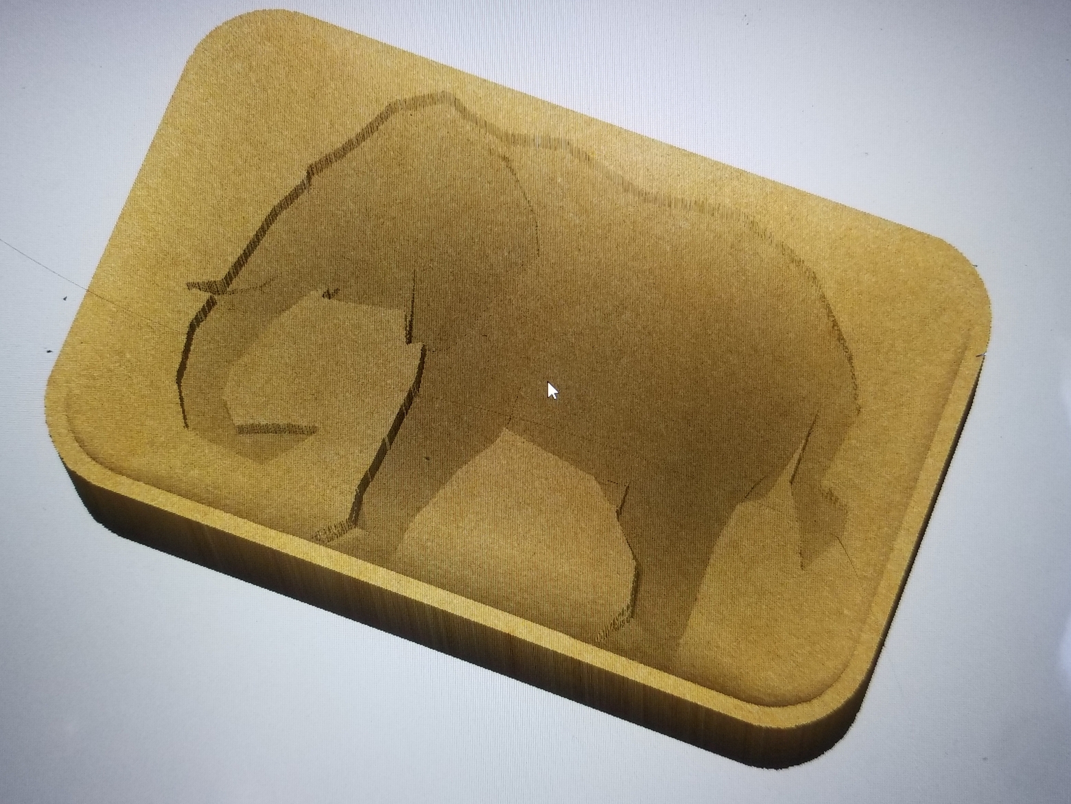
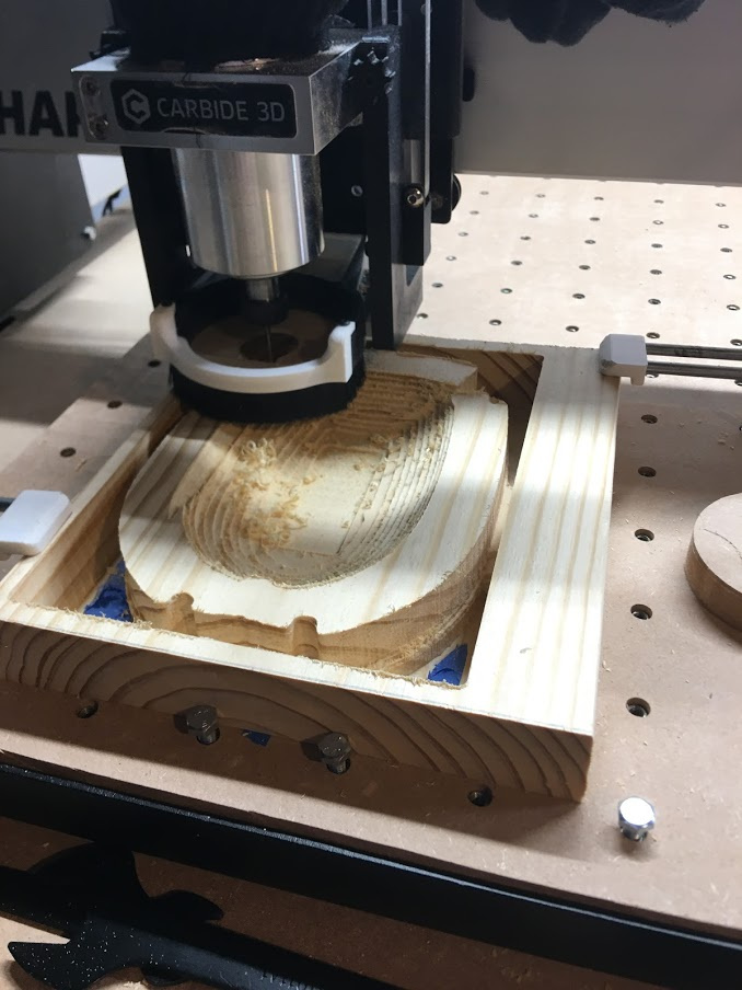
First was a VCarve (also learning that process).

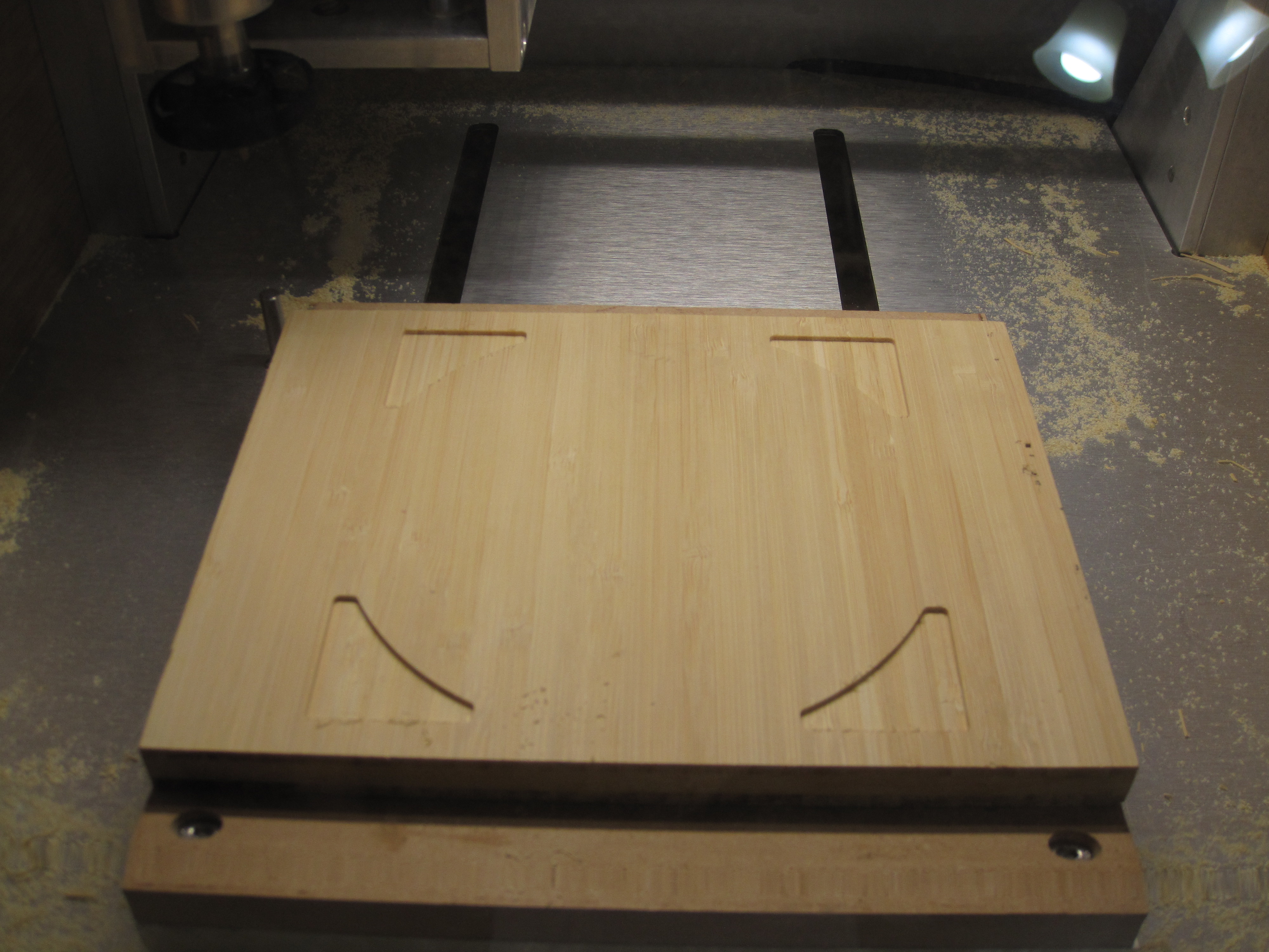
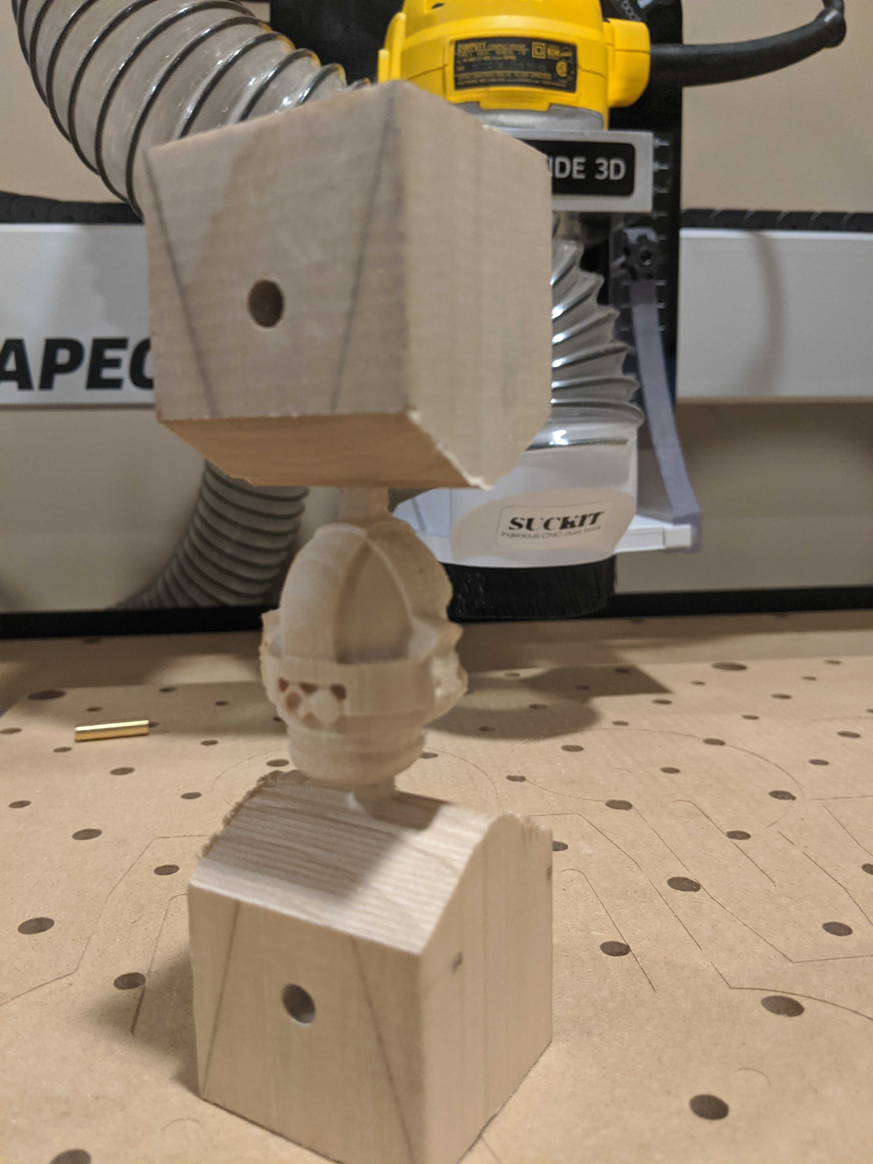
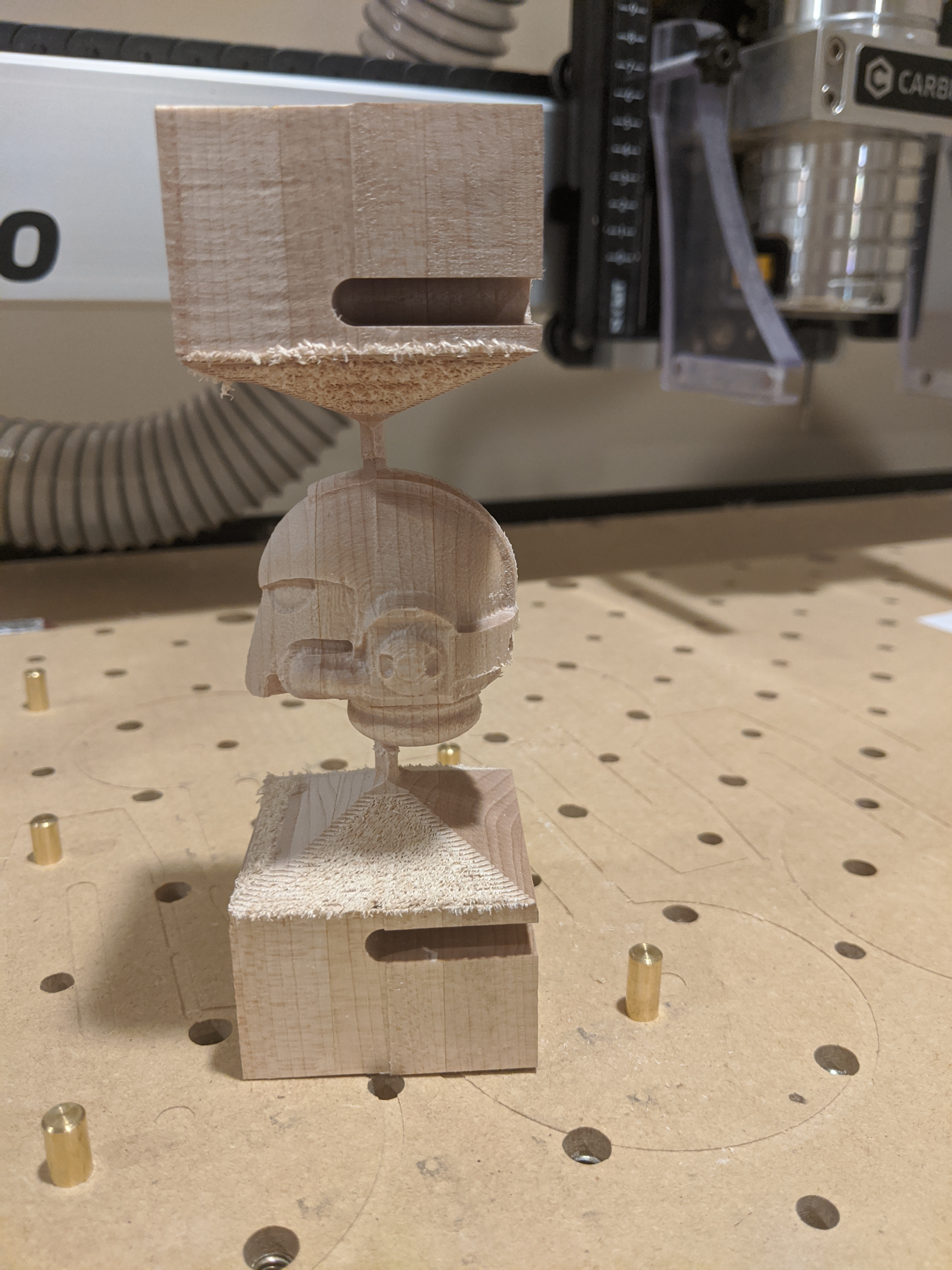
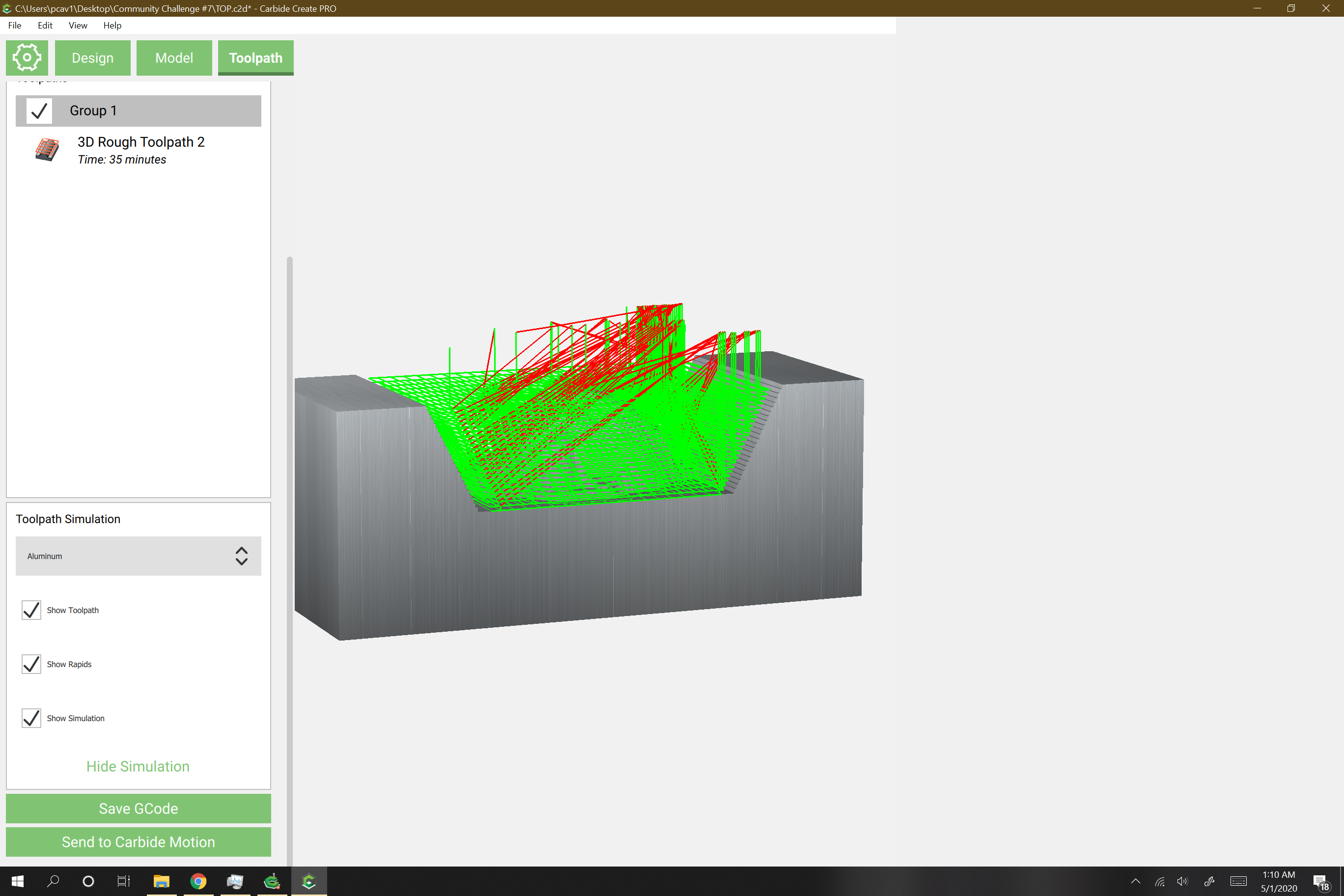
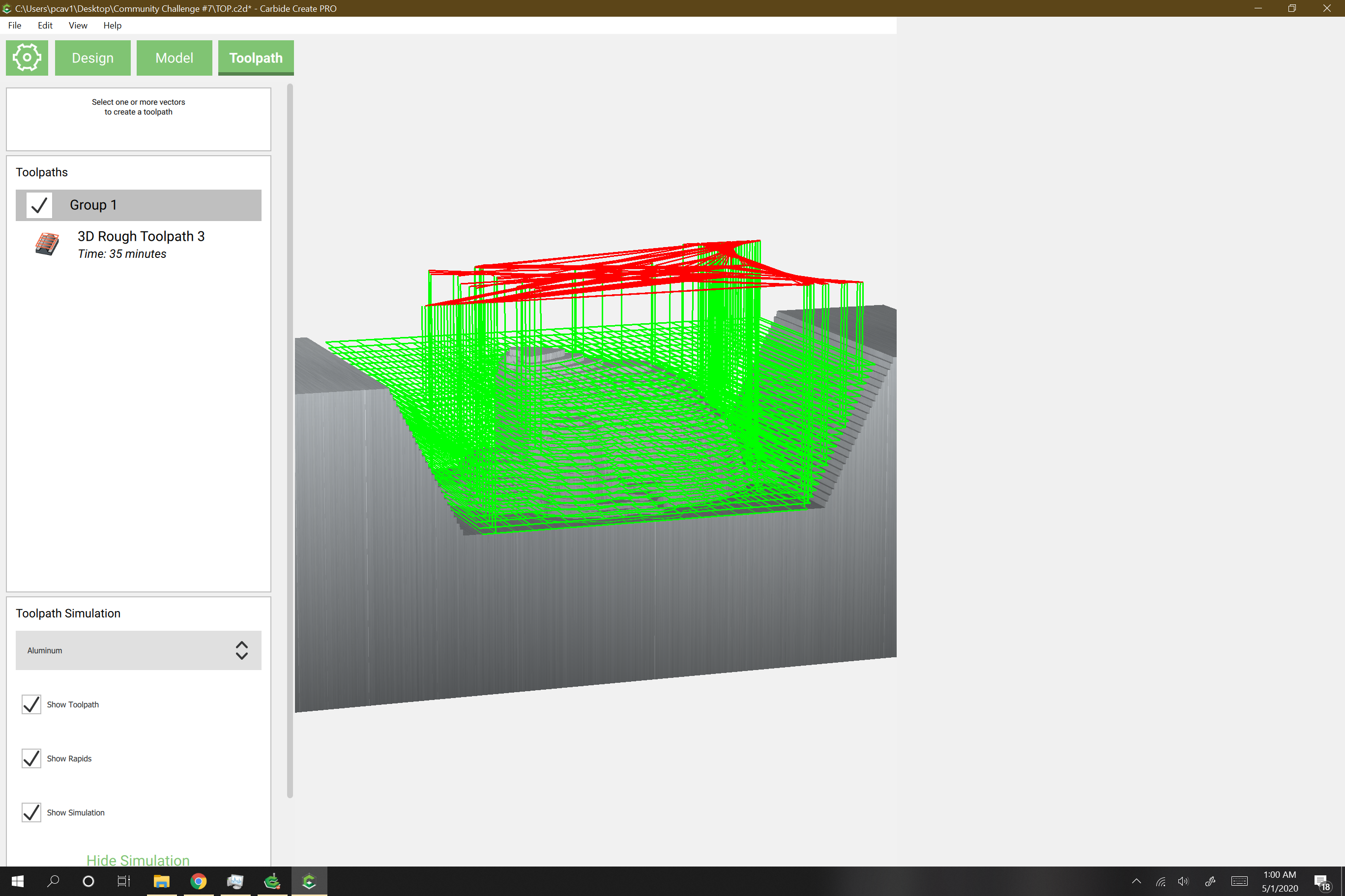
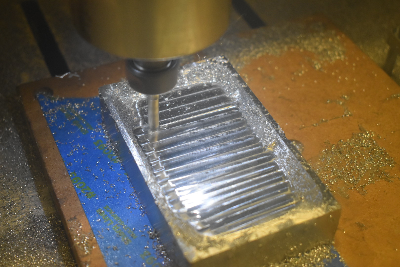
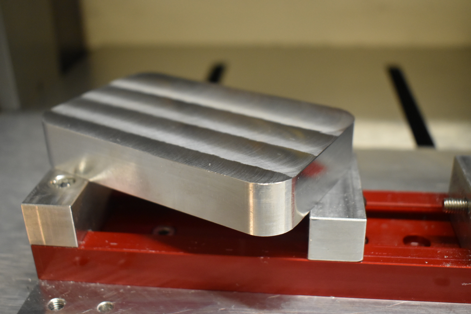
Then the 3D roughing
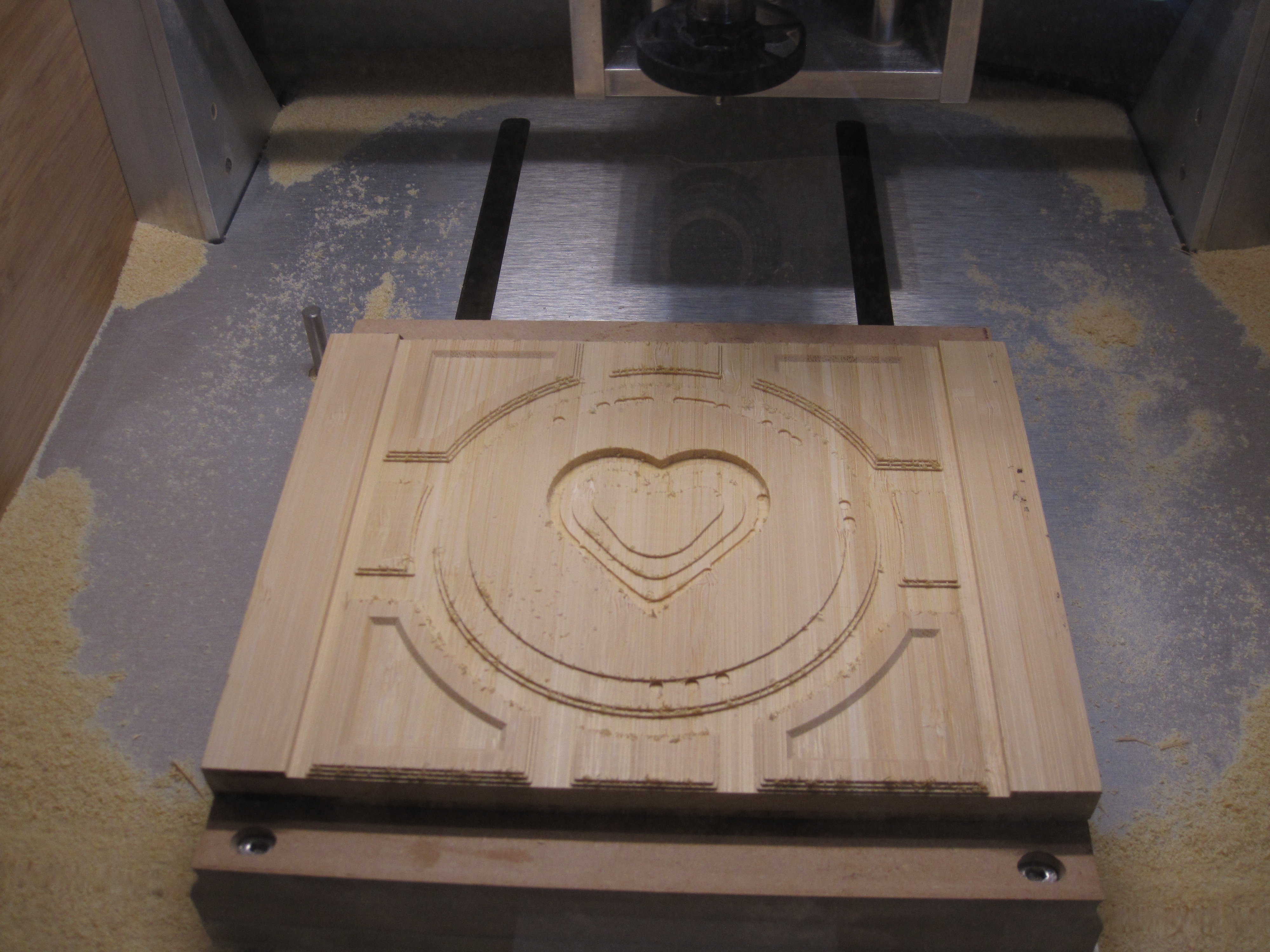
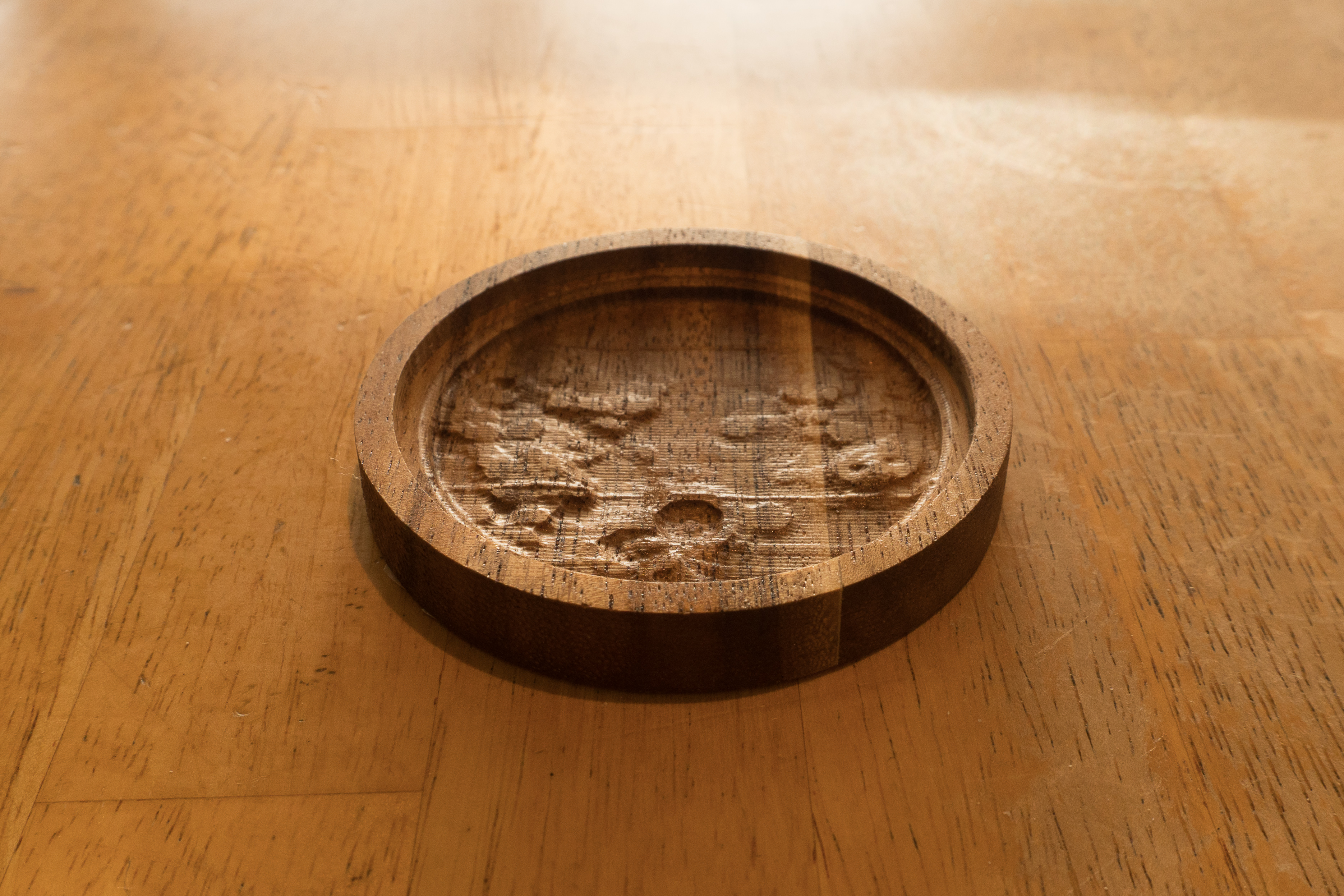
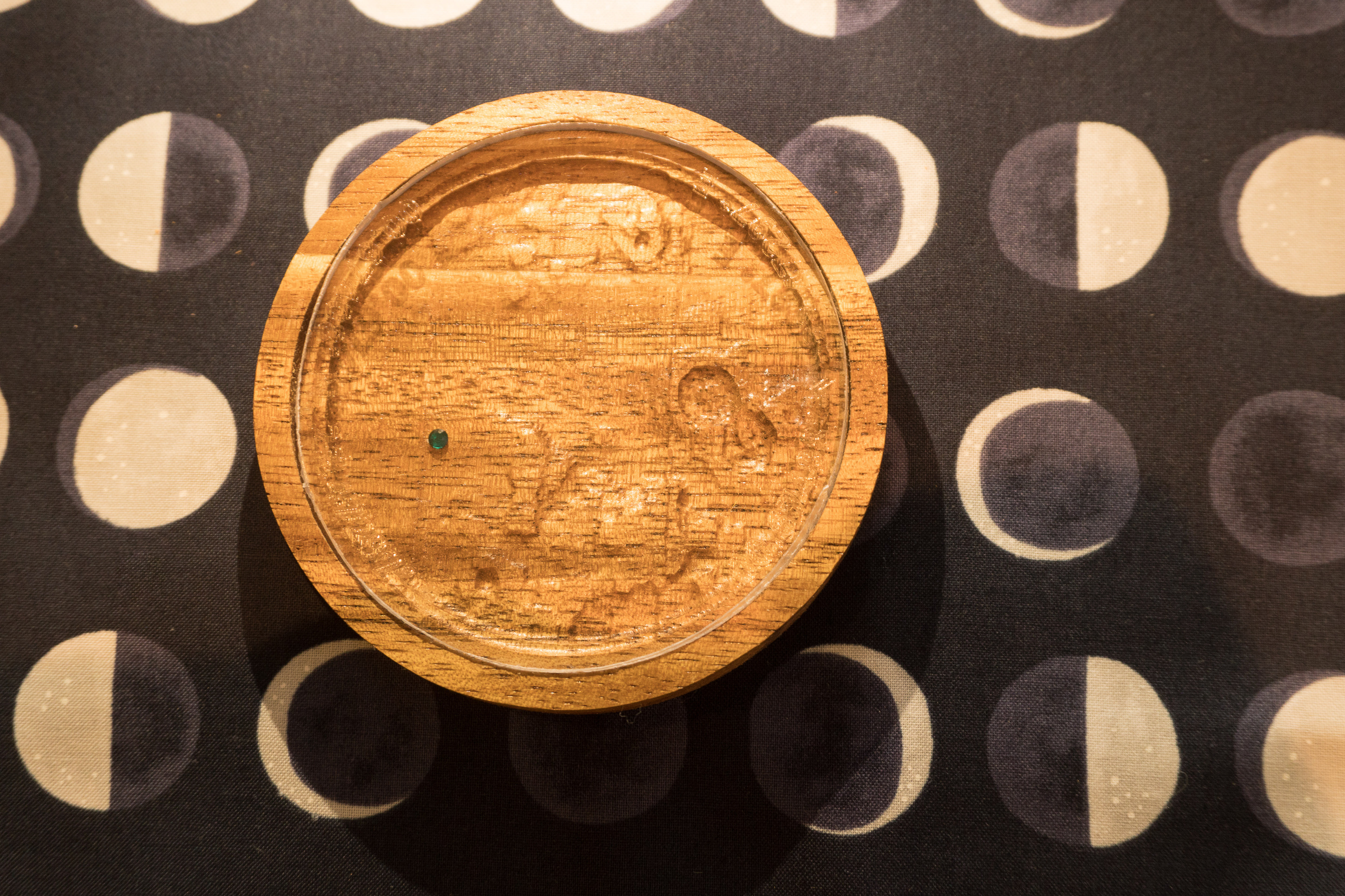
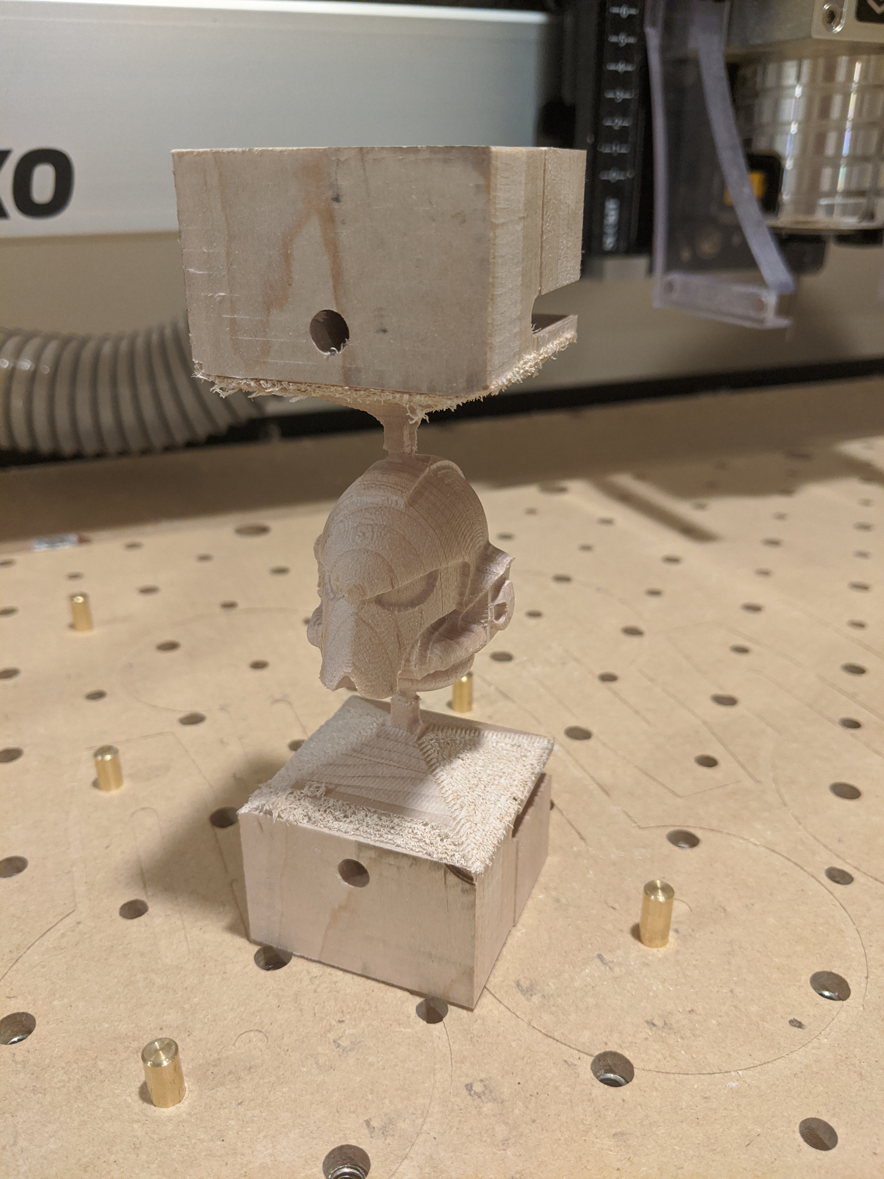
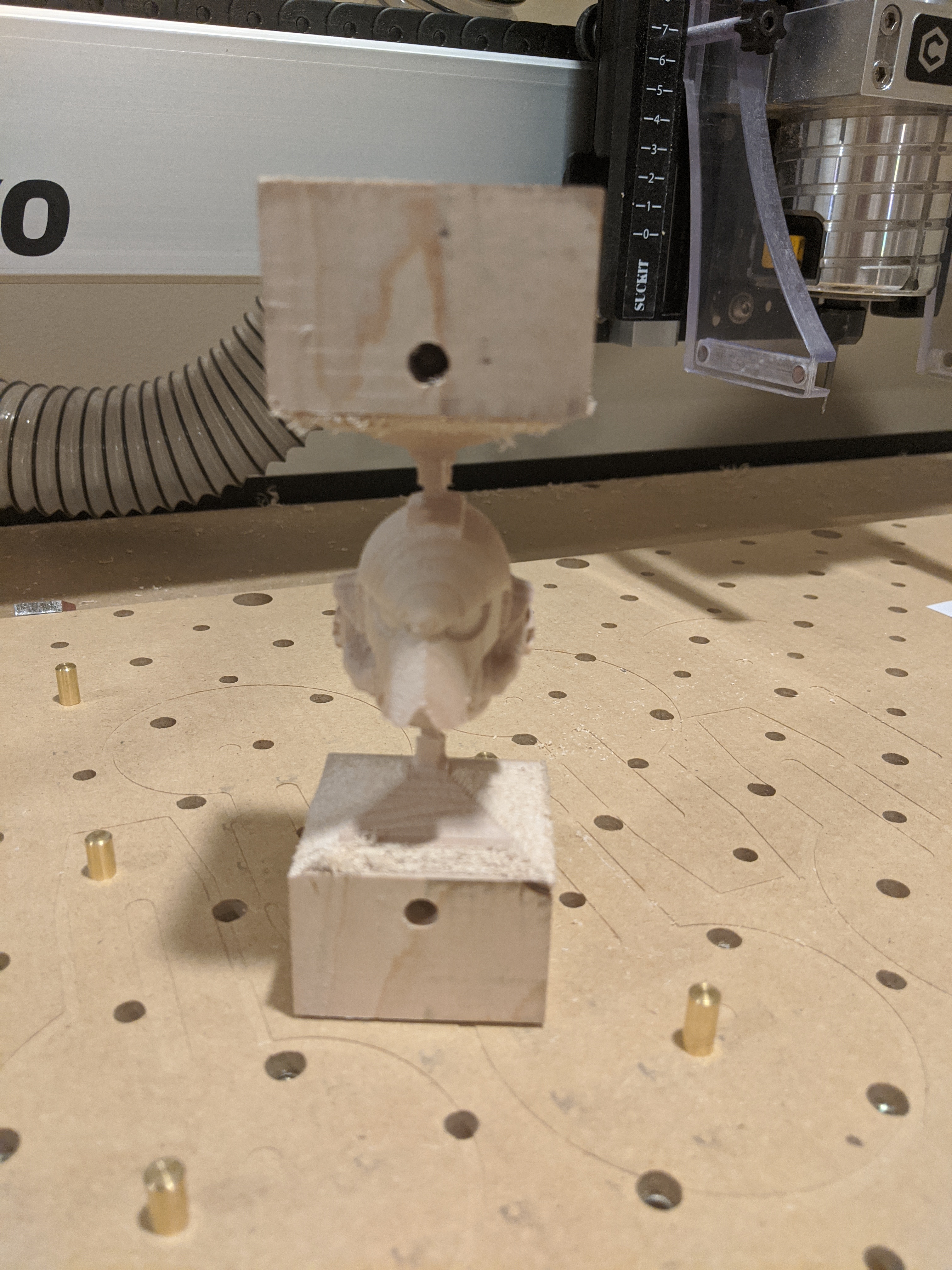
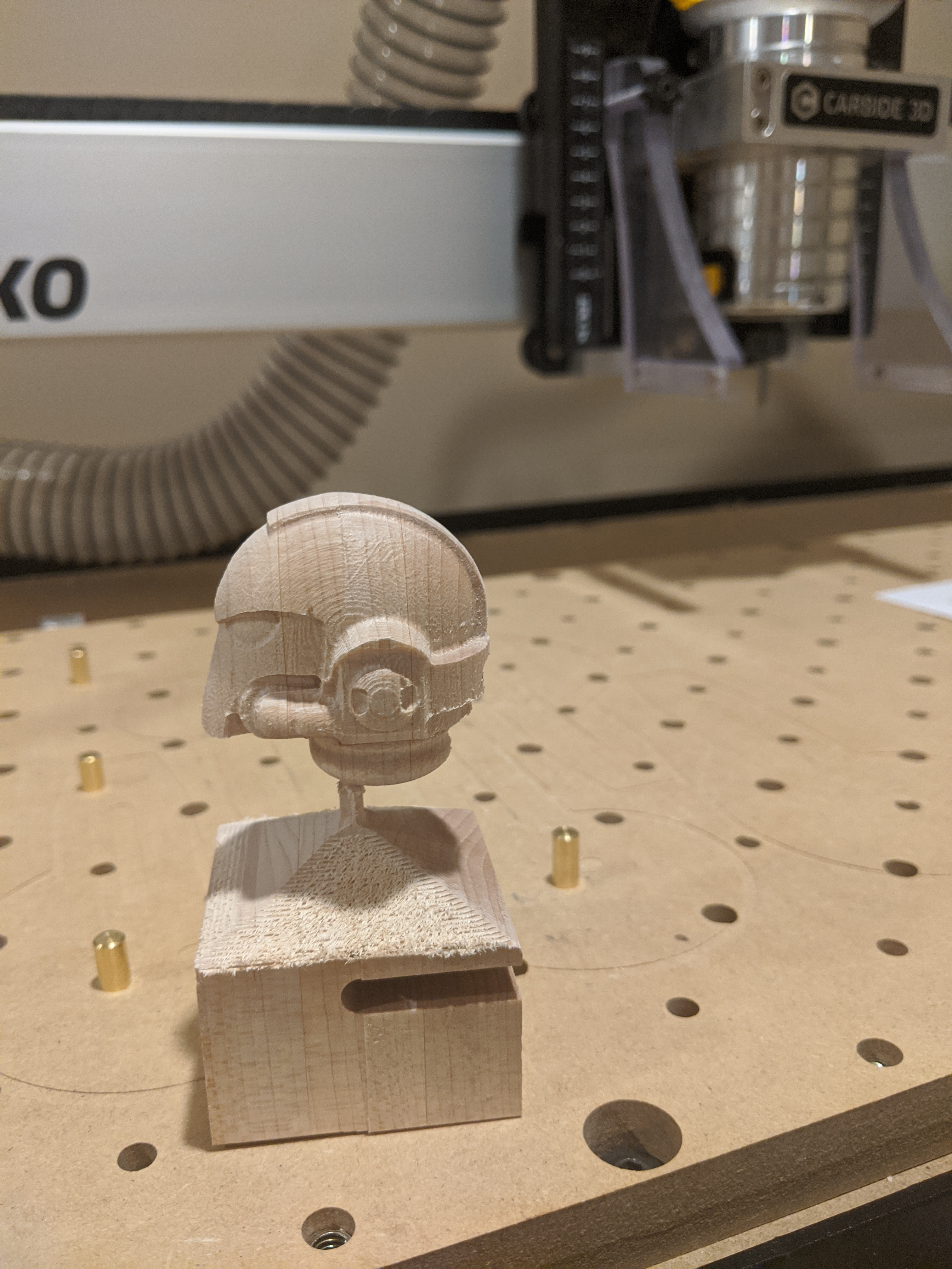
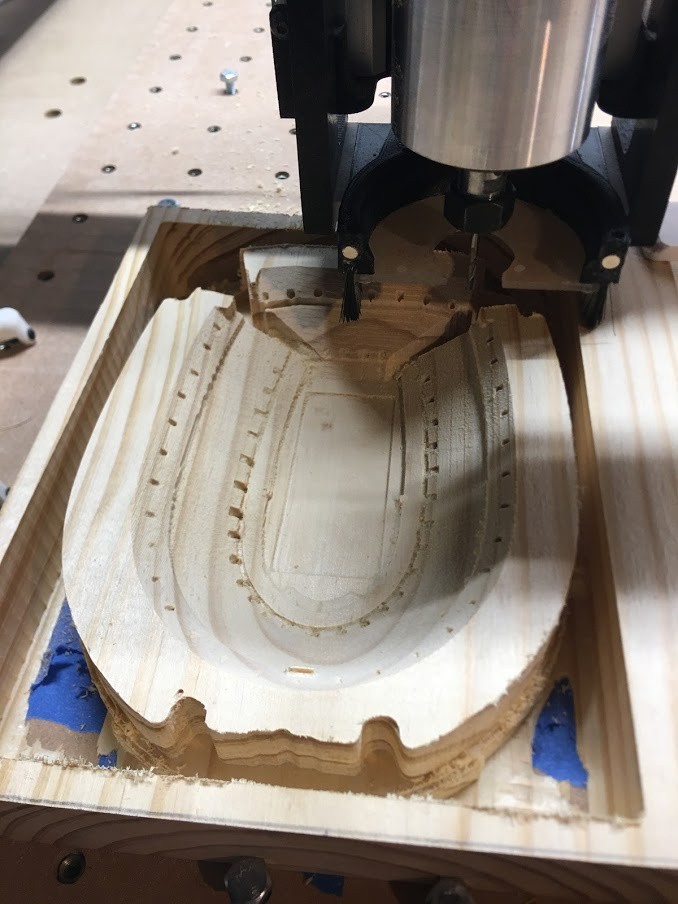
Then the 3D finish

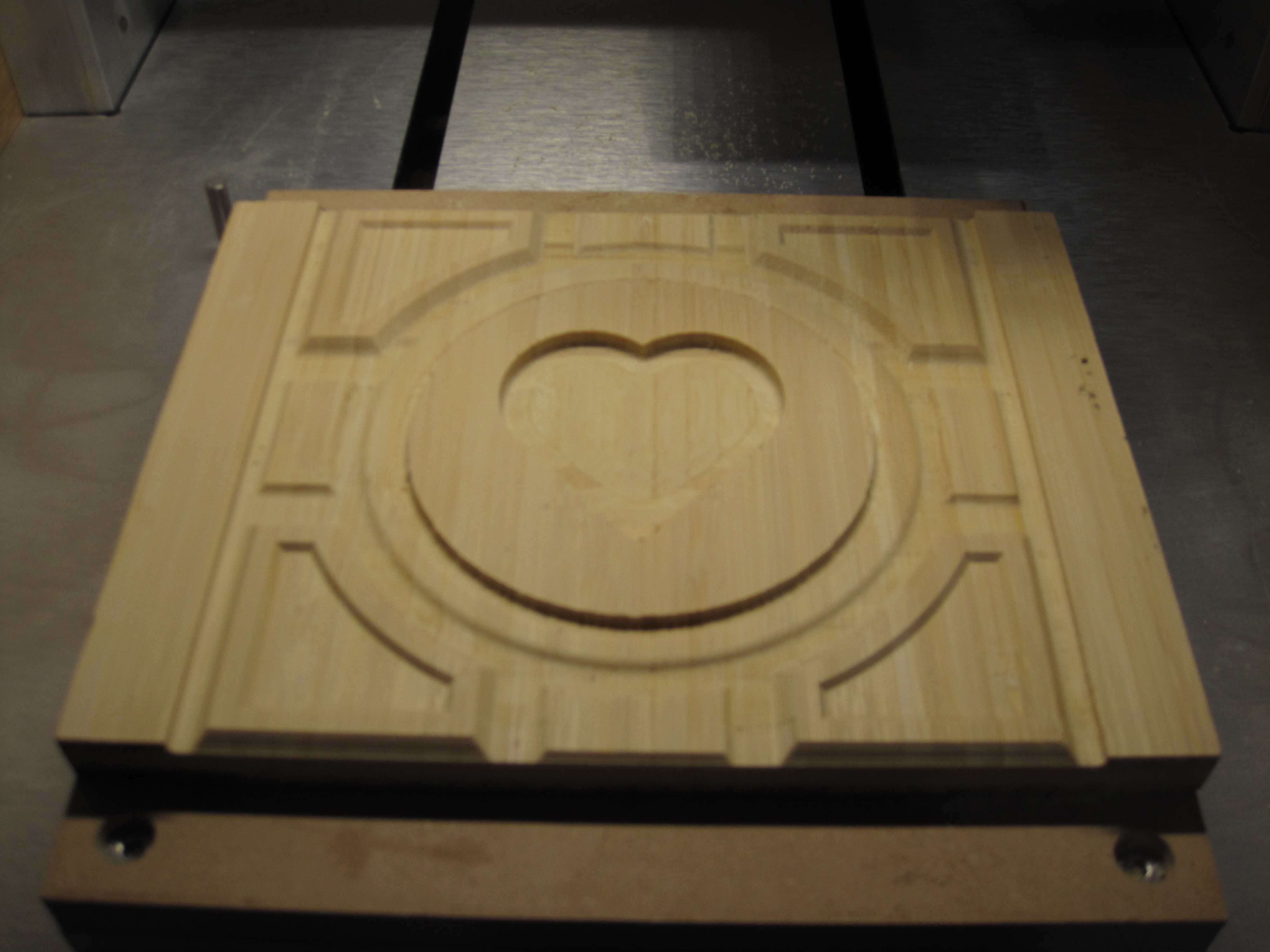
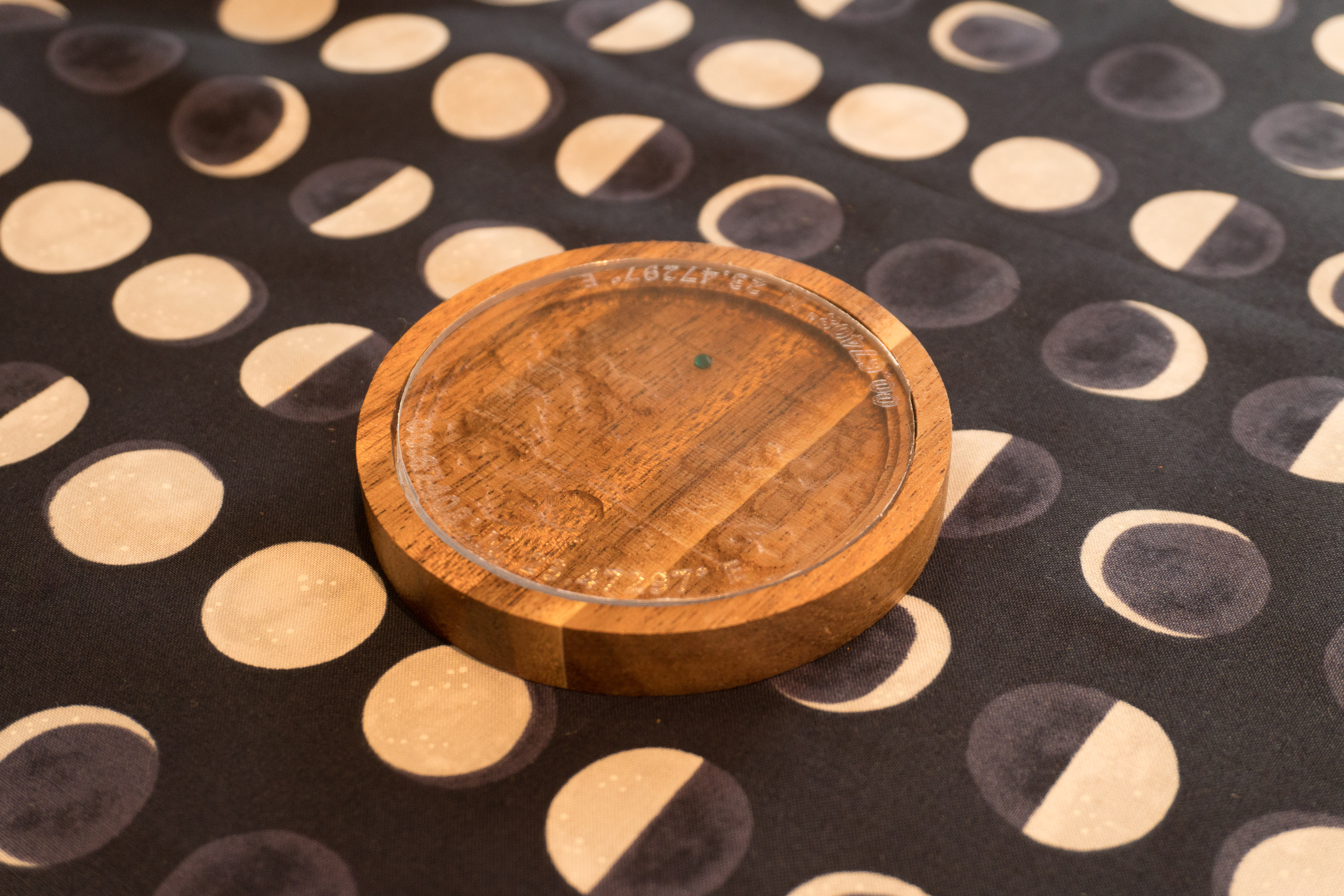
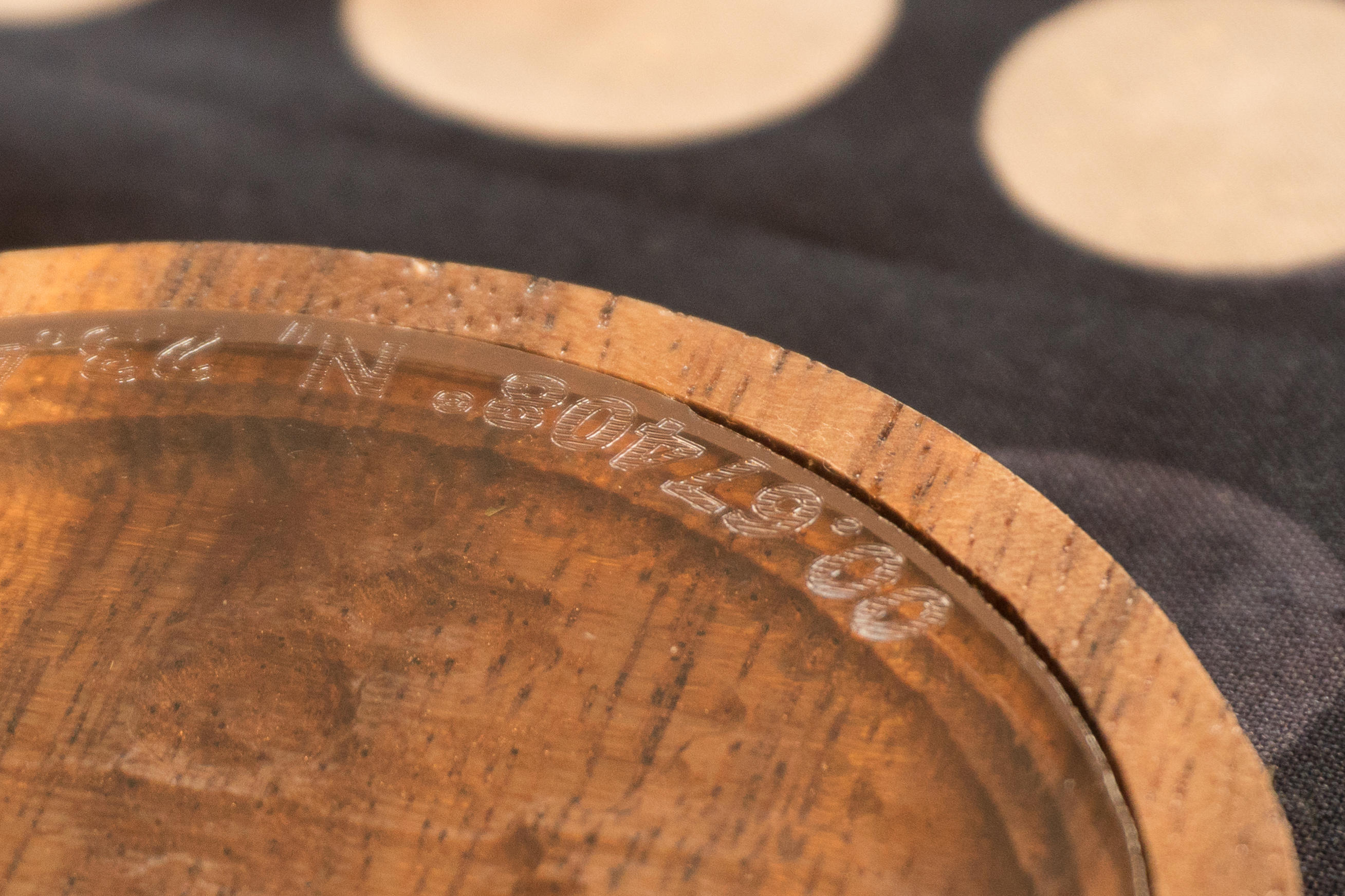
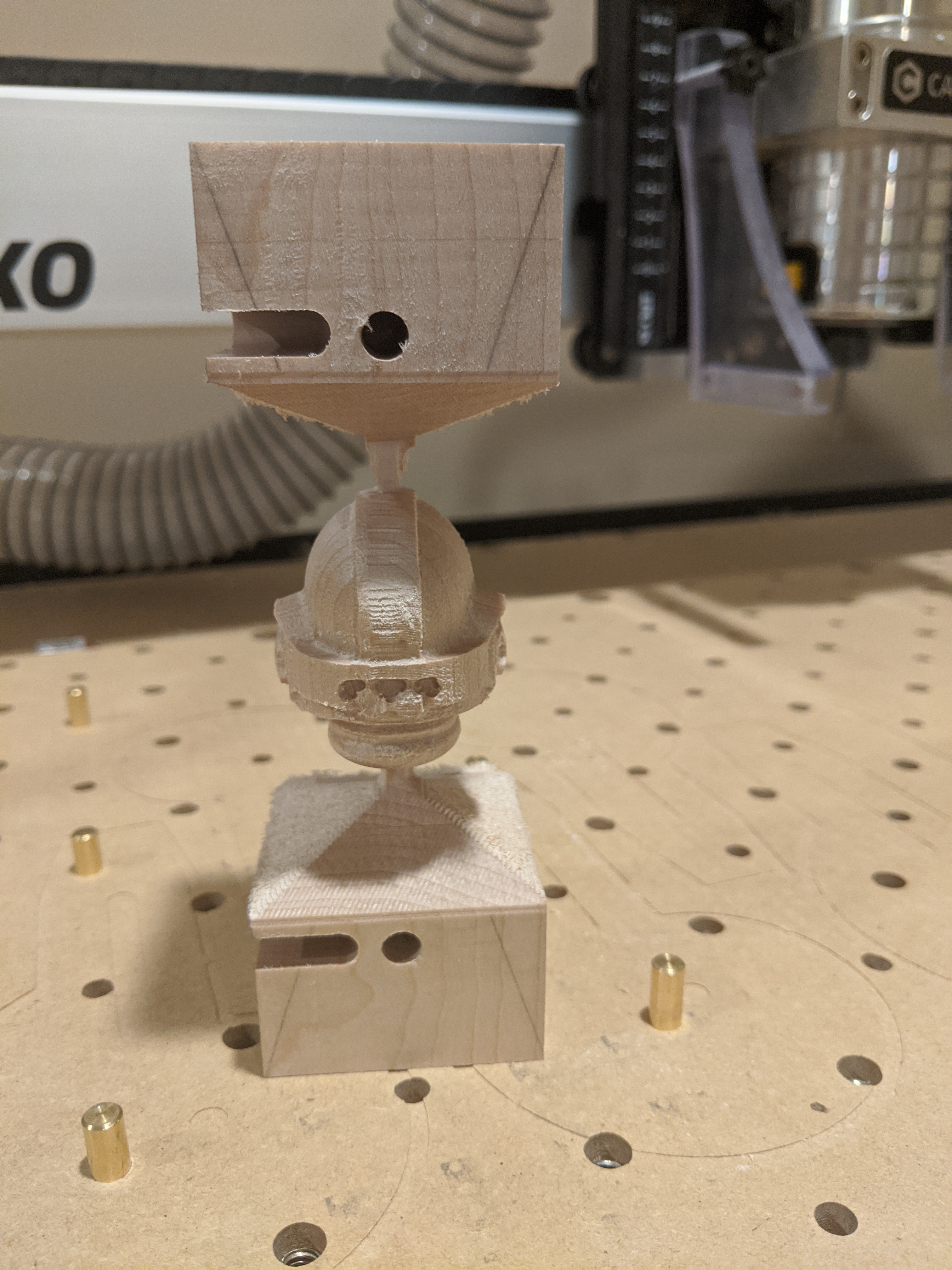
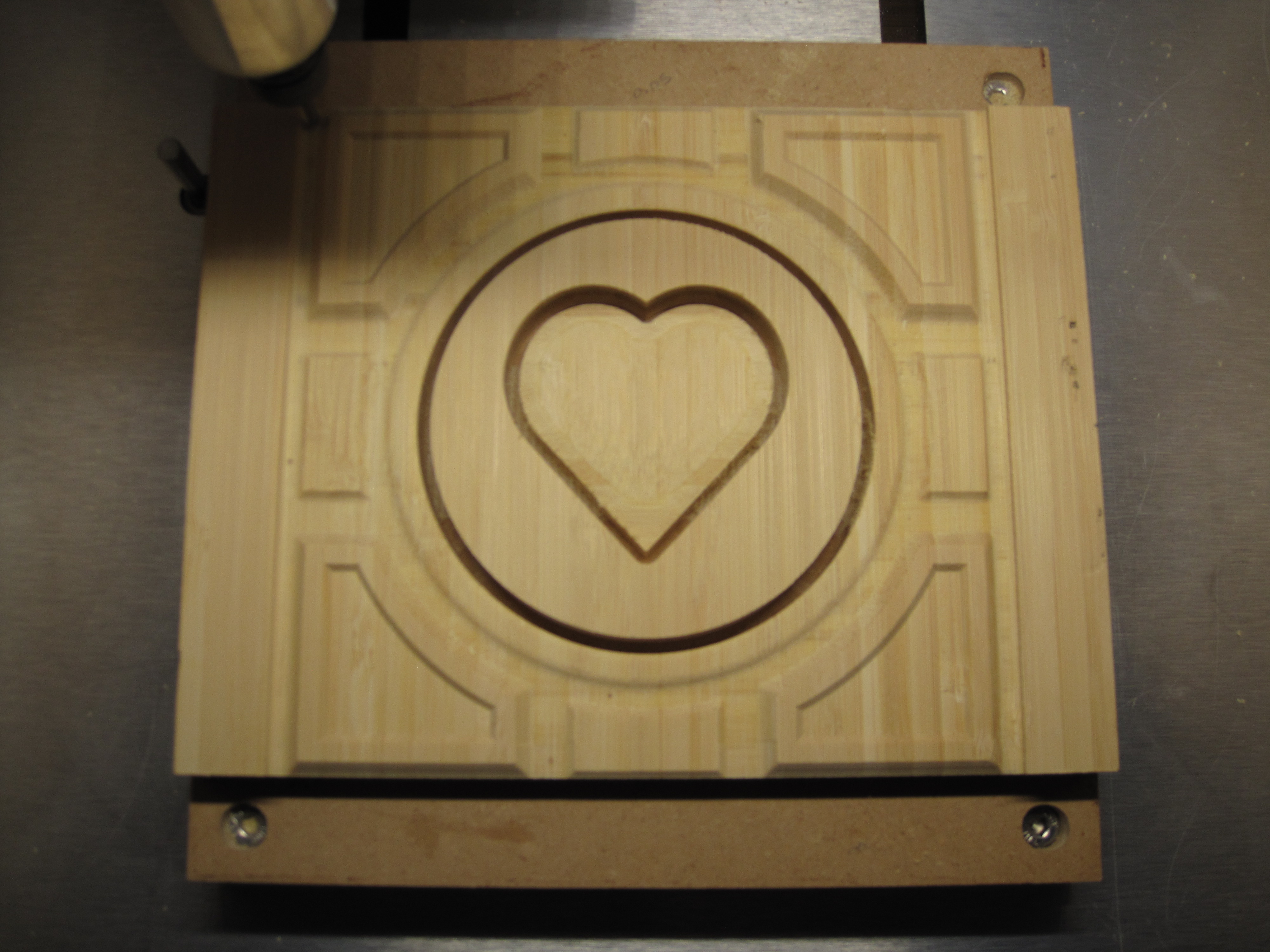
Then cutting out the center circle which I plan on replacing with lexan.

Then cutting out the square

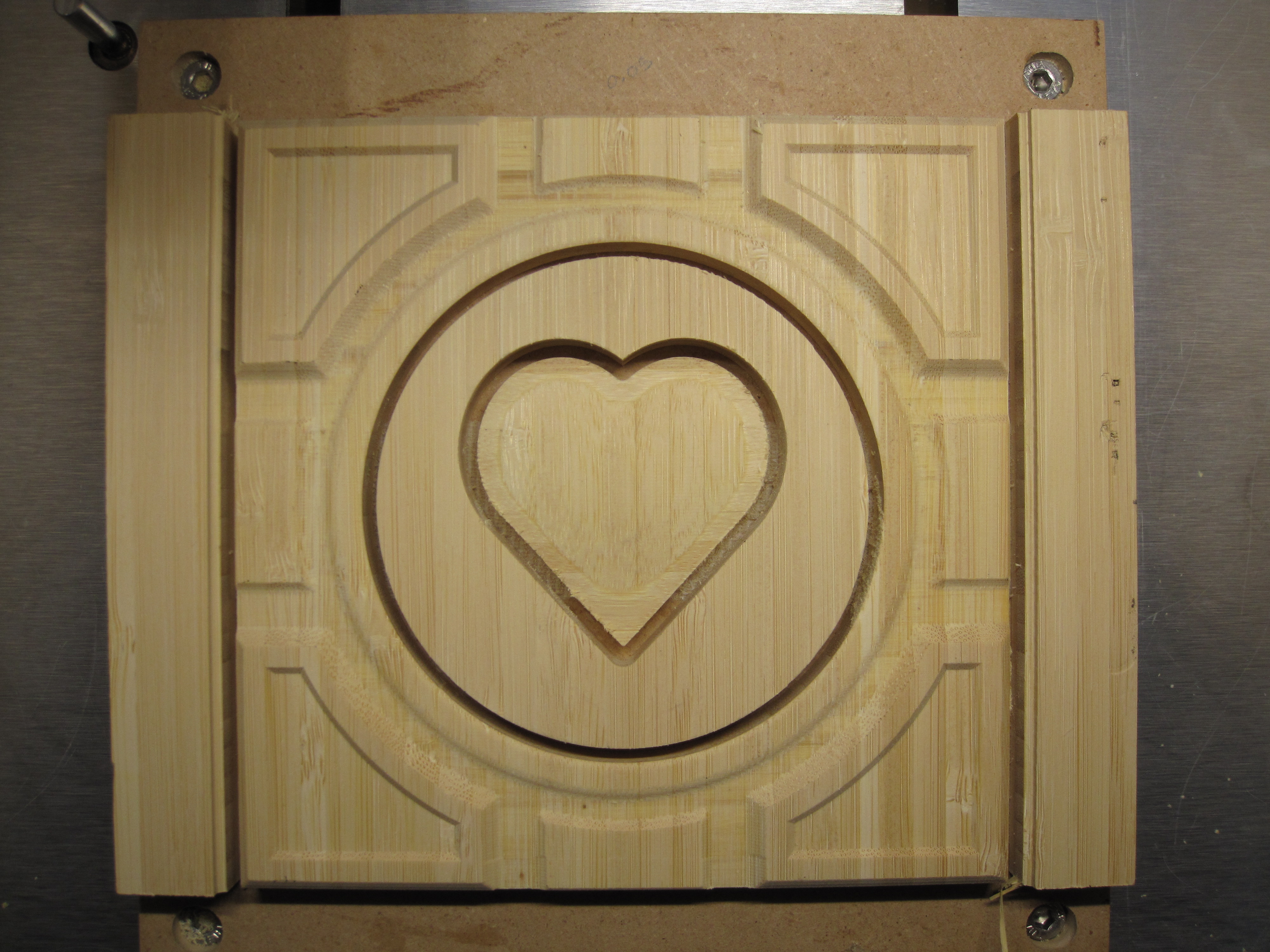
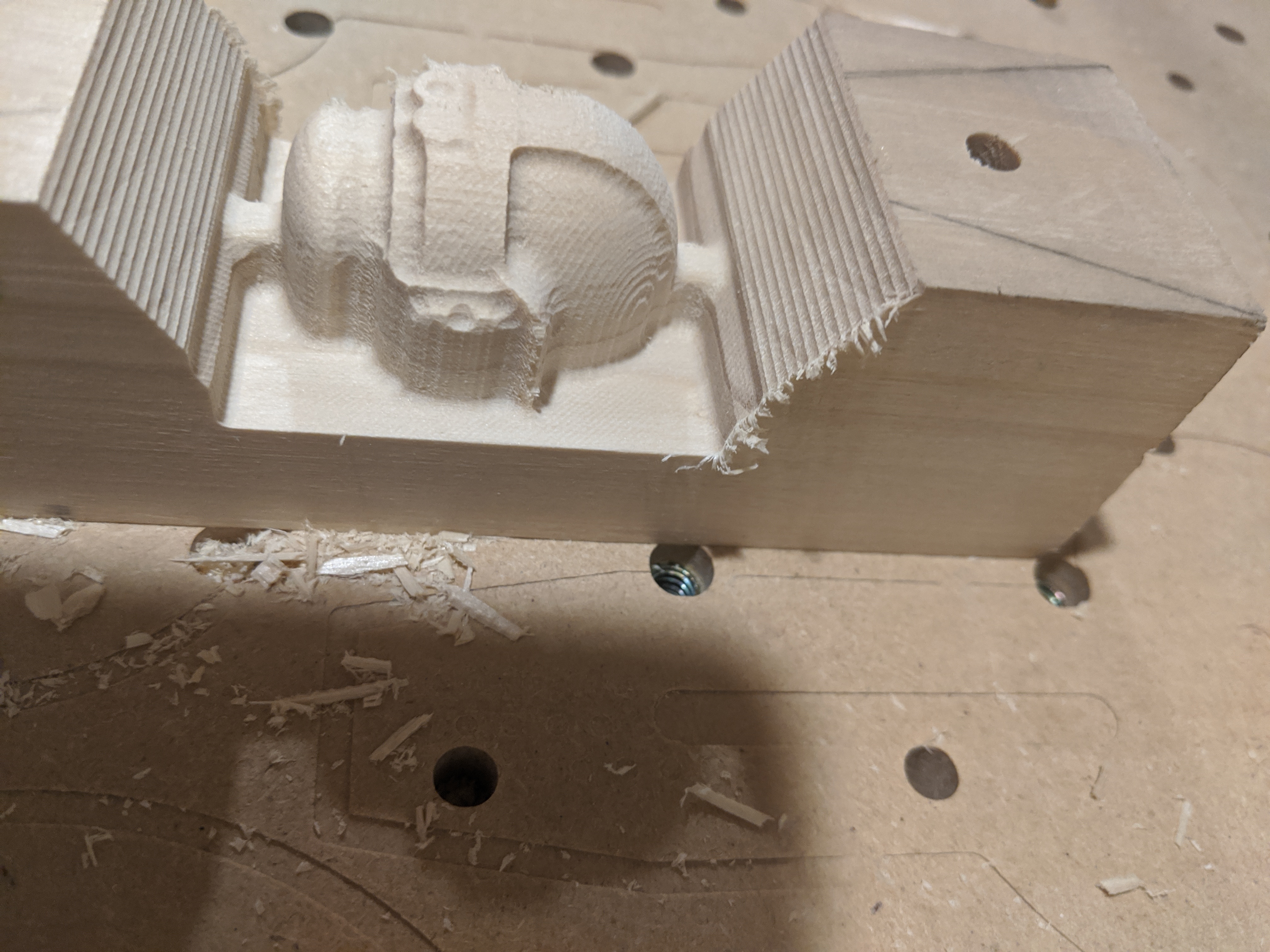
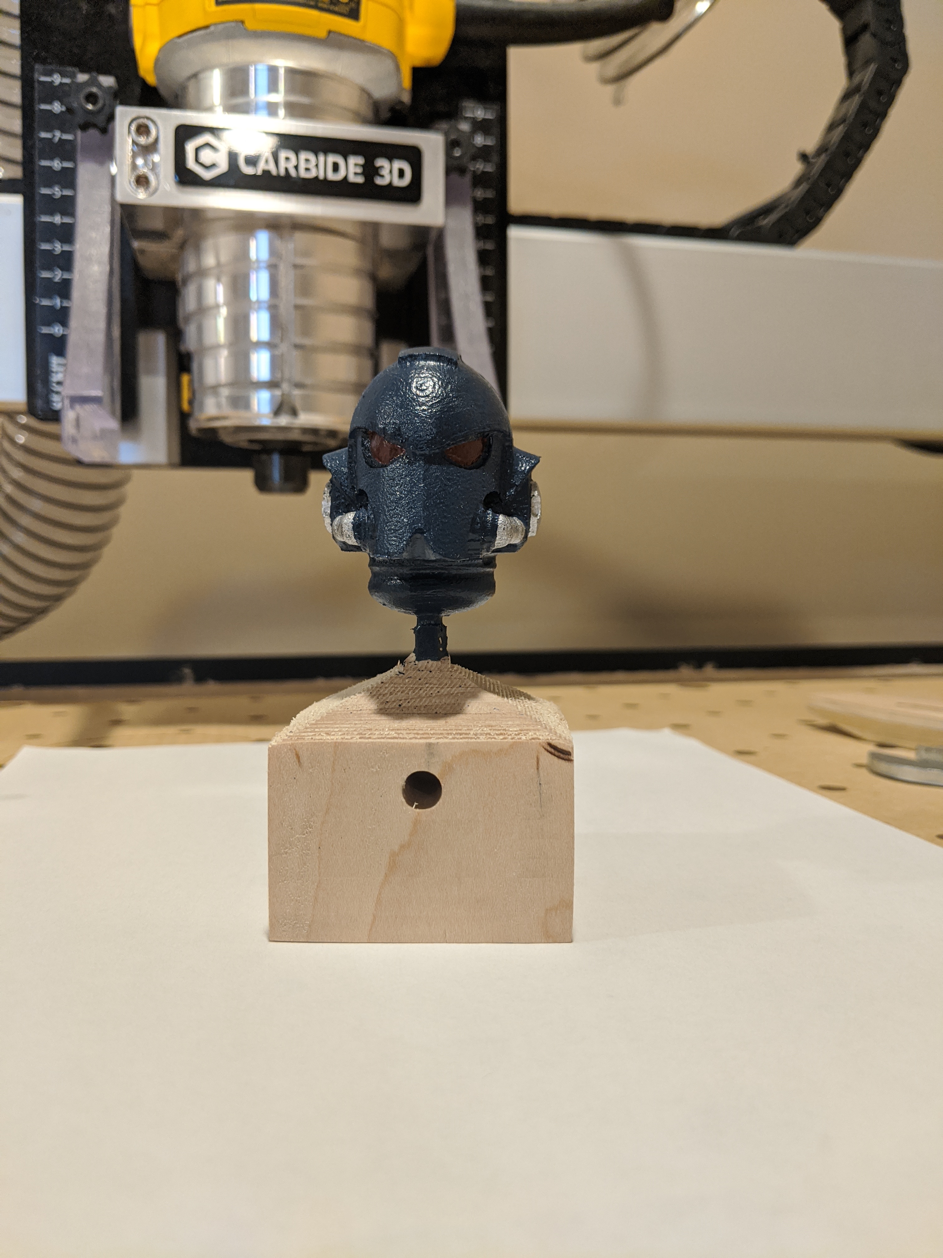
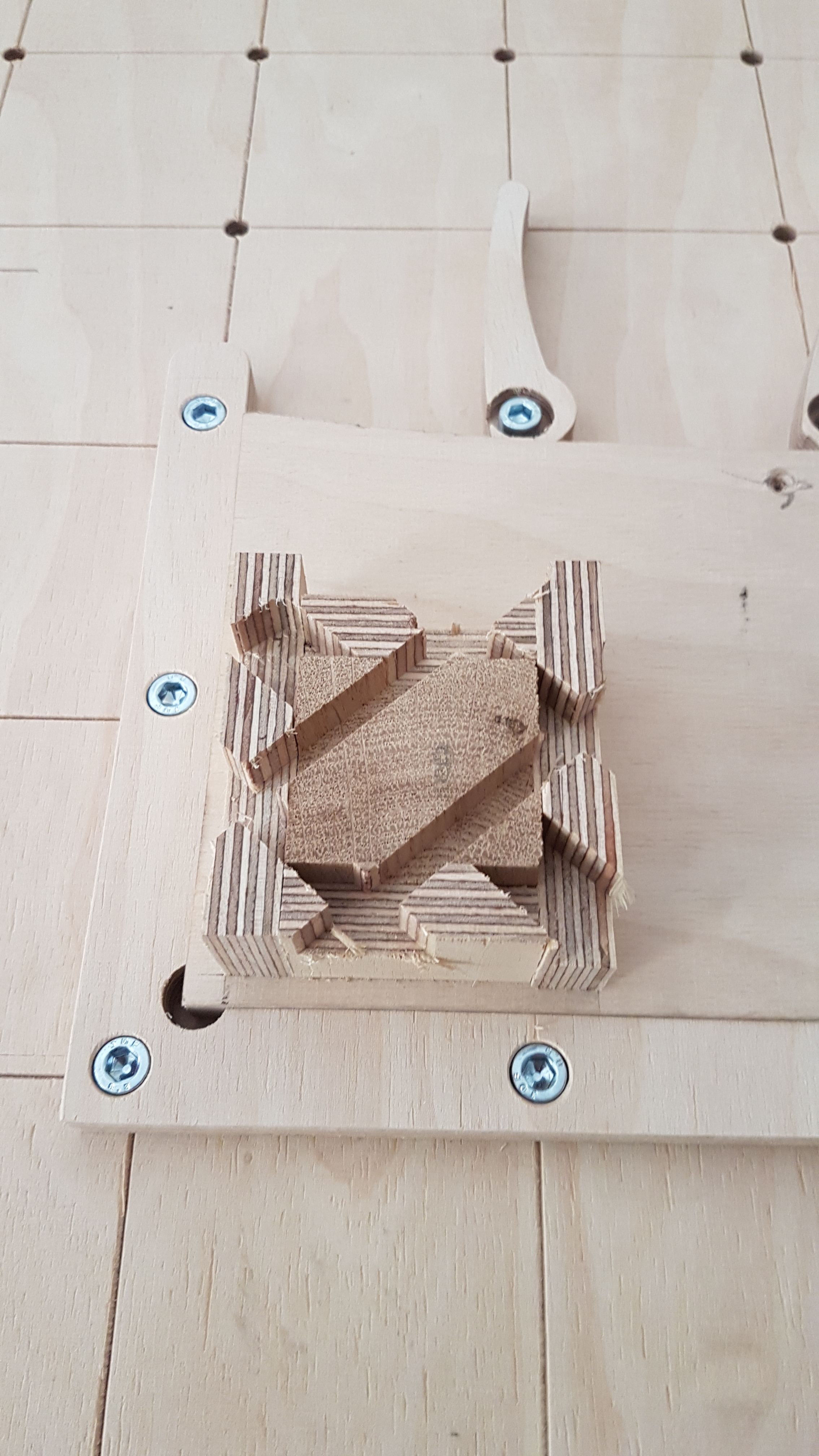
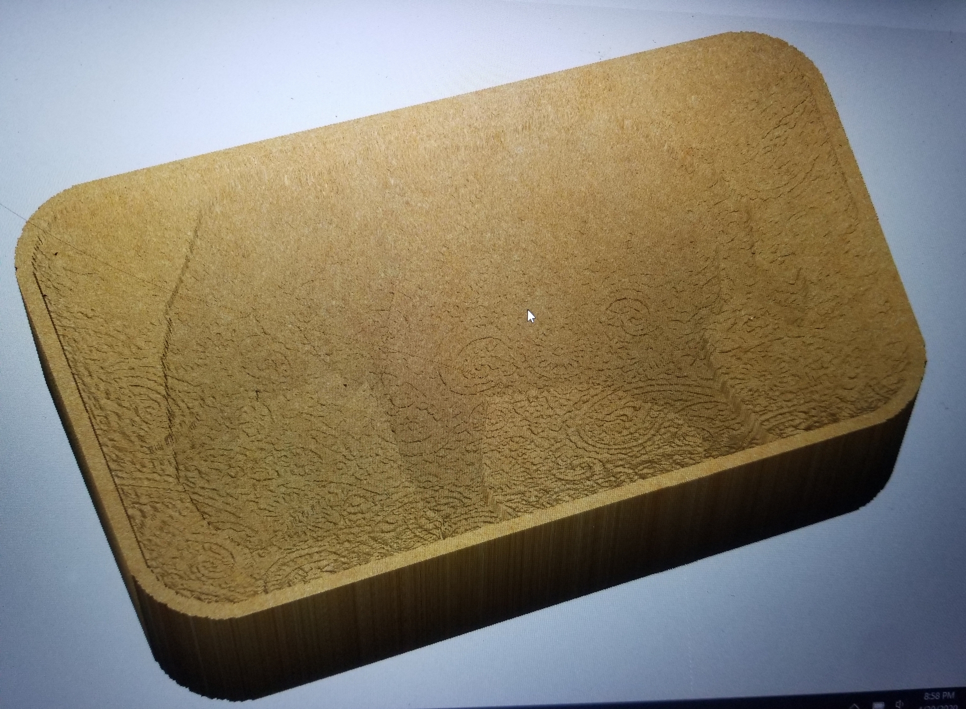
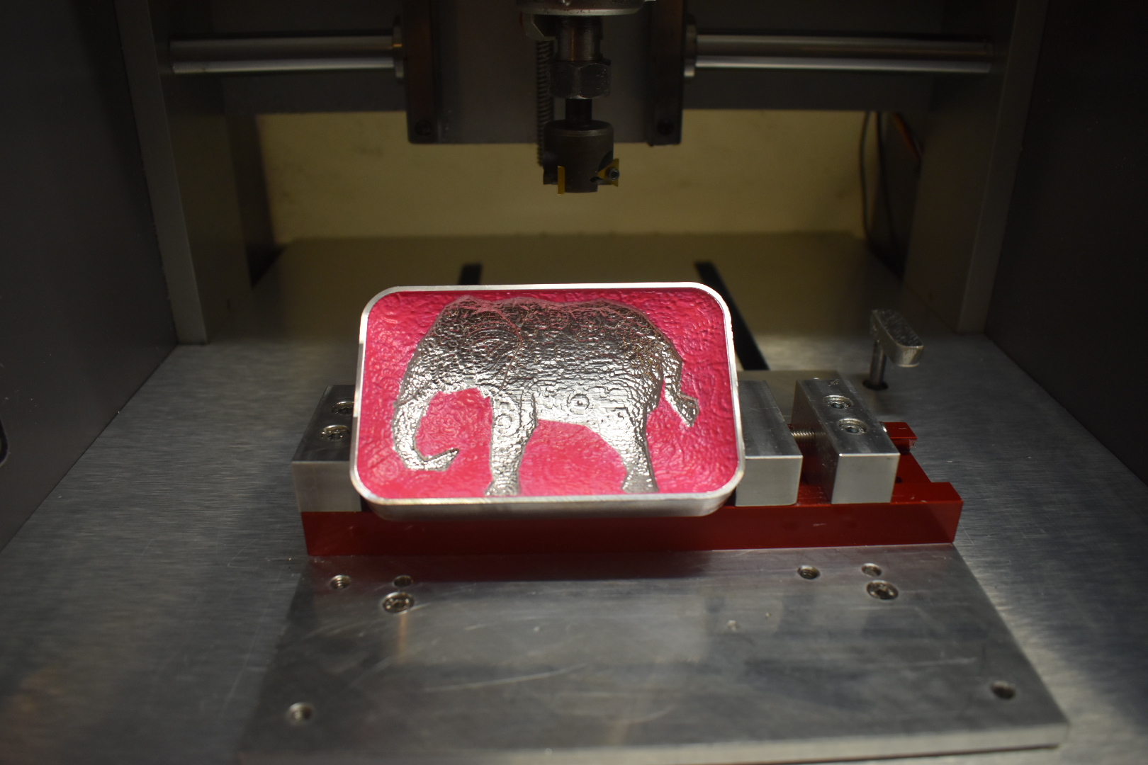
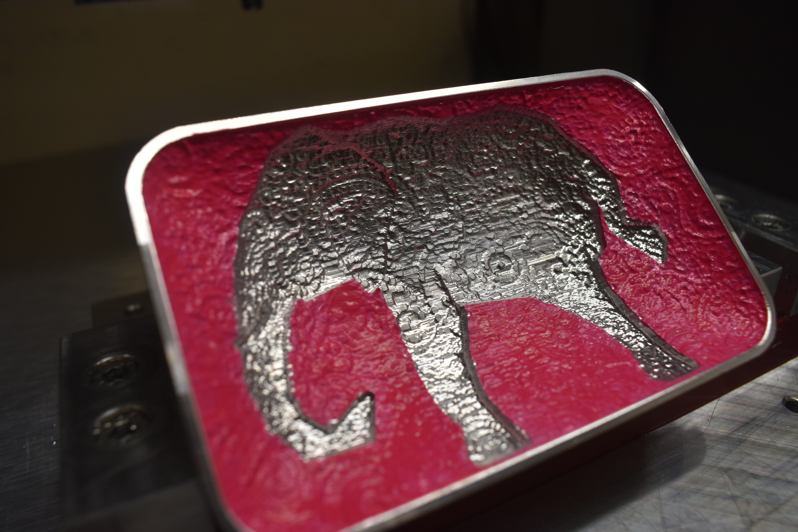
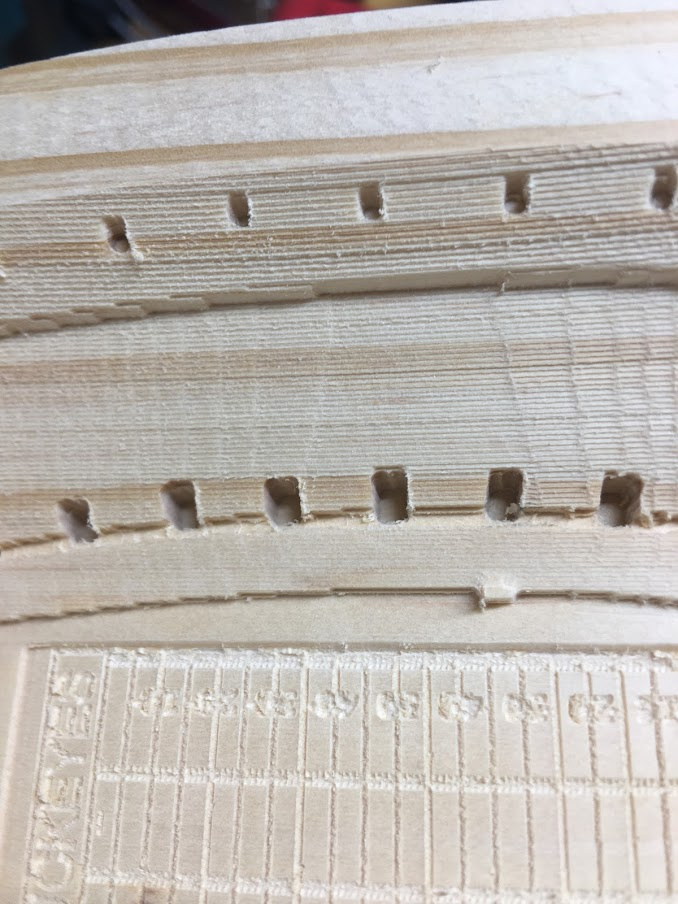
Notice the difference between the (sharp-crisp) v-carve in the corners to the (soft-smooth) round and angle 3D modeled objects. I am very impressed with Carbide 3D’s software.

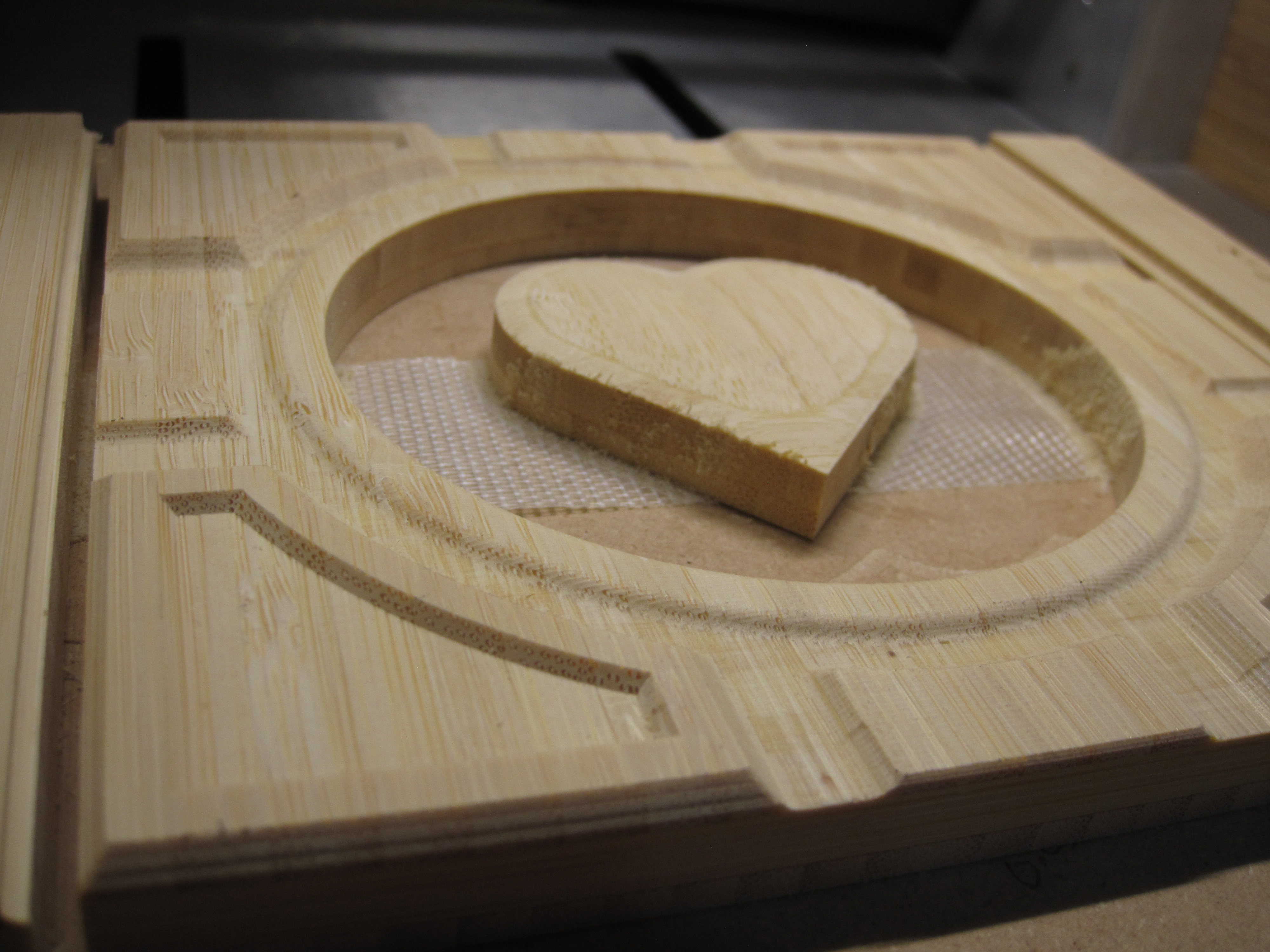
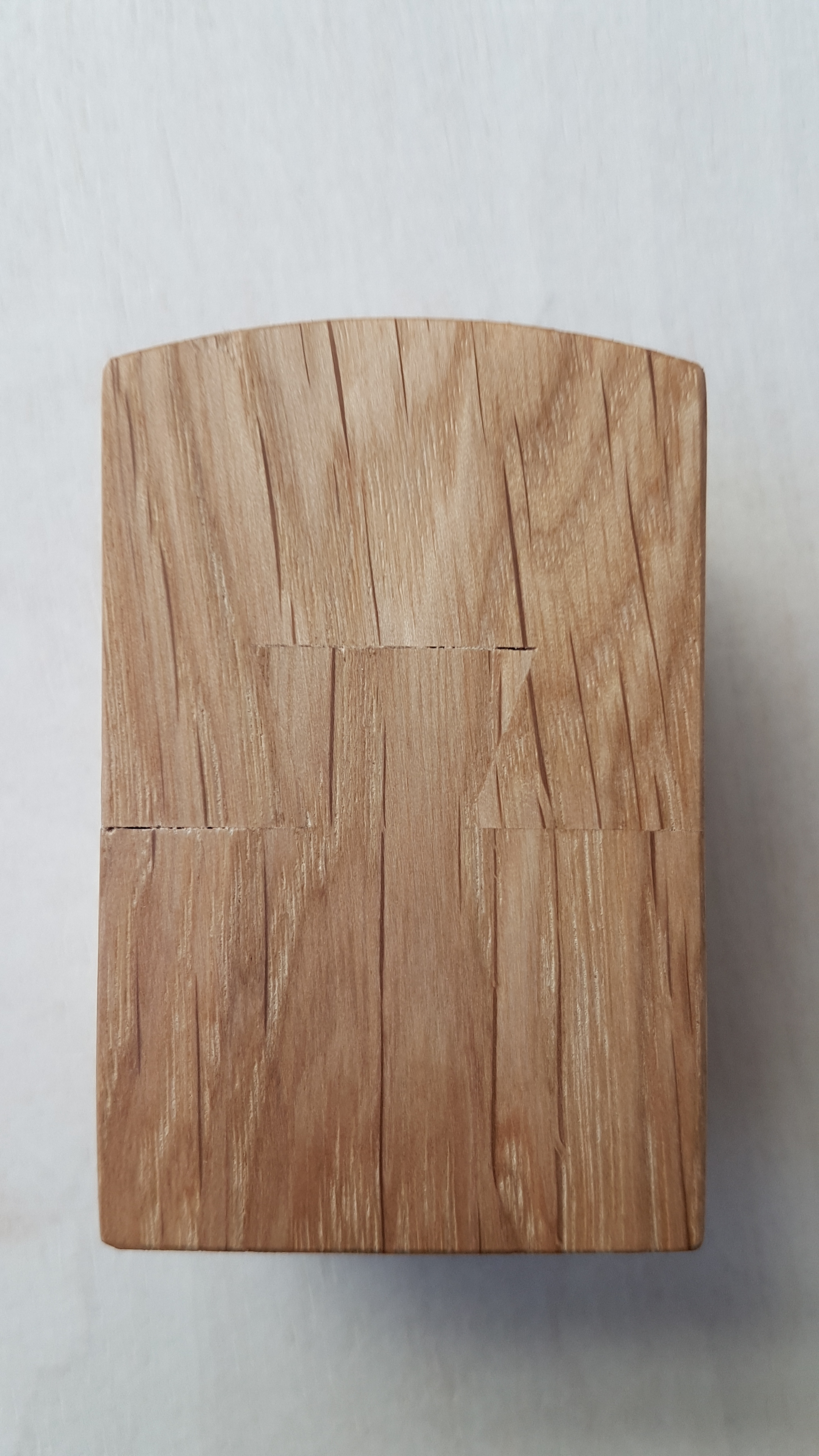
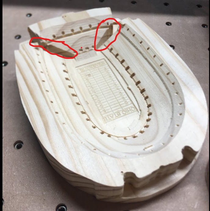
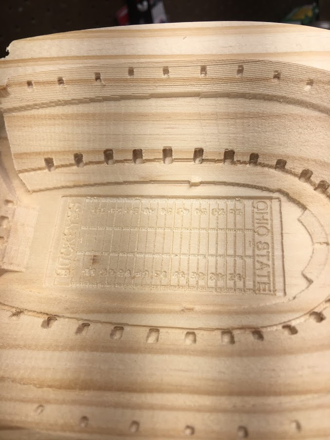
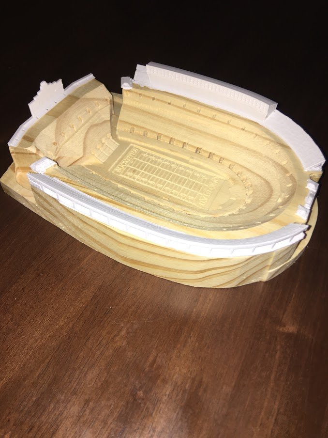
And after some cleanup, here is the result. Now I just need to repeat 5 more times for the other sides.

The Vcarve used a 90 degree v bit, but everything else done with the 1/8 end, 1/8 ball, using the default feeds and speeds built into Carbide Create.

Cube.c2d (1.9 MB)

8 Likes

Was the grain matching of the heart a necessary design element?

Did you consider just cutting the circle out and using the blank for some other project and making the heart out of a contrasting piece of wood?

1 Like

The real answer is that the design was secondary to the learning experience. I was wanting to learn the 3D modeling and how the add and subtract worked.

However, if you look close I almost pulled off something neat. Notice you can see an outline within the heart. That wasn’t machined, that is where the bamboo grain alternates in the wood I am using. The outer edges of the heart has horizontal grain while the inside has vertical. If I were to start over I would adjust the model to make everything that is raised fall into that horizontal grain and everything that is lowered go down into the vertical grain. I missed it by less than 1/32.

2 Likes

Is that Arcana io from Dota! Can’t wait to see it finished!

1 Like

Or is it a companion cube from portal? WE MUST KNOW THE TRUTH!

Looks great by the way!

CompanionCube

2 Likes

Hi,
Today I redid a little project.
I wanted to assemble two dovetail woods, and test the writing on 3d with CC.
Capture

I’m still missing some precision on the dovetails, my woods were not square.

But the curvature and the handwriting comes out well.
It is not possible to make a contour (shape or writing) on CC?

I made a template so I could machine them and avoid wood splinters.

bombe ecriture.c2d (170.2 KB)

4 Likes

I believe you want to see the 3D modeling features in Pro mode which has a free 1 yr. license available:

Companion cube was the intent, but it’s interesting that another game (DOTA) has almost the exact same object. And when you consider that my plan was to add lights inside, it may end up looking more like the DOTA object than the Portal object when I am finished.

3 Likes

Oh wow, I really like this! I’ll have to make one for my mom (cardiac nurse).

I wish I could enter but I’ve got larger woodworking projects to accomplish currently.

Oh wow, I really like this! I’ll have to make one for my mom (cardiac nurse).

I wish I could enter but I’ve got larger woodworking projects to accomplish currentl

Isn’t it awesome what can be done with CC Pro! With all the credit due to the Vectric and Fusion users out there, I’m really impressed with the entries this time around. Great call on the challenge idea Carbide Overlords!

1 Like

Okay, the “Text on a Curve” got my brain going… I did have to import a graphic I made in photoshop, but it was just so the curve would be what I wanted. Here is what I ended up with…

Using this graphic as an imported (model?) no imported image.

TextOnCurve.c2d (783.1 KB)

3 Likes

Bump. Finish line ahead, come on let’s see some last minute entries !

2 Likes

Boom. Topographic carving of the Hawaiian islands, complete with ocean floor though the resin is a bit too opaque to see. Initial coat of epoxy with mixed blue mica pigment powder, followed by 1//8" of clear, and a finish coat of Total Boat Tabletop epoxy. Some small mistakes were made, but came out well enough that I think I’ll try again with other islands. This one will get thinned out and turned into a drink coaster.

14 Likes

My girlfriend has been making soap as a hobby during these tough times and she loved the idea of a custom soapholder.

Time synced with the final assembly of the upgraded Nomad and a piece of 6061 2.75x4.5x1 billet was thrown into the mix. Now im a total CC Pro newb but came out with pretty decent results. Took a 3d elephant from Thingiverse and converted it on the side. Played around with a simple box and added a very subtle paisley texture on curve action. Hindsight, shoulda had a 1/32 endmill on hand, but, its character.

Nomad with 500w brushless Makita
Vise and face with 1" triple insert face mill
Mdf table flippy flop with a glue/tape setup
0.250 Single flute 3d roughing
0.125 Double ball 3d finish on zero
0.0625 Double ball 3d finish on zero
0.0625 Double ball 3d finish on 90 degree
0.250 Single contour
Flip and 1" triple facer
Pink enamel paint applied by hand.

elephant soap dish.c2d (1.8 MB)

Part is straight off the machine without any additional post processing. All speeds and feeds were CC defaults for the Shapeoko + 150-200%.

7 Likes

OSU (American) Football Stadium:


Hopefully I’m not too late to the party!

I’ve had a really cool .stl file (Link) in my pocket that I have wanted to make for a while. I could have 3D printed the whole thing…but where’s the fun in that!? Plus, I figured this would make a great Father’s Day present (since my dad loves the Ohio State Buckeyes) on top of just entering the contest. I used good ole Southern Yellow Pine since I already had it on hand :stuck_out_tongue:

So there was a ton of extra detail in this STL file that I knew I did not want to tackle in CAM (many-sided machine job, lots of fixturing, etc). I took the original file and chopped off the top part where there was a ton of detail (press box, upper stands, scoreboard). This gave me a simplified version to work from:

I used @fenrus STL converter and took only the top image of my simplified STL:

So off I went to chop up a little piece of cheap pine (and surfaced one side to be able to use tape/superglue):

First roughing pass was just the good ole 201 bit:

The second pass I did was to use at FLAT 1/16 inch bit (didn’t have a ballnose yet, and the ones I ordered wouldn’t come in time for the contest). This actually had really a cool effect that I liked, making there seem to be rows in the stands of the stadium! :


I was going to have a ¼” ballnose bit go over with another finishing pass, but I decided not to (I liked the lines and didn’t want to gamble with the chunky 1/4 inch bit.

I ran a 1/8” bit to clean up the small gaps at the south (“BUCKEYES”) side of the stadium. This took a couple of tries to get the nodes close enough so that the bit would clean up everything (helped clear out the deep/narrow places circled in red):


From there, I thought the model needed a little something extra to make it stand out more. I thought V-carving would make a great addition by detailing the football field. So next, I ran the vcarve for engraving the field. I used a free football field svg from Wikipedia and then added in my custom football team name to the endzones. The result gave away that I was using cheap pine, as the engraving didn’t cut super cleanly. But, for this contest it’ll have to do:


Zeroing the Vcarve was tricky, since CC thought I wanted to Vcarve on the orignal top surface of the piece, sooo I had to improvise with a new Z zero:

Then a quick cutout with the #201 and after some tiny cleanup:

Bonus: I decided to 3D print the top part of the STL that I had originally cut off in software. I’ll probably paint it eventually to better resemble the ‘Shoe but I’m making due for now:

Real life pic (with a few people in the stands)


Go Bucks!
Kyle

File:Ohio Stadium_Bottom part.c2d (875.2 KB)

P.S. Right now I’m leaving this as is and will just spray enamel on it but…I’m open to suggestions on other options to finish this…paint? A light stain? I don’t want to lose any of the features, and don’t want it to look cheaply painted :grinning: loving this community to share our cool stuff!

13 Likes

I’ve had my Shapeoko for a while and mostly lurked but thought with the global situation it’d be a good chance to revisit Carbide Create so I created a coaster of the Apollo 11 landing site using some scrap Acacia and acrylic.


I used height data from the Lunar Reconnaissance Orbiter Camera (http://lroc.sese.asu.edu/data/) and navigated around to the find the Apollo 11 landed but zoomed out enough to include different interesting features since the landing site was, for good reason, relatively flat.

Design

For the design, I made 3 separate Carbide Create files. I could’ve used one but found it easier to keep the parts of the project compartmentalized.

I first used the design environment to draw 3 circles all aligned on the center of the stock. I then switched to the modeling environment extruded the inner and outer circle using the maximum. I selected the inner circle and imported the Moon height map then used a square the size of the stock along with the outside parameter of the coaster to zero out the portion of the moon that overflowed by setting the height to zero and using the minimum function. Set my stock zero to the bottom left and z-zero to the stock height so that as material was removed, I’d be able to still reliably use the touch probe.

1.1 – 3D Rough and Contour

I used the 3d rough and then followed it up with 2d contour to remove the 0.5mm of remaining stock from the top of the inner and outer ring left by the roughing tool path. One little hiccup I ran into was that you can’t contour down to a surface so I had to do a bit of math to subtract to top of my rings from the top of my stock. Left the feed and speed for most operations as defaults because they’re all quite conservative. In the future I’d speed the roughing one up a bit.

201 - .25 Flat Endmill
Stepover: 3.175mm
Depth: 1mm
Feed: 1540mm
RPM: 18000

1.2 – 3D Finish Lunar Surface

Included in the CC file there’s also a vertical pass but I was happy enough with the result of the single horizonal pass I didn’t bother doing it.

101 – 0.125 Ball Endmill
Stepover: 0.318 mm
Feed: 1540mm
RPM: 27000

1.3 – Cut Out

201 - .25 Flat Endmill
Depth: 1mm
Feed: 2286mm
RPM: 27000

2.1 – Bottom v-carve Apollo 11

If I were to make a bunch of these, I’d make a jig to hold the upside down but since this is a one-off for now, I just used a compass to mark center and clamped it down.


60 degree v-cutter
900mm
RPM: 18000

The goal was to do as much as possible in Carbide Create but making text follow a path isn’t something it’s good at. Instead I used Inkscape to draw a circle slightly smaller than the acrylic insert and made the text follow that path. After tweaking the spacing between letters and the sizing, I converted the letters to paths and imported it into CC.

3.1 – Diamond Engrave Lunar Coordinates

Added a new tool to the CC library with a 0.1mm diameter. For this operation I use two paths, a 3D finish path for the letter’s fill and contour to add a sharper definition to the outside lines.
image


Depth: 1mm
Stepover: 0.381mm
Feed: 1600mm
RPM: 0

3.2 – Cut Out

No tabs on this cut but in addition to the clamps, I stuck the middle of what would be the insert down with double-sided tape. Something went wrong and the cut isn’t quite as clean as I’d hoped.

.125 1 Flute Endmill
Depth: 1mm
Feed: 1146 mm
RPM: 21000

Finishing:

I did a light sanding with 200 grit sandpaper the used spray poly as the finish. For the bottom, I sprayed a couple coats of poly first to reduce the paint bleed and make it easier to wipe any mistakes I made off. Next time, I’ll probably experiment with masking since everyone carving signs makes it look easy. Finally added a little plastic gem to my best guess of where the landing site is and fit the acrylic in.

Overall, I’m pretty happy with how it turned out. There are a couple ridges that I’m not sure if they’re an artifact of the 3D finishing or if it’s time to tune my machine again but requires more investigation. Design wise, I’d increase the height of the lunar features by another millimetre or two so that they’re more prominent and offset the engraved coordinates closer to center because they’re a little harder to read than I’d like.

Acrylic.c2d (377.2 KB) Apollo11VCarve.c2d (62.2 KB) Coaster.c2d (529.4 KB)

6 Likes

Here is the cube, wired up with LED lights and a plasma ball. This was a lot of fun, thank you for the community challenge.


12 Likes

EDIT 5/5/20 with final project pictures and updated process notes and fluff

Hello, All.

For this challenge I was inspired by the 4-sided machining video @wmoy made about 6 months ago and an amazing short fim called ASTARTES on Youtube made by an insanely talented artist. For my attempt I decided to make a “Space Soldier” helmet. But unlike others, I won’t cheat by using Fusion360 for my four sided project. :wink:

To start out, and just like almost everyone else, I found a suitable model on one of the common file repositories and used @fenrus nifty online tool to create a greyscale PNG file for each side of the the .stl model. This required manipulating the model in my 3D printing slicer to create the top down views of each side of the model. It seems like the tool as since been updated to add this feature into the web tool.

Example PNG

I then created a base model in Carbide Create Pro using the boolean modeling features. This base contained the workholding and part support features.

The workholding would take advantage of the 0.25" dowel pins I have in my wasteboard to align the part and use my homemade cam clamps for extra grip.

After saving that base, I created four instances of the model to attack each side and get the best detail in harder to reach places.


@nlichtenberg
One feature I’d like to see in the future for the Adeptus Carbidicus to add to CCPro in the import PNG tool is to allow for XY sizing in inches/mm. In this case, I had to create a bounding box feature centered on the stock matching my model dimensions to control the imported image dimensions accurately. Otherwise the import defaulted to the selected geometry size or stock when nothing was selected.

This means if my model was, for example, 2" in X and 2.1" in Y and 1.9" in Z (I got my exact model XYZ dimensions in Simplify3D, but you can use Win10 Print 3D app), I would need to create a rectangle feature of 2"x2.1" in the CC design space (keeping the orientation consistent for each side, so the dimensions for each file were different). I would then highlight the newly created rectangle and import my PNG in the model workspace. The fenrus tool exports a file that exactly sizes to the 3D file if you don’t adjust the resolution. This import would automatically size to match the Y dimension of my rectangle. Since X was then scaled properly in the PNG it would fit as well. The “height” field in the import dialog controls the Z height, in this example 1". Here is where centering the stock in space becomes important since I will have dead space below and above my model. This is accomplished by applying half of the difference between the model thickness and your stock thickness as the “base height” in the model dialog. This pushes the details high enough so that the back can be machined late and the model is centered on the tabs. However, one still needs to do the math to center the model in the stock. In general, stock preparation is paramount in this approach. Stock needs to be very square and of known size to not accumulate errors with each new setup.

Before sinking a bunch of time into a real run, I decided to do a test. Below are the mostly acceptable results of the test. I had almost no XY devation on the flip and the Z seemed to be off only due to user error.

UPDATED PHOTOS 5/5/2020
As finished on the CNC

!

After trimming the upper tab (minimal sanding to remove tab)

As painted and finished

With this mild success, I felt confident in the next run. I set about resizing the work for my Maple blank I had glued up and saved the G-code.

I set up as before, loaded up the program, and hit go. The program ran as expected for a while and then the piece was consumed by Chaos! The endmill dove into the piece during a rapid move about halfway through. I was beside myself with despair. But in all things, the Emperor Protects. I began troubleshooting and discovered that if you set Z-zero as the “bottom” of the part, rapids move as shortest path lines between the retract and the next layer. If you set Z-zero as “top” it will move to the new layer at the retract height and then drop.

Bottom WTF!!!

TOP All’s good

I think this is something foul from the Warp that needs “squishing” by the Inquisition @robgrz , since I can’t imagine this is useful.

It is now 11:45 PM and I am writing this up with the final version running beside me. With the lessons learned, I pray to Holy Terra this one will turn out perfect. I will update the post when it is complete. For now, I must submit my trial as the proof of concept. Only in death does duty end.

All working files are attached in the .zip folder minus the original STL to avoid “issues” that may arise from sharing such things. STL file can be found here if it interests you.
Community Challenge #7 - SHARED.zip (1.8 MB)

11 Likes

@duexx took my dare for “last minute entries” very literally it seems, posting at 11:57 :slight_smile:

Allright, that’s it for the entries, head to voting right this way!

4 Likes