The duck is back! Yay!
\o/
4 Likes
The best way to read up and learn about electric power for RC planes is via Ed Anderson’s online book “Everything You Wanted To Know About Electric Powered Flight” As you dig thru it you will also find a pdf version of most of the content. There is some science to the madness for a nice running system.
5 Likes
@SLabuta, I love these little guys:
I think they have 1/32" endmills in up to 1/4" flute length.
5 Likes
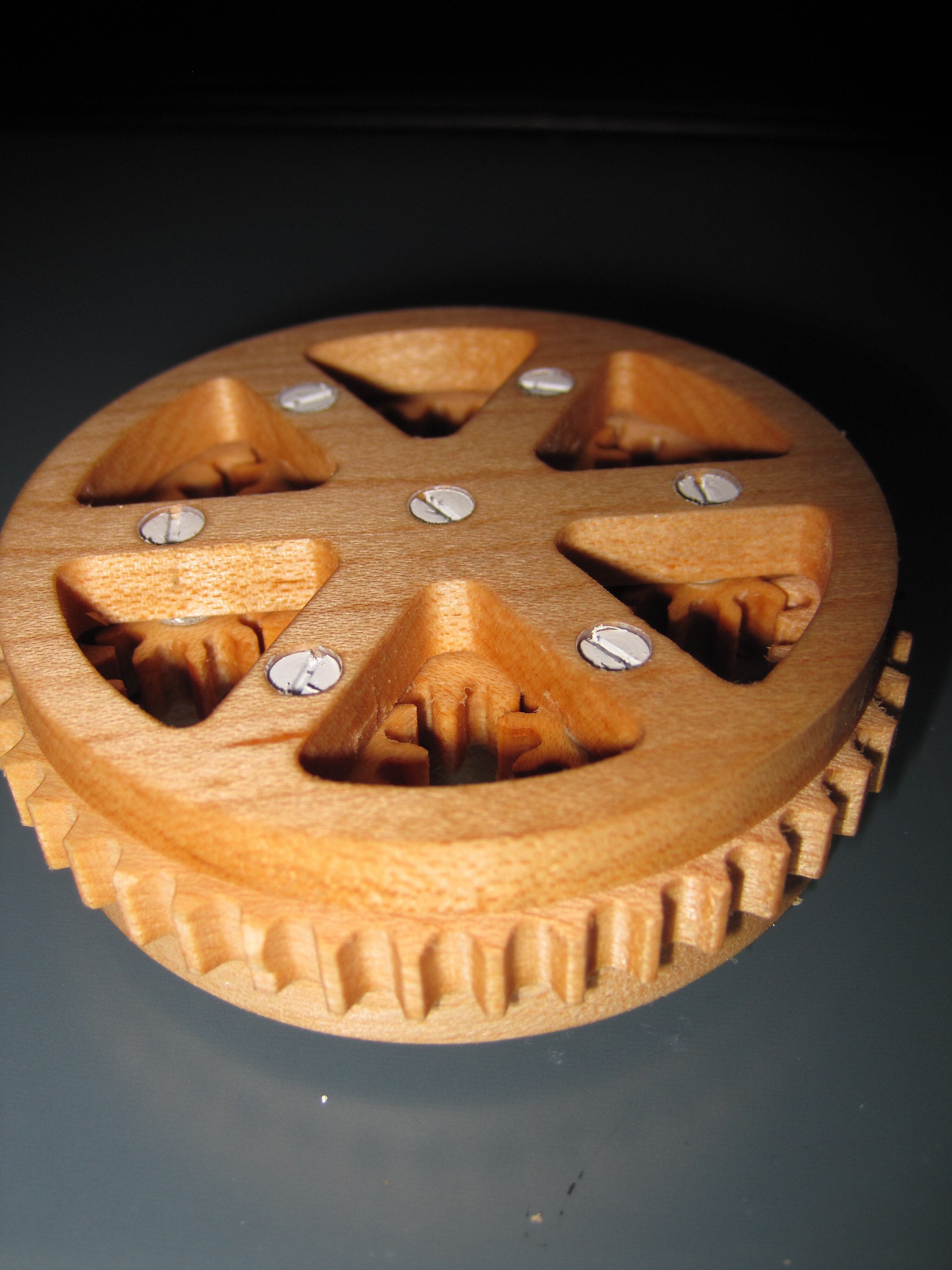
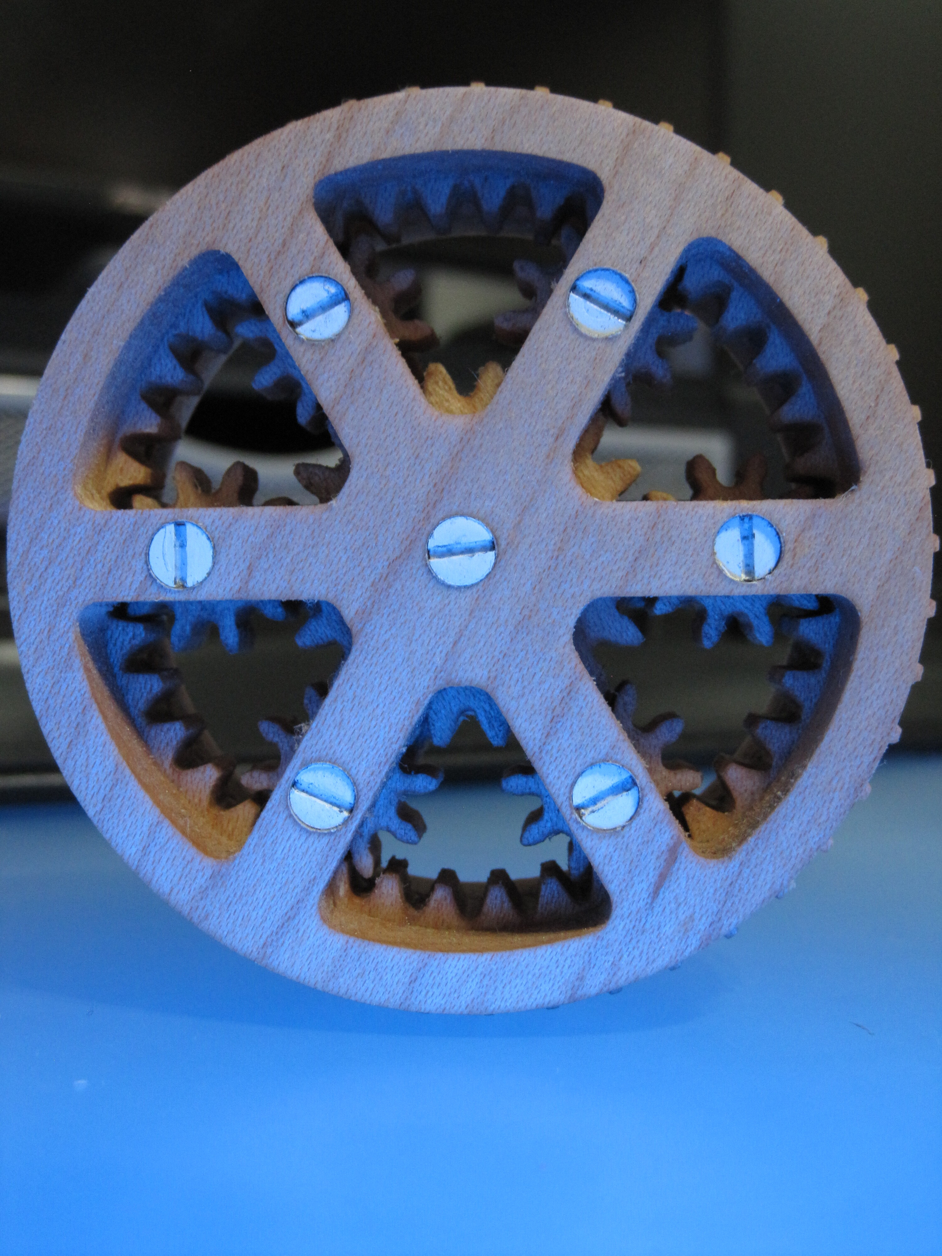
Planetary Gear
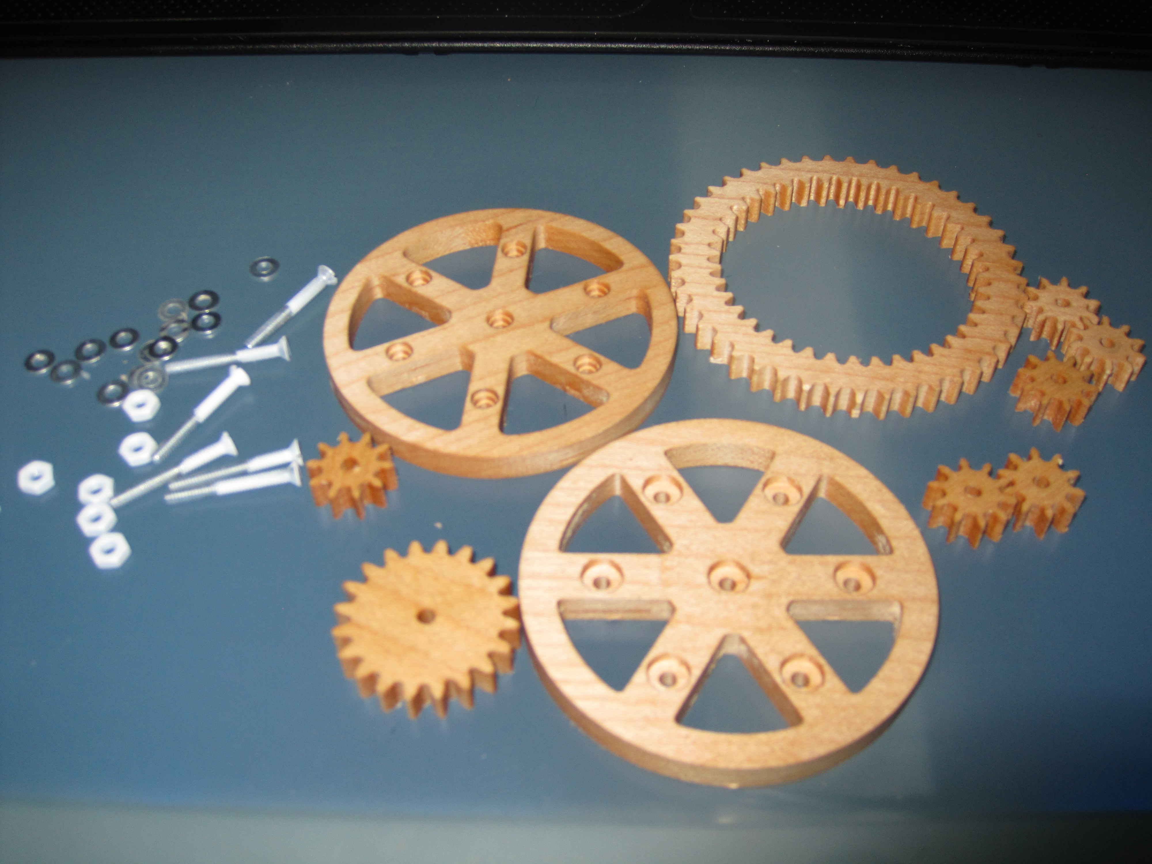
Made this on the Nomad, it’s quite small at 75mm x 75mm (roughly 3" x 3") so it’s a fun project to run on some scrap wood. I used some 1/4" thick maple, but the dimensions are not that important, you’ll end up with 3 layers once assembled.
I had to start by researching Planetary Gears, got lost in the math of trying to calculate gear dimensions, tooth pitch, tooth count, etc. Ended up finding an ~okay~ gear simulator here, mixed those results with some photos, and edited that in photoshop. Once I had the 8 gears (don’t want to use the word ‘designed’), more like ‘hacked’ together I then imported into Carbide Create.
The results where then tweaked, top and bottom holders were designed which resulted in this…
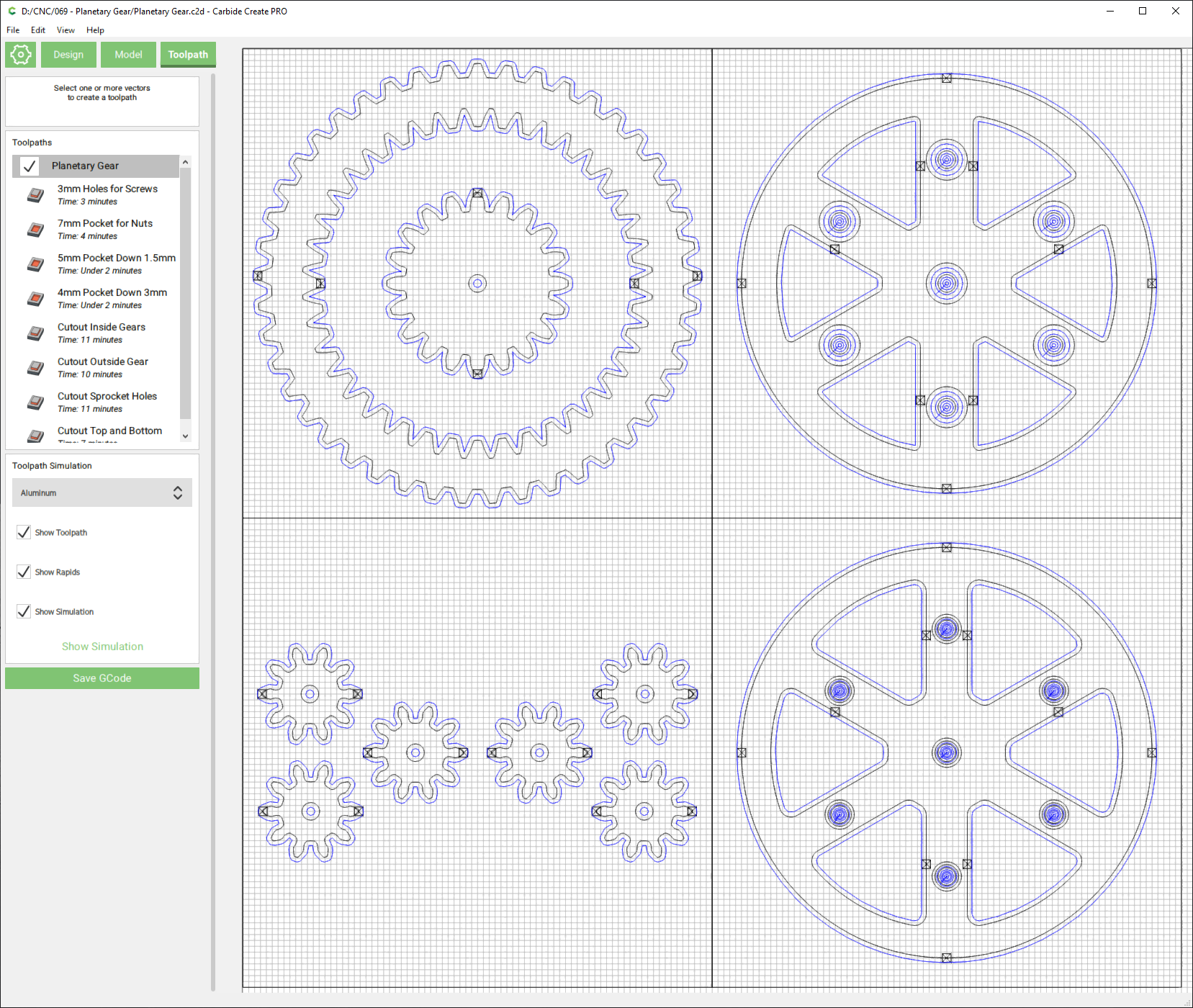
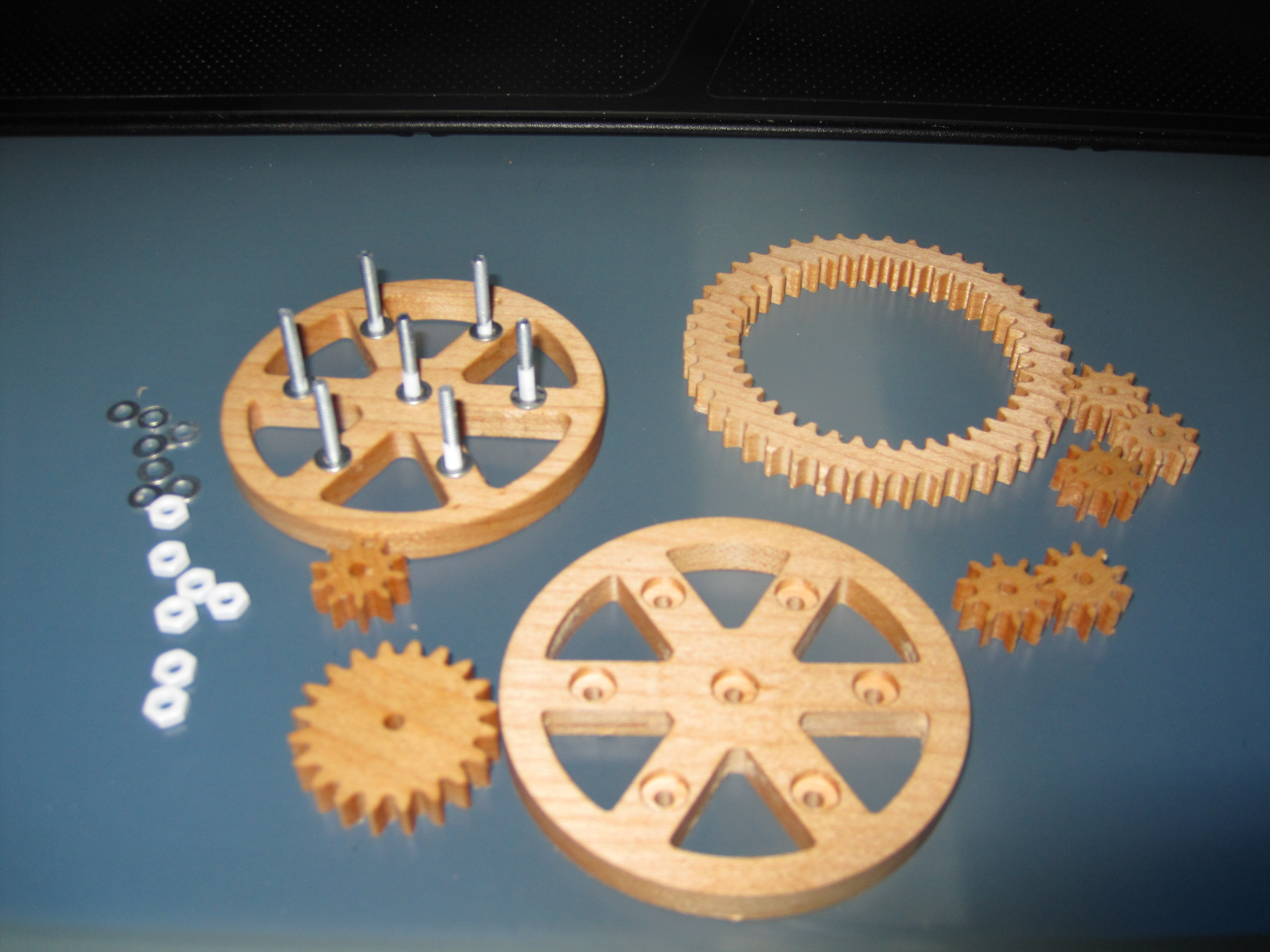
The design for the top and bottom (right side of the model) were constrained to what hardware I could find, pocket holes for the nuts and screw heads. I have mixed feelings regarding the use of tabs in this project. Assembly took longer because of the tabs, next time I will probably remove the tabs from the model and use lots of tape. However if you scale this design up to a larger size the tabs may be a better route.
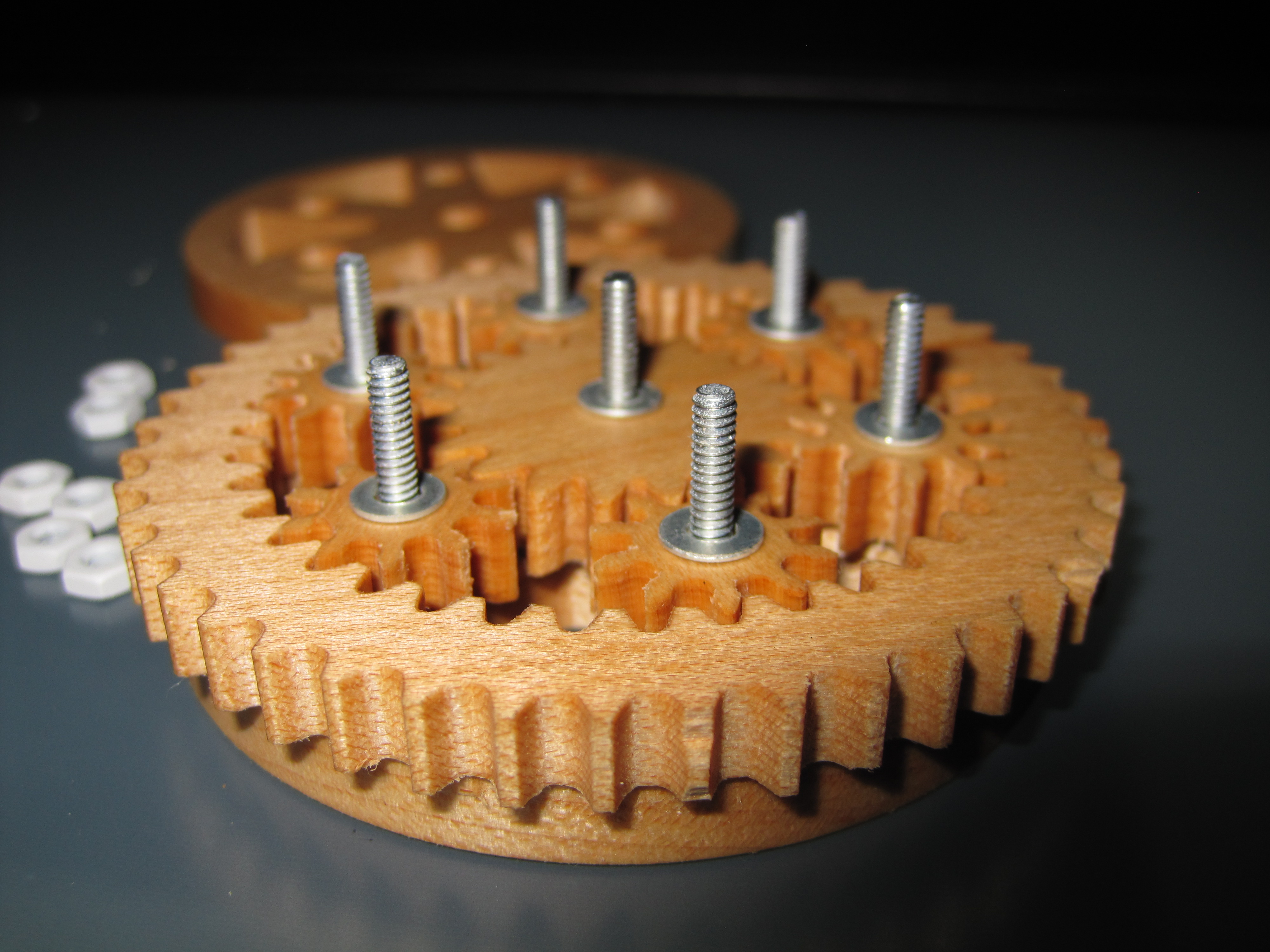
Assembly was easy, in photoshop I was able to eyeball how the gears would fit, and had reduced the size of the six planet gears which resulted in a nice loose fit once CNC’d.

Planetary Gear.c2d (2.9 MB)
This may end up as my goto project to use up scraps left over from other projects. This entire planetary gear could end up as one planet-gear within a larger planetary gear… hmmm.
14 Likes
Oh boy, you are really not helping me put my Nomad gear lust under control.
Thank you for your entry !
2 Likes
Here’s the Rummikub set again. Thanks @Julien for the notification.
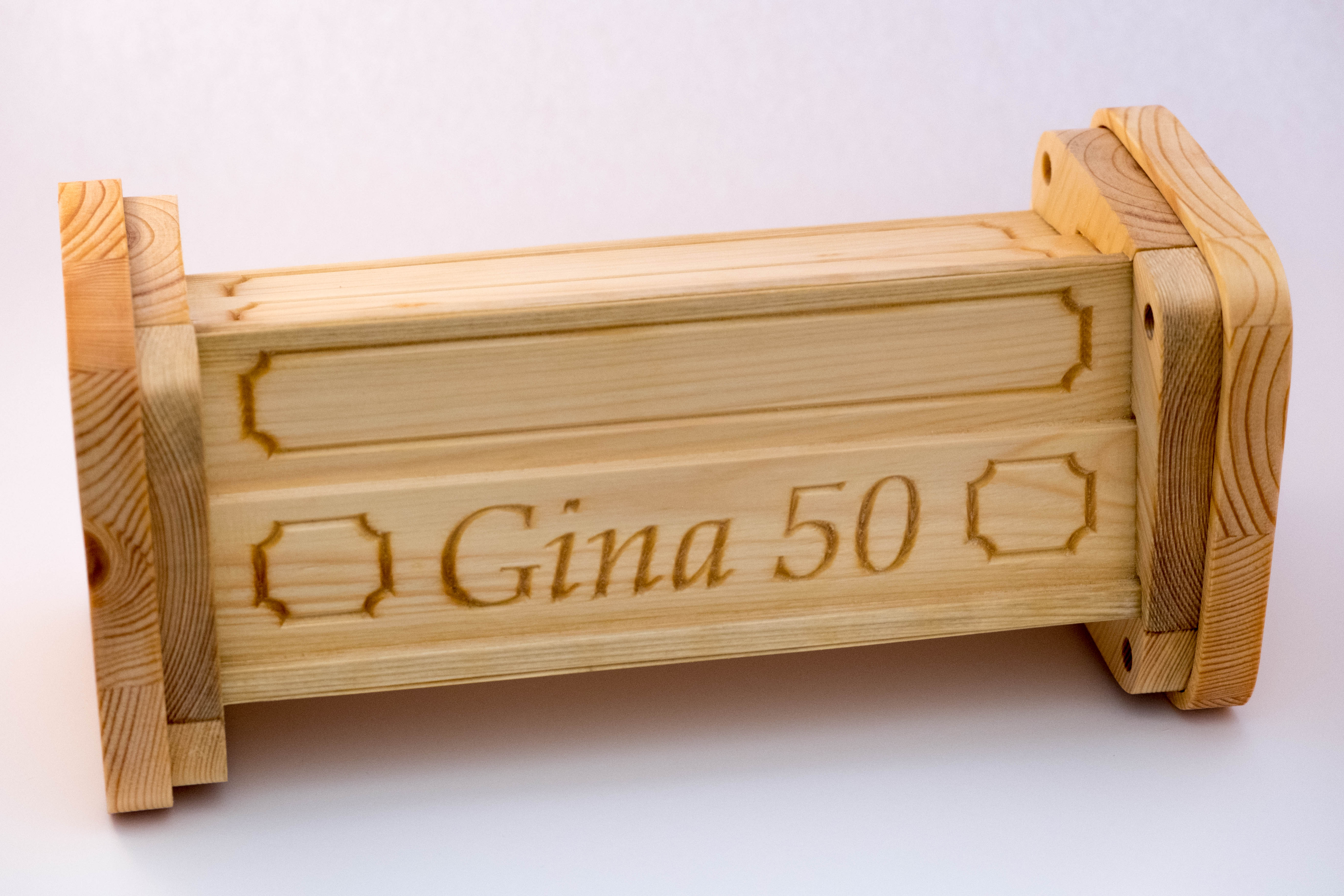
This set can be disassembled into four racks and these holding tablets (see left in the next image).

The racks fit onto the pins on the tablets to make the assembled box somewhat stable.
The number tiles are finished with color now …

… and while it wasn’t meant to look like that, I like how the color has found its way into the wood fibers occasionally:
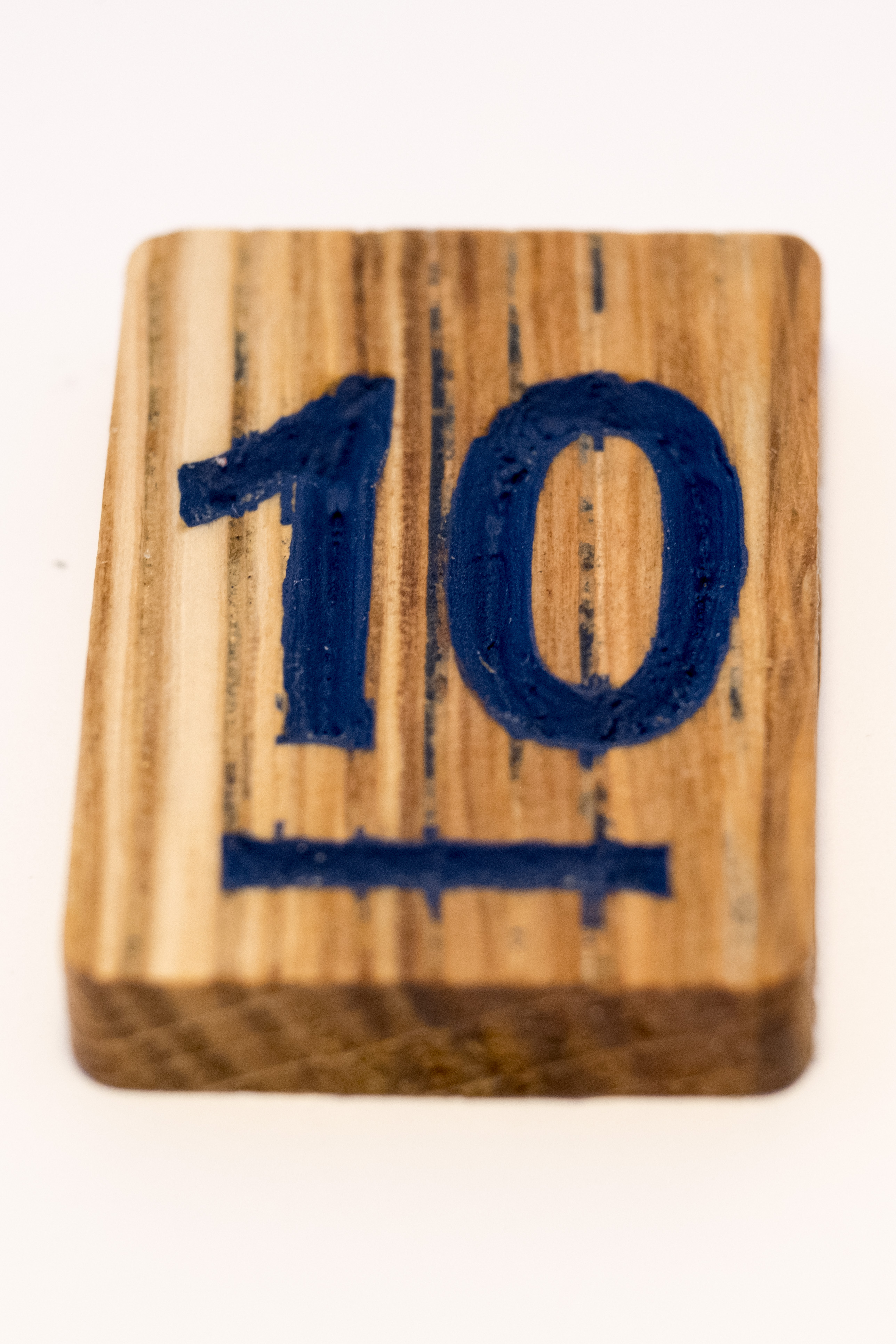
This actually brings me to the question, how you guys manage to get those super clean edges when coloring engravings?
I grounded the tiles with linseed oil, let it dry, applied the color (overlapping the edges), let it dry and then sanded off the top. However, as you can see, while sanding the top I also worked the color into the wood at some places.
Overall, I learned a lot of beginner’s lessons with this project. Most importantly probably that cutting pockets parallel to the wood fibres can cause very large fibres to tear out (at least for pine), so that I started to rotate the design or the stock in order to prevent this.
Here are the files:
rummi.zip (268.0 KB)
Regards
Nils
9 Likes
Thanks for the update @nlichtenberg. What you get in those color tiles is “bleeding”, i.e. paint/pigment finding its way into the wood fibers (some woods are more sensitive to this, depending on their grain). One trick to avoid this is to apply a coat of shellac/varnish/lacquer/anything transparent really, to seal the areas you just cut. Let dry, and then apply your paint, and sand like you did.
Yup, I’ve been there. Either cutting at an angle or using a downcut endmill takes care of that problem.
4 Likes
Very cool Nils, glad you reposted!
2 Likes
2.5 days to go before the deadline, don’t be shy and let’s see those last minute entries!
(last time, @duexx took the “last minute” concept very literally by submitting 3 minutes before midnight!)
I can’t believe @Vince.Fab asked that question but had nothing in mind 
3 Likes
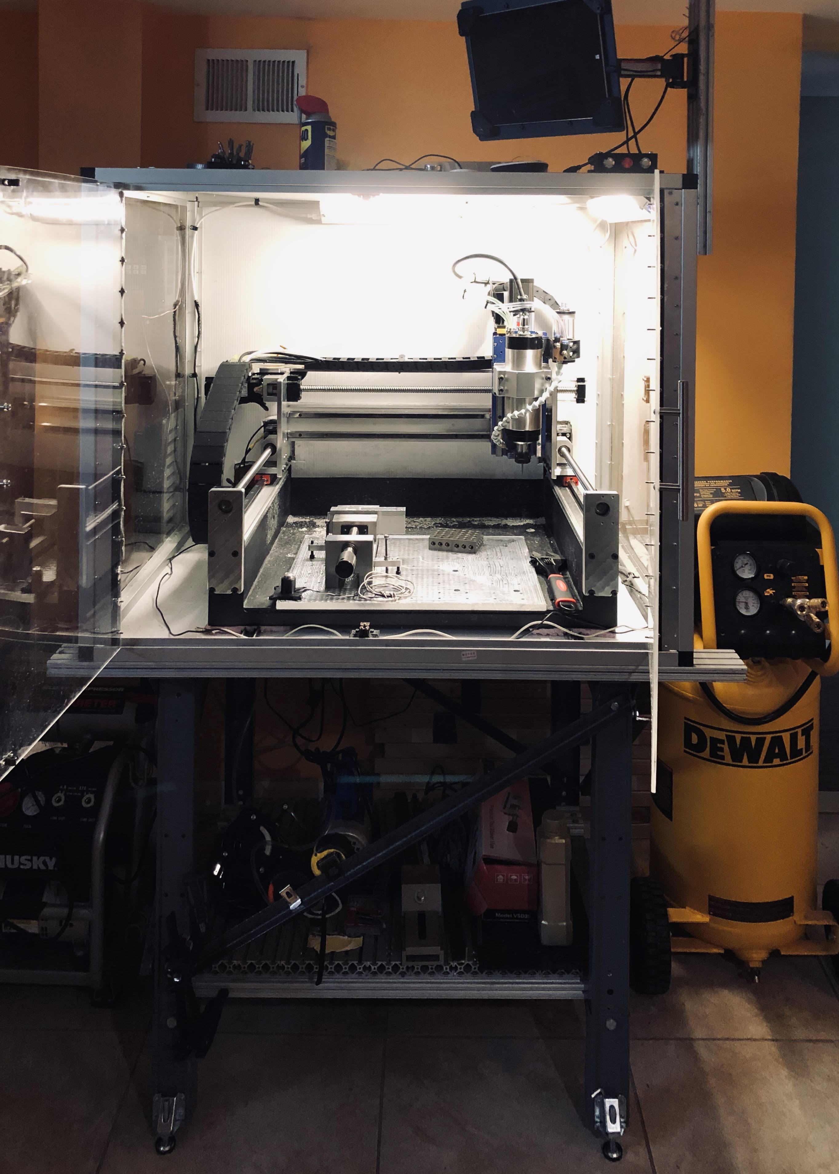
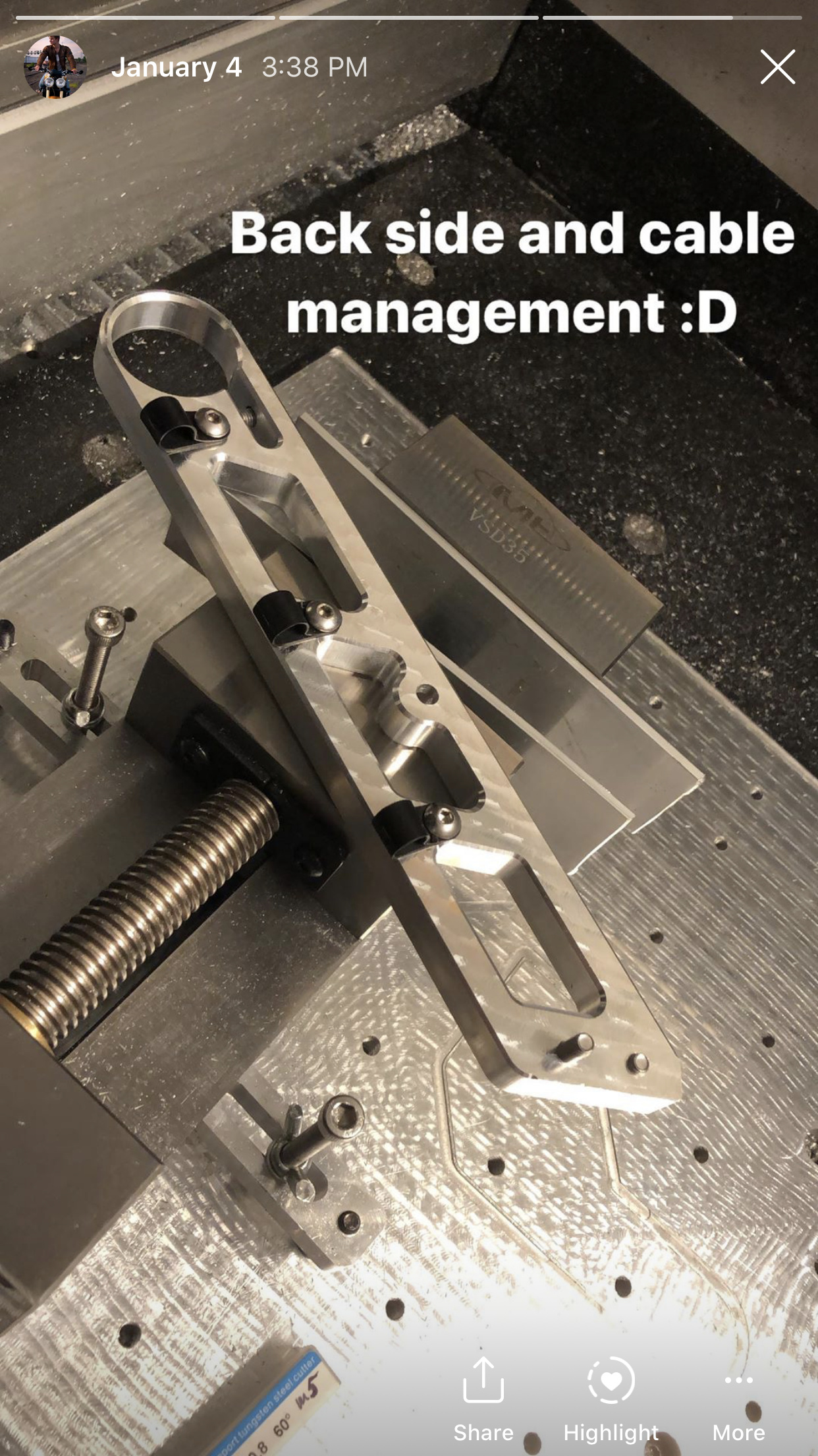
Hi guys, the project I’m posting today is the sole reason for buying my Shapeoko’s and modifying them extensively. I documented upgrading smaller so3 to linear rails and ballscrews last summer but never actually followed up on how it performs, so this is how the machine looks today and it’s been a real pleasure to work on.
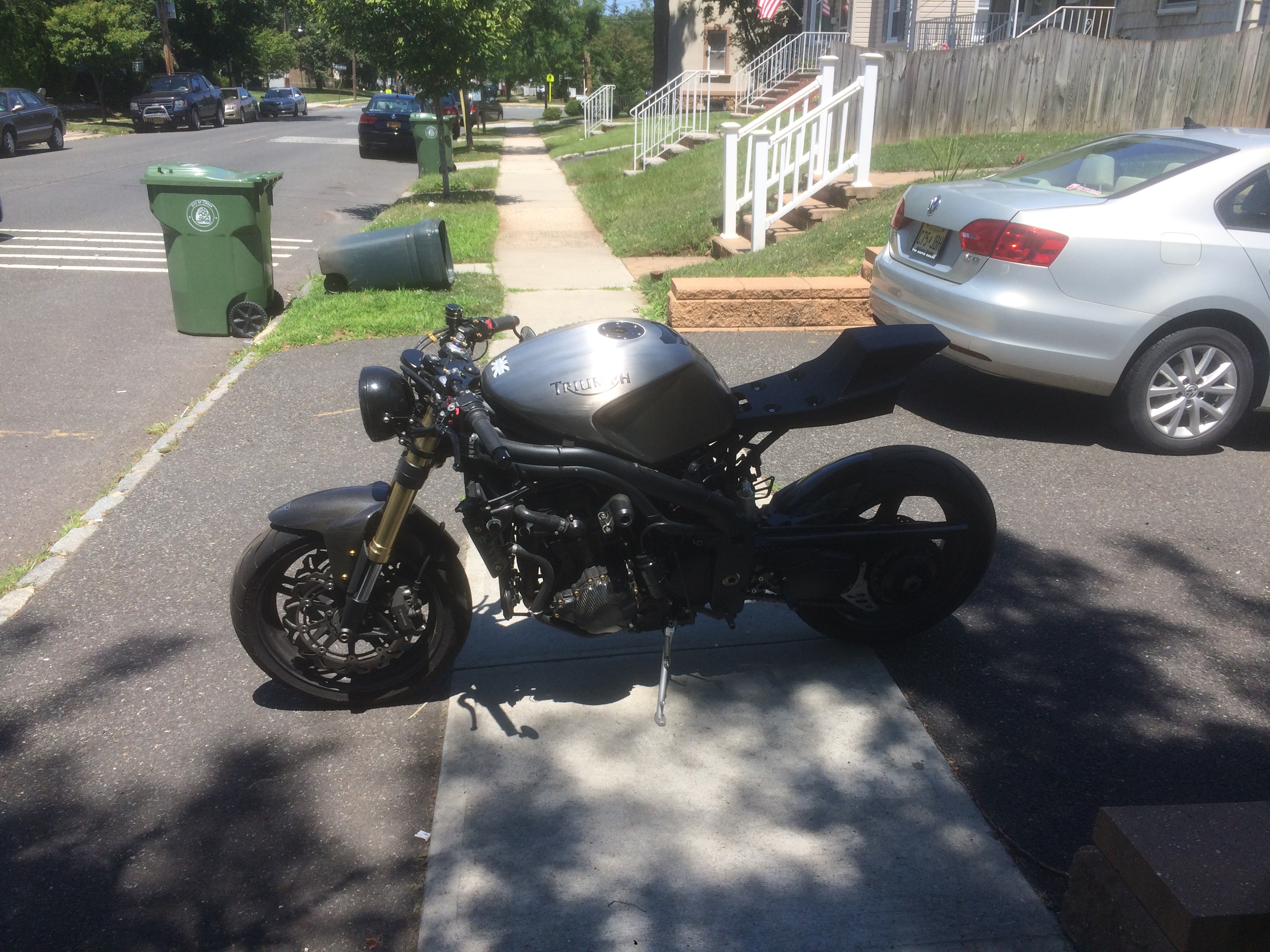
This project is actually a product that I’ve been developing for the past couple months. Coronavirus slowed down the progress as I’m having difficulty finding a company that would manufacture carbon fiber parts for me, but the majority of machined parts are ready. What I’m working on is a motorcycle cafe racer/street tracker kit for a 05-08 Triumph Speed Triple. The objective was to design a simple but visually appealing kit that would allow for quick change of style, by simply swapping mounting plates with seat units.
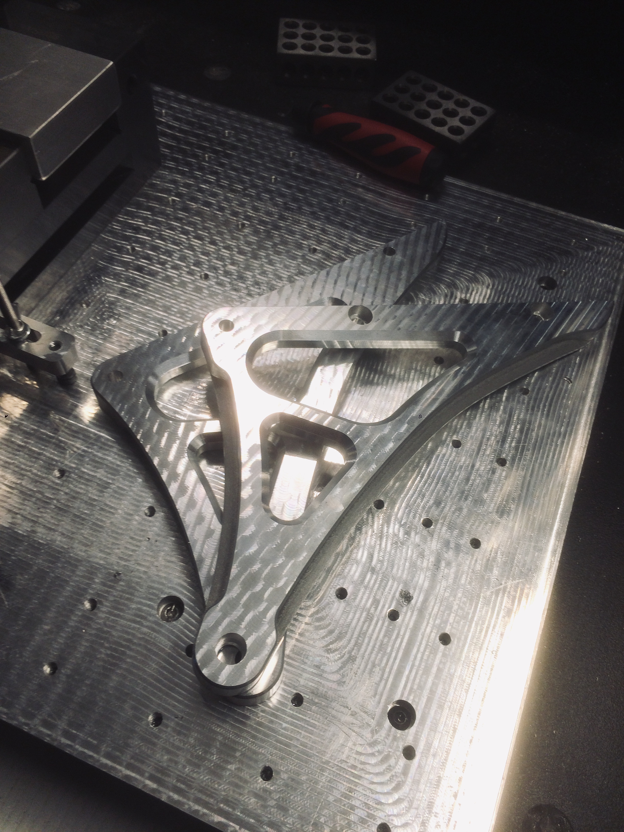
The design was heavily inspired by ‘Confederate motorcycles’ giving it industrial look, but also making it fairly easy to machine on the desktop cnc.
Don’t know if it’ll count as two entries or just one, but I’ll post both products that are part of the same kit.
#1 Minimalistic subframe with interchangeable seat units.

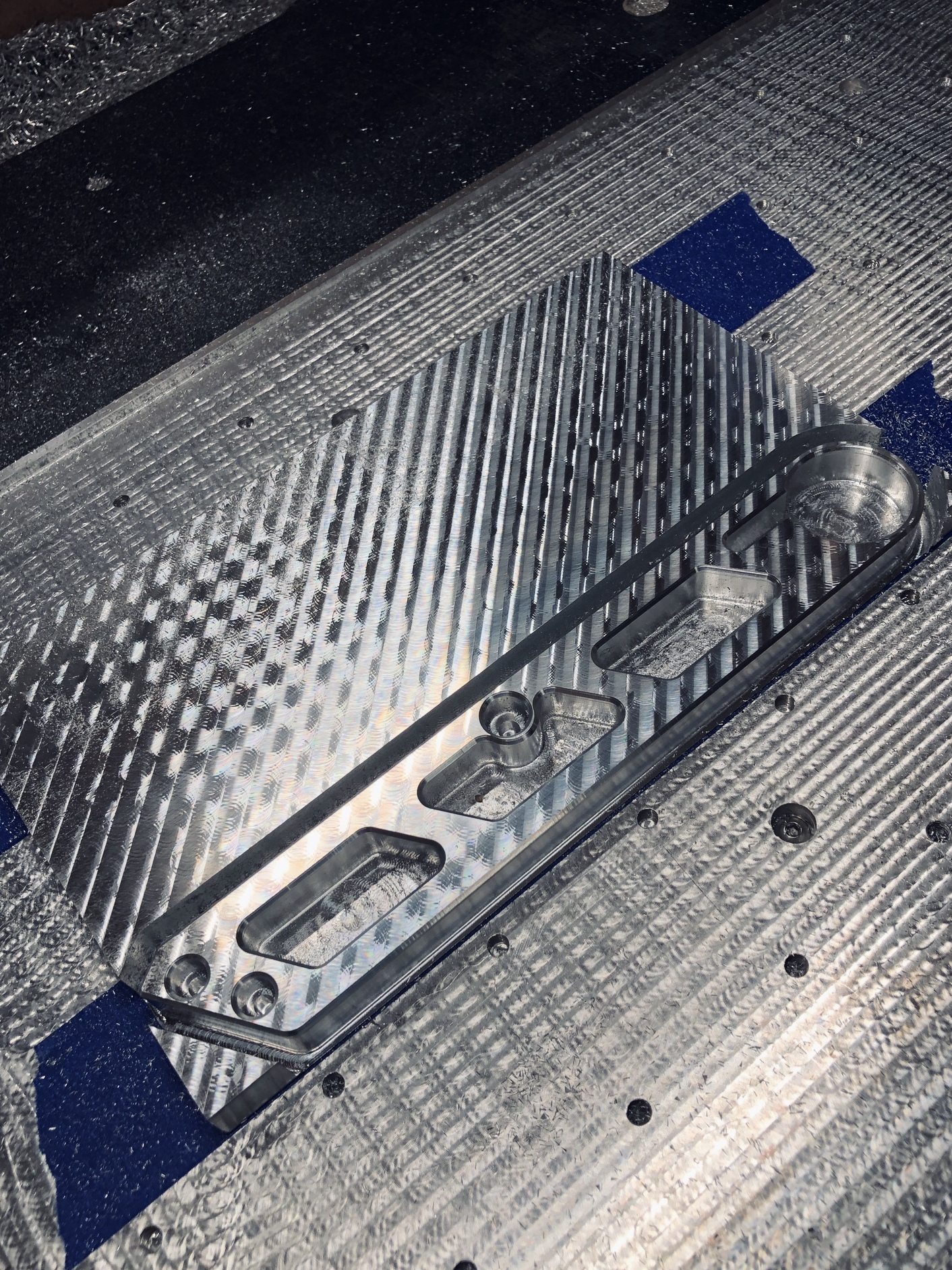
All the parts could technically be redesigned to be cut on the laser, plasma, or water jet, but machining them makes them look much nicer.


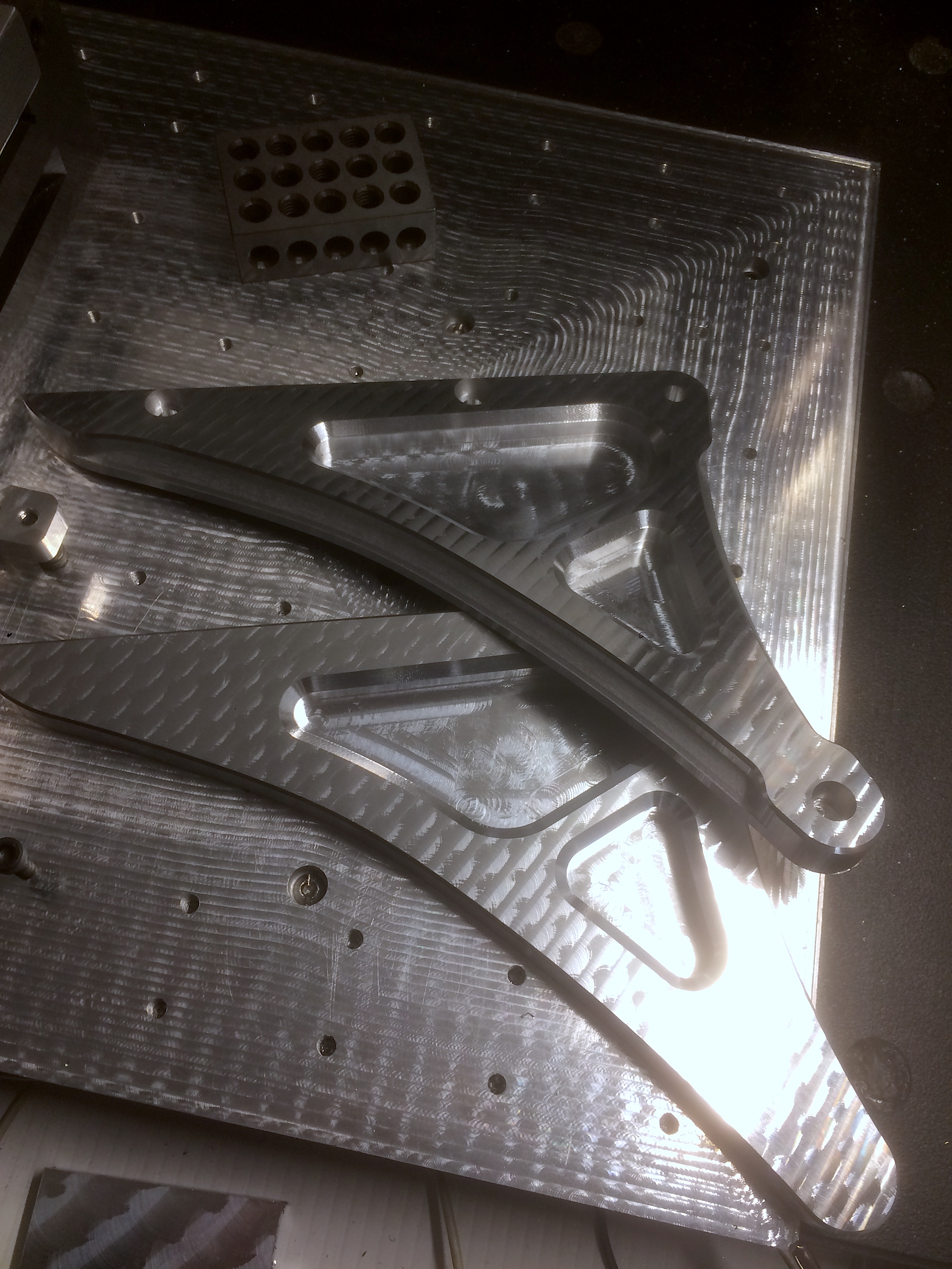
At the end of the post I’ll show how they all look mounted on the actual motorcycle.
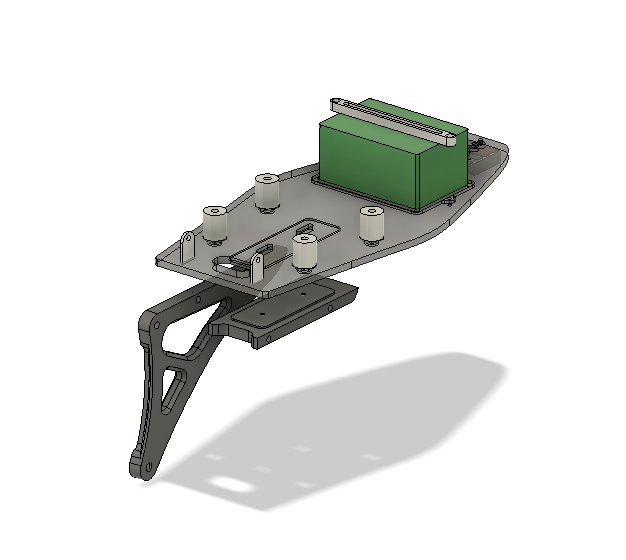
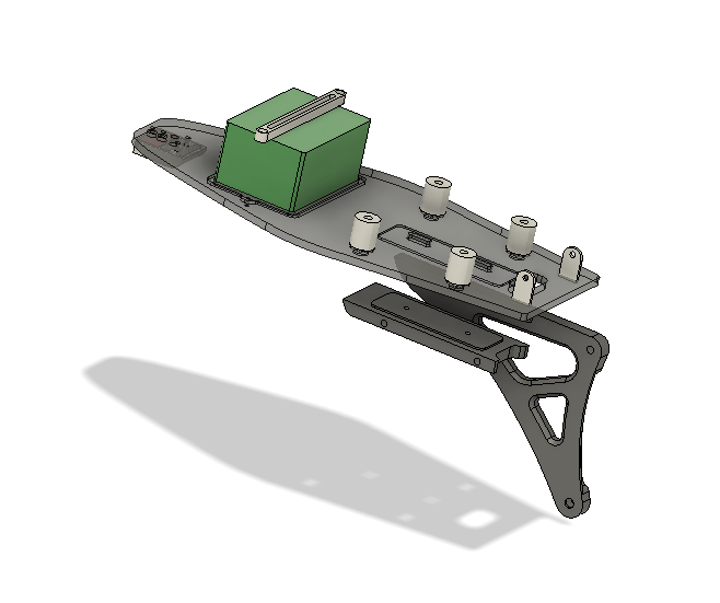
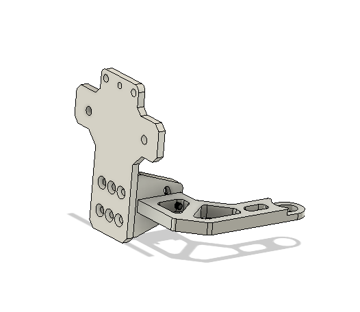
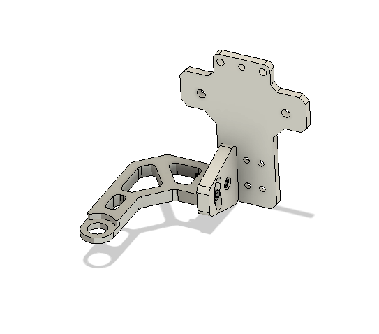
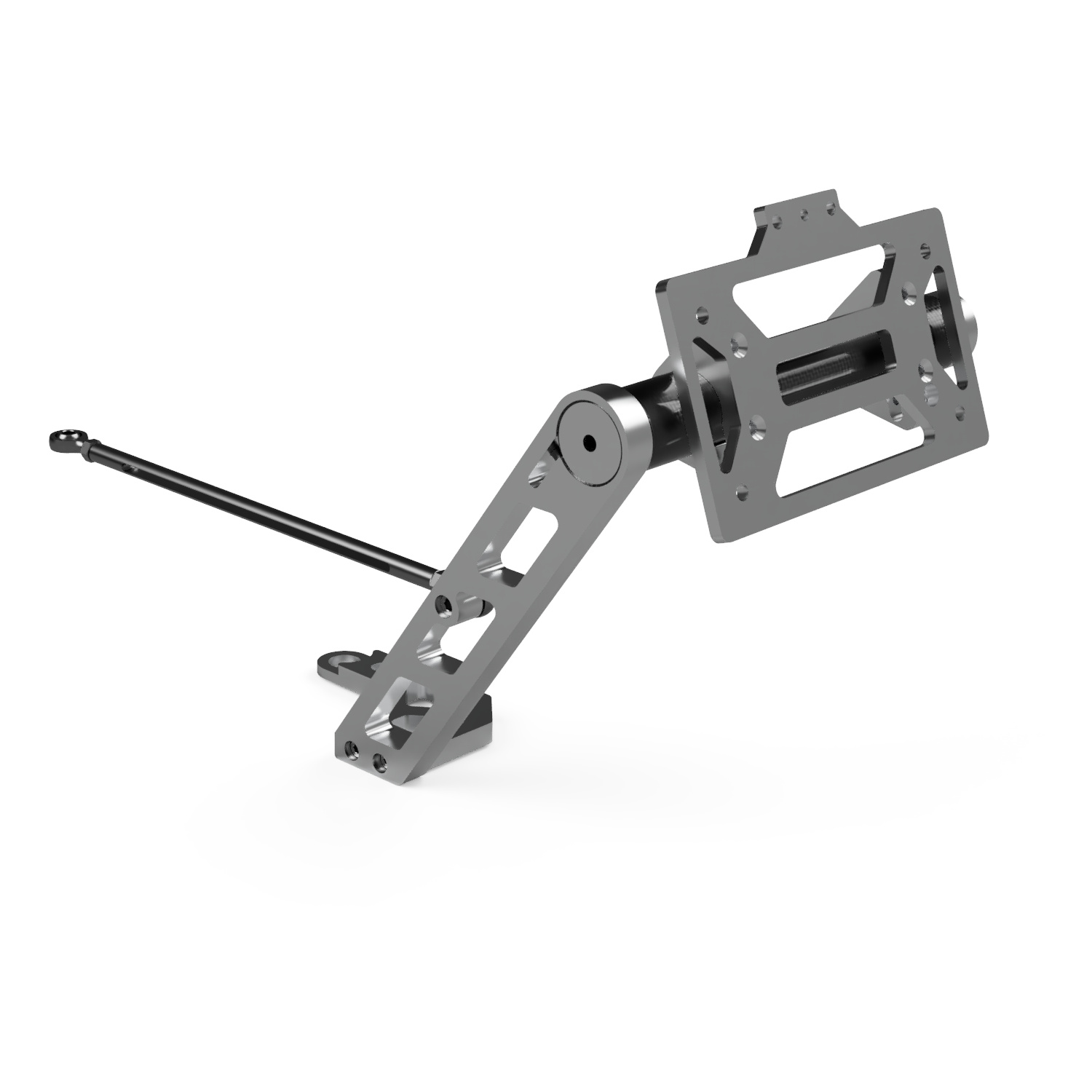
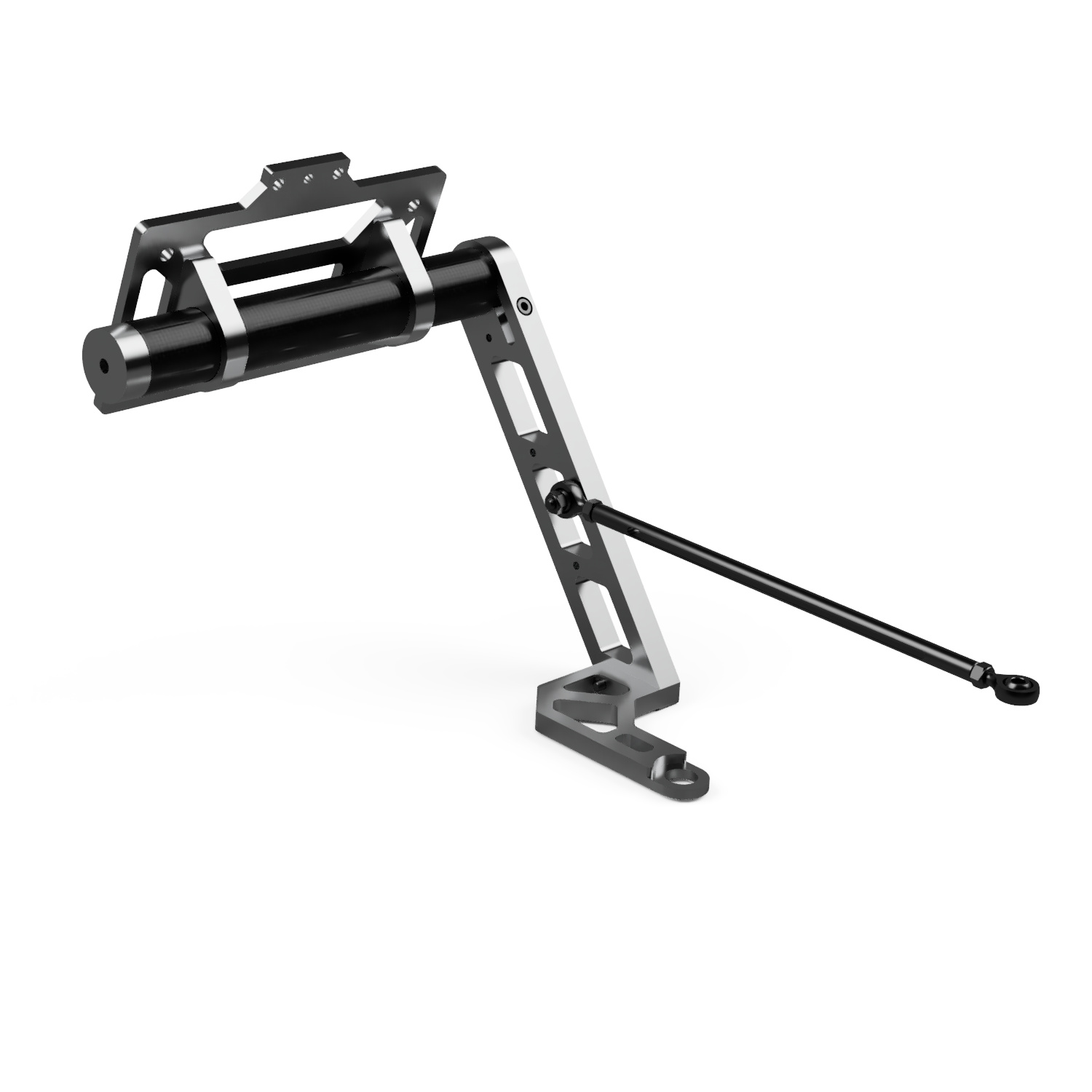
#2 License plate mount.
This will also use a modular design, allowing for either - mounting a license plate behind the sprocket, next to the rear wheel or extend all the way past the rear wheel. The second option also comes with the integrated turn signals.
Option 1
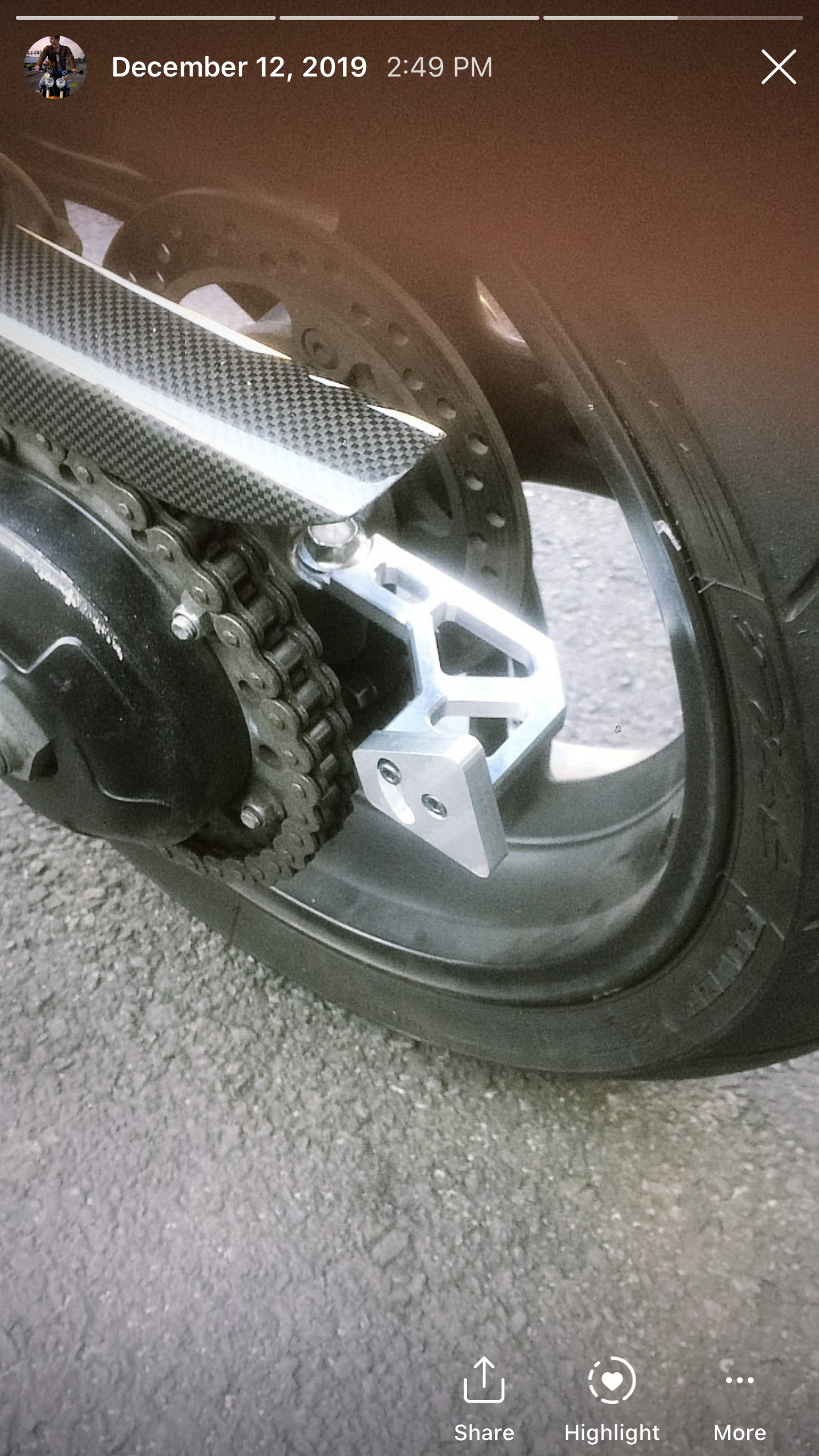
At the time of posting don’t have access to my workshop, so couldn’t take a picture with the actual license plate mounted in this location.
Option 2

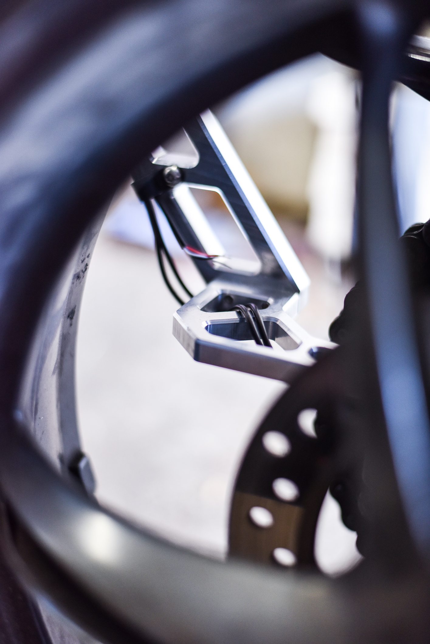
Finally, this is how all the parts look like installed on the motorcycle.
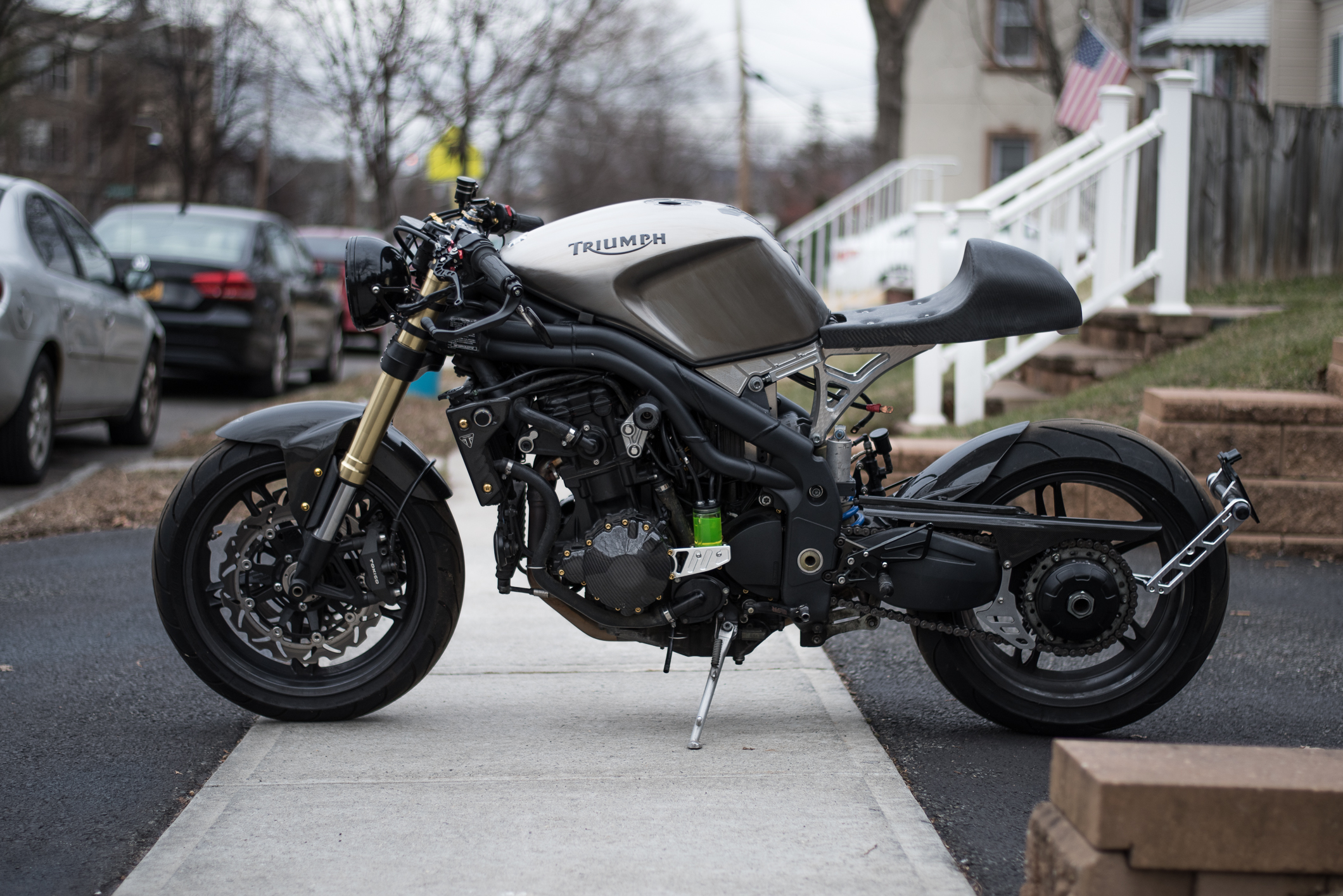
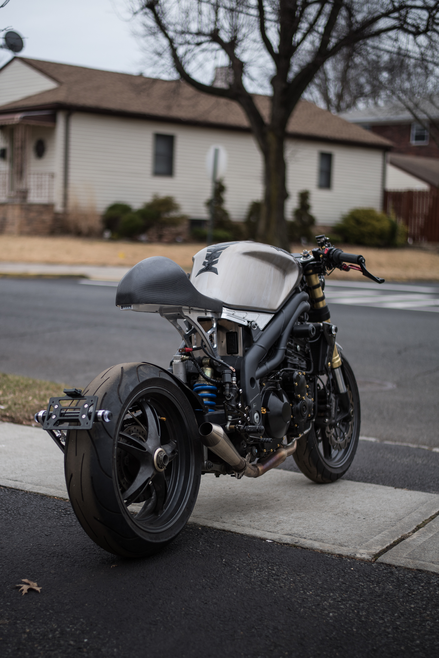
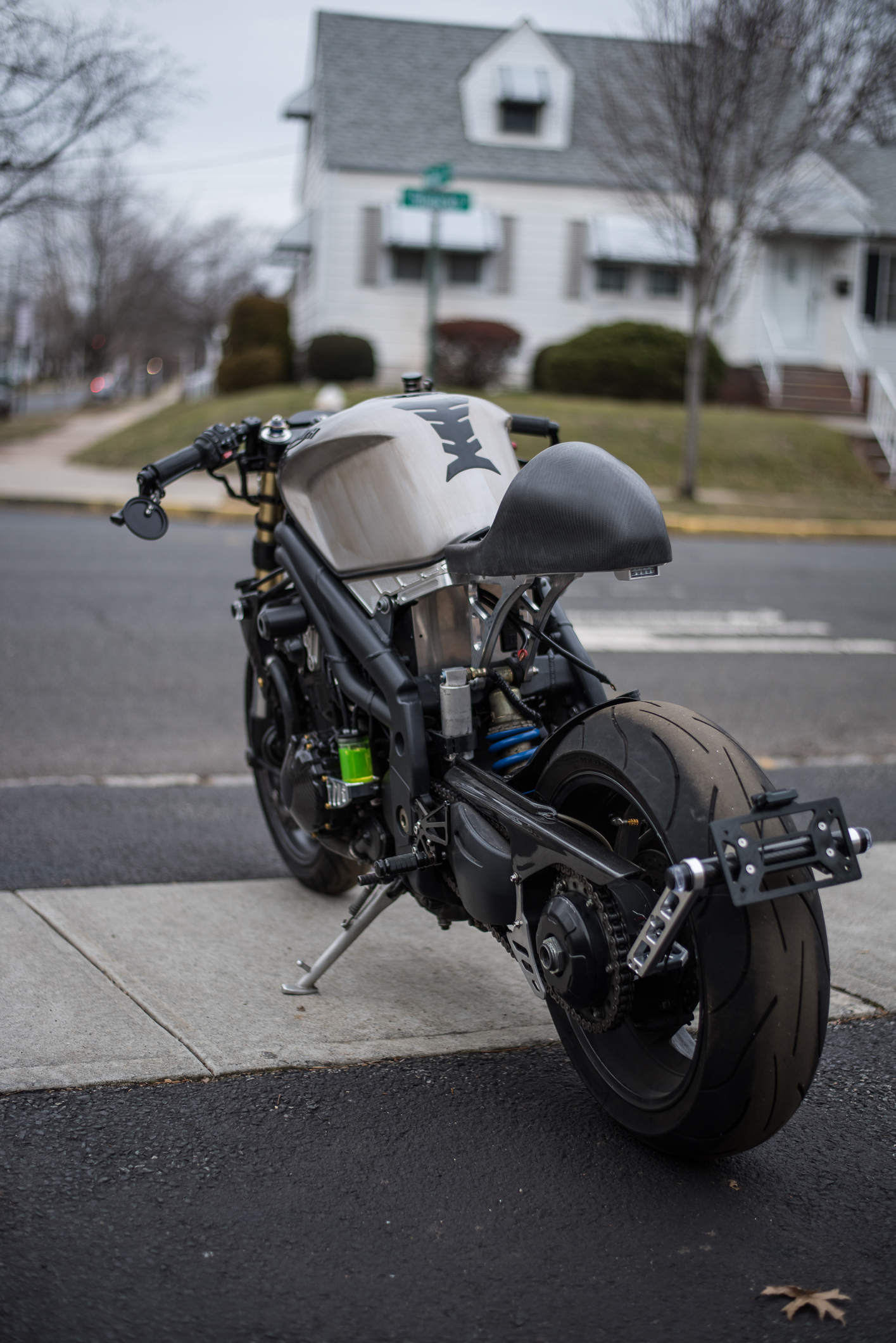
And also the unfinished street tracker seat.
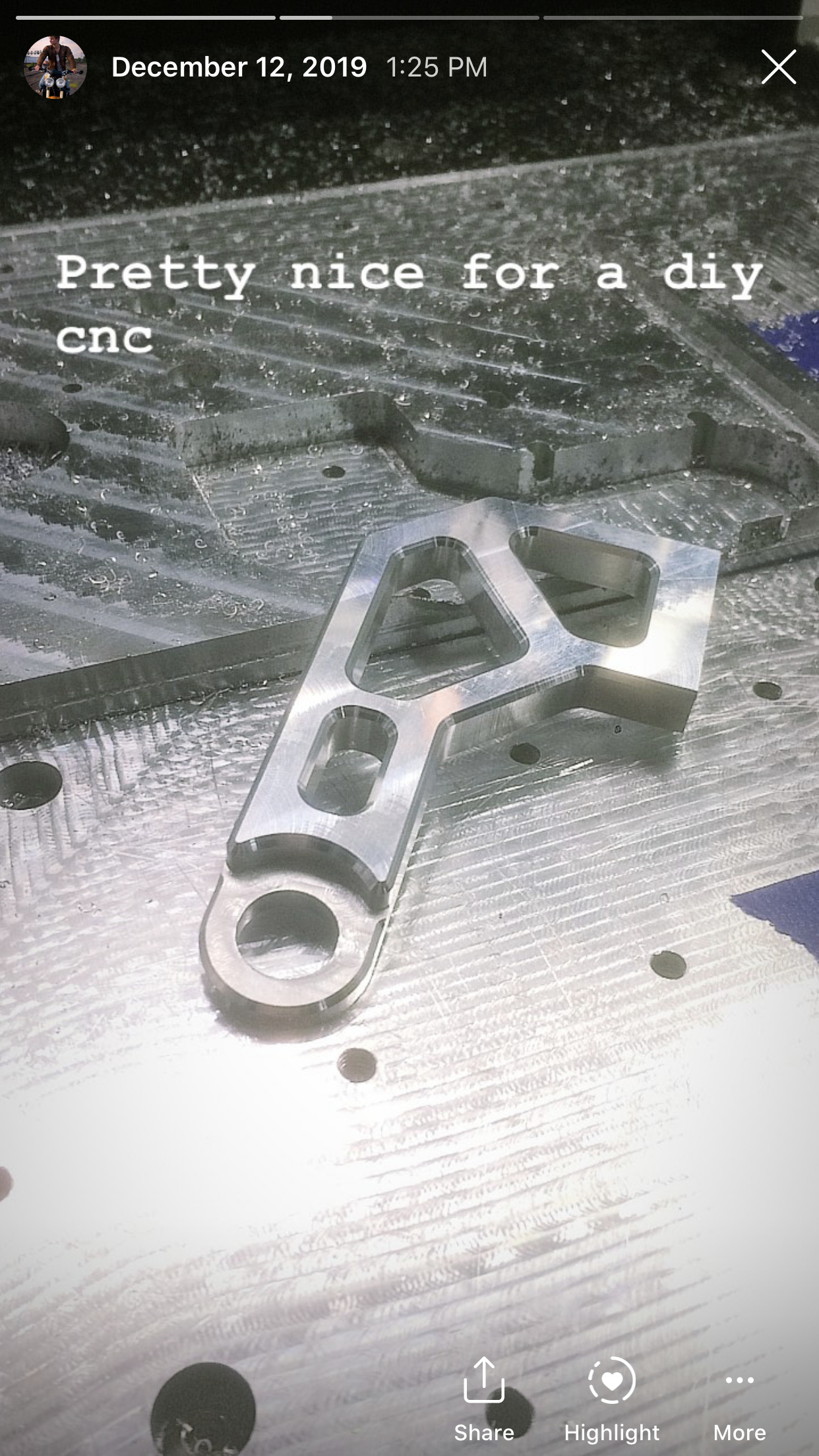
Sorry for some of the pics being pulled from the IG stories and other taken with some crappy cameras, but haven’t had a chance to properly photograph entire kit yet. Hope you guys like it. And if anyone would like to follow my cnc struggles my IG is: bk1photo
There’ll be much more cnc content soon.
10 Likes
Hi @BartK
Very impressive…I can only imagine the countless hours that went into this, it’s just beautiful and a testimony to why the Shapeoko rocks! (and you do too)
So it kills me to have to mention this, but I suppose you cannot/do not want to share the associated design files, which was one of the rules of the challenge 
Is there part of it that you could share so that people could benefit from e.g. your toolpath strategy, feeds and speeds, etc? in the spirit of validating the entry.
1 Like
Thanks @Julien
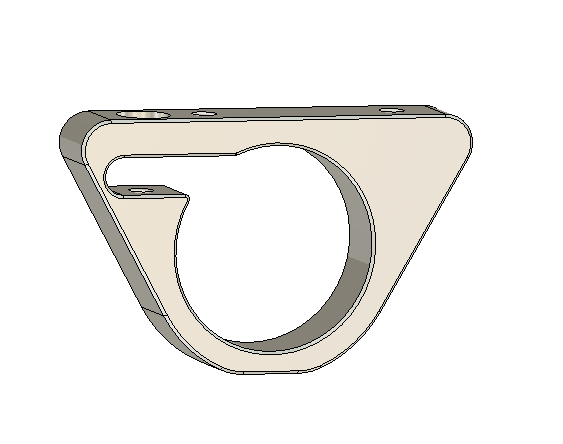
I honestly missed the part where we have to upload the project and the tool paths, although that makes sense. The only part of the project that I can create separate file for and upload so others can see my technique would be those clamps.
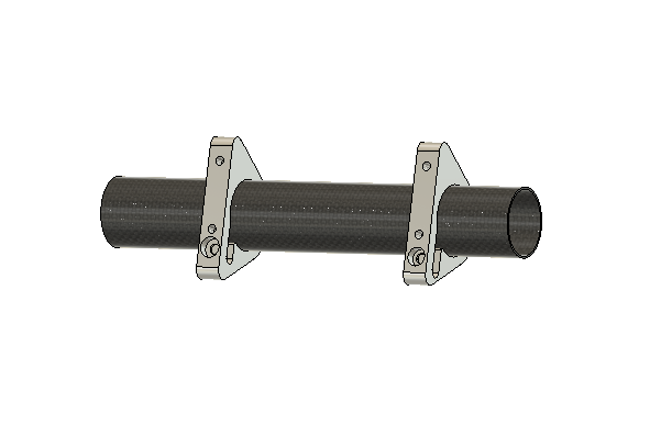
They’re slightly oversized to fit onto a carbon fibre tube and allow for adjusting the angle at which license plate sits behind the wheel. I can make a separate Fusion360 file for it. If that’s not enough then ‘ohhhh well, happens’ lol
3 Likes
I’ve been known to bend the rules before (and I’ve been called a pushover for doing it, ha!), so as far as I am concerned, if you do make the effort to share a sample file and tell us about your approach/tips to cut shiny parts, it will be valid. Since the entries will be submitted to vote anyway, people who think otherwise will be free to not vote for you
2 Likes
Cool, I’ll make a post about my workflow and will post the file as well.
Hi, everybody,
I made a decoration for my house. (a frame)
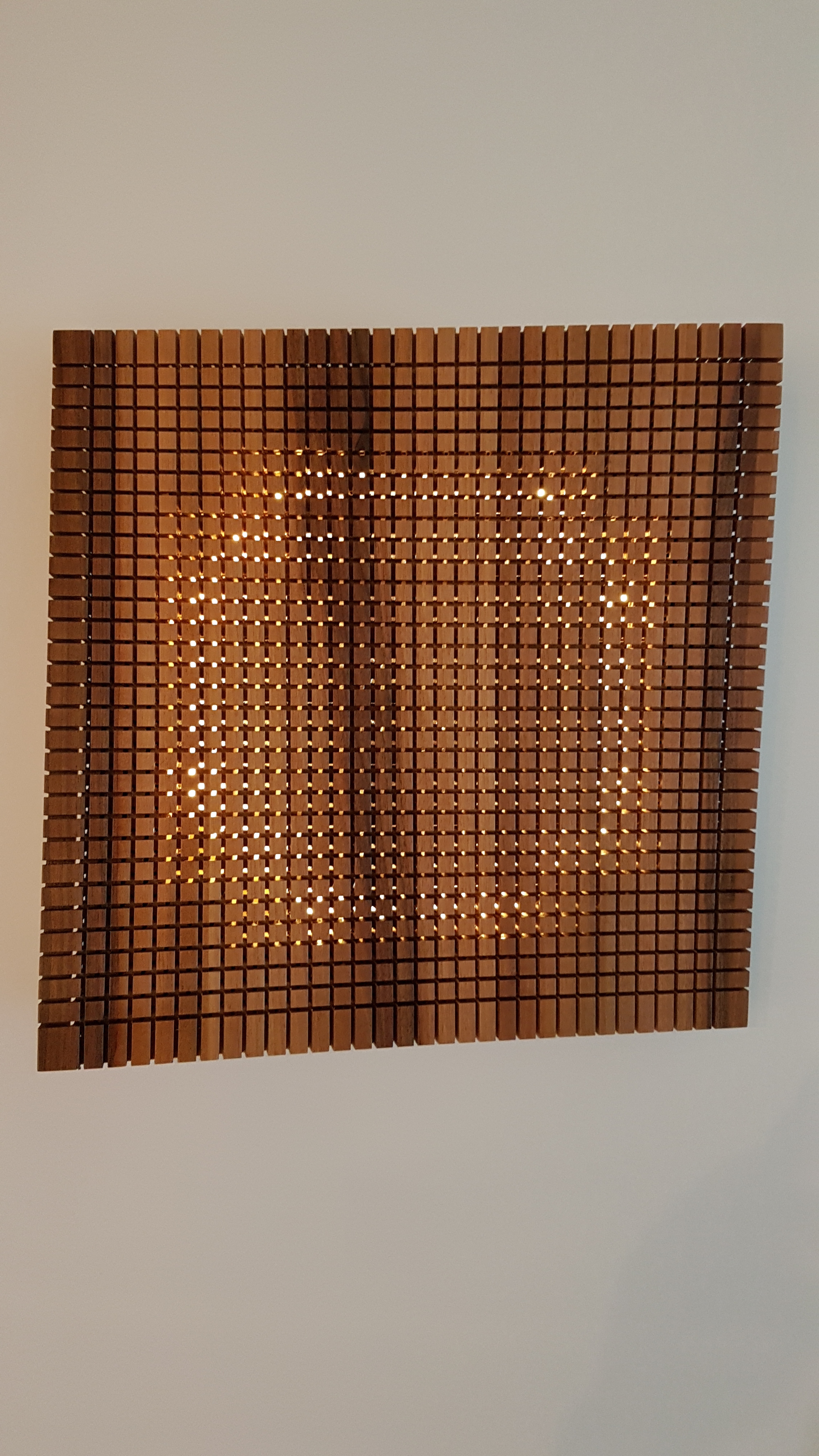
I put it in two times… I looked for a shape that I really liked, in the shape of waves, but a little too pronounced for what I wanted to do.
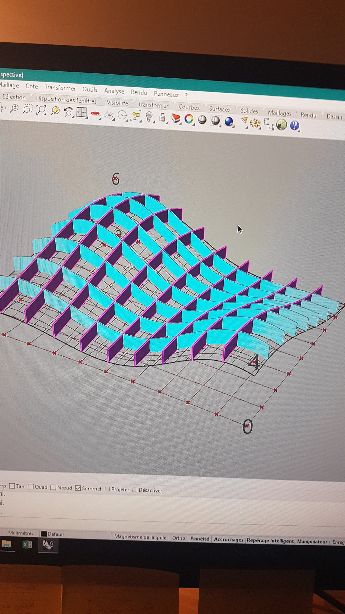

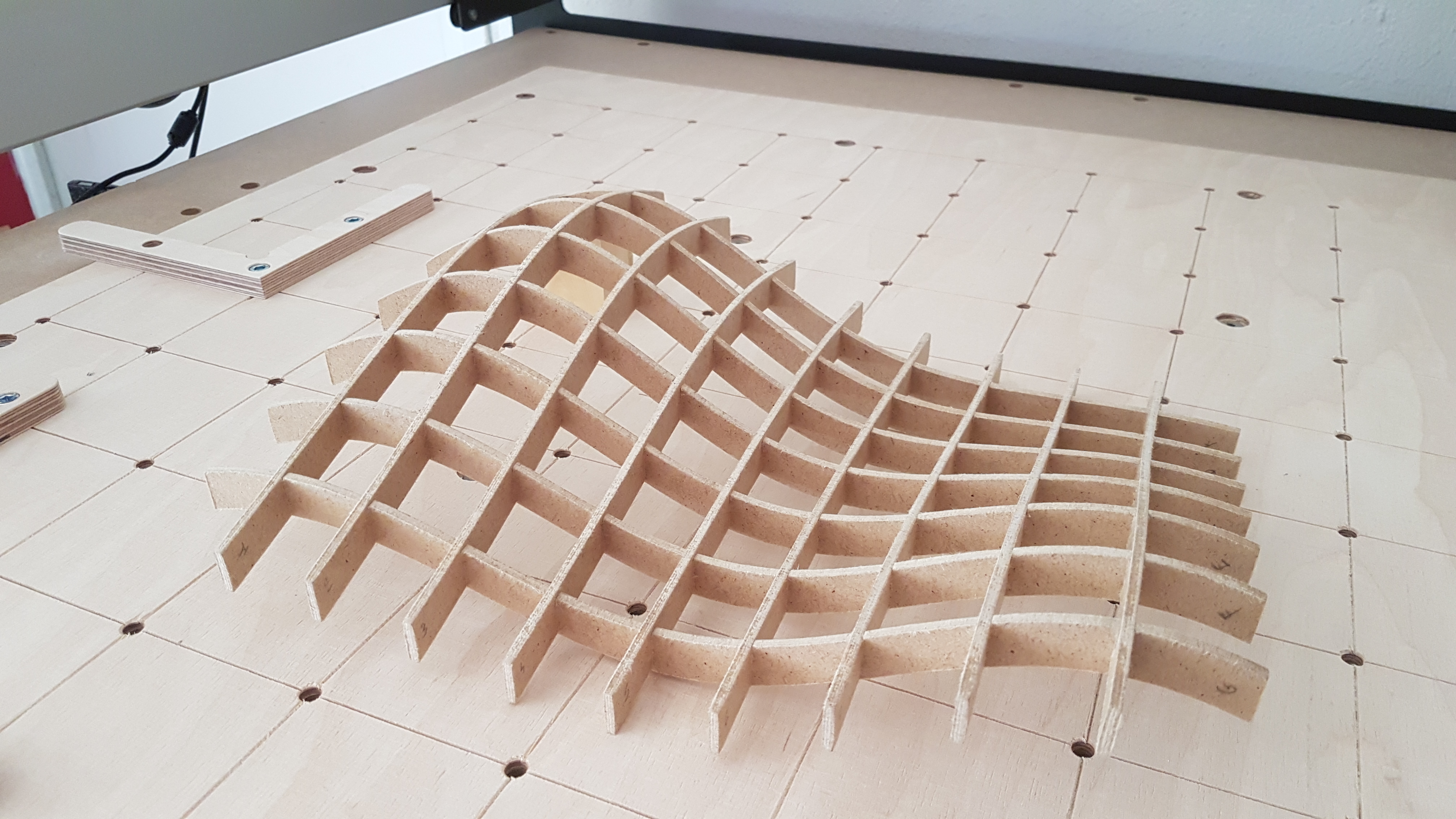
So I made a frame with a simpler shape, but that I could fix “a soft wood” on it. that the cladding be constrained in both directions of the wood. In French we say gauche…
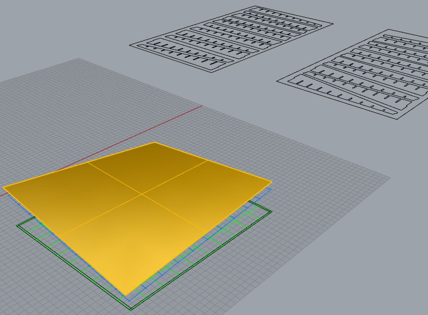
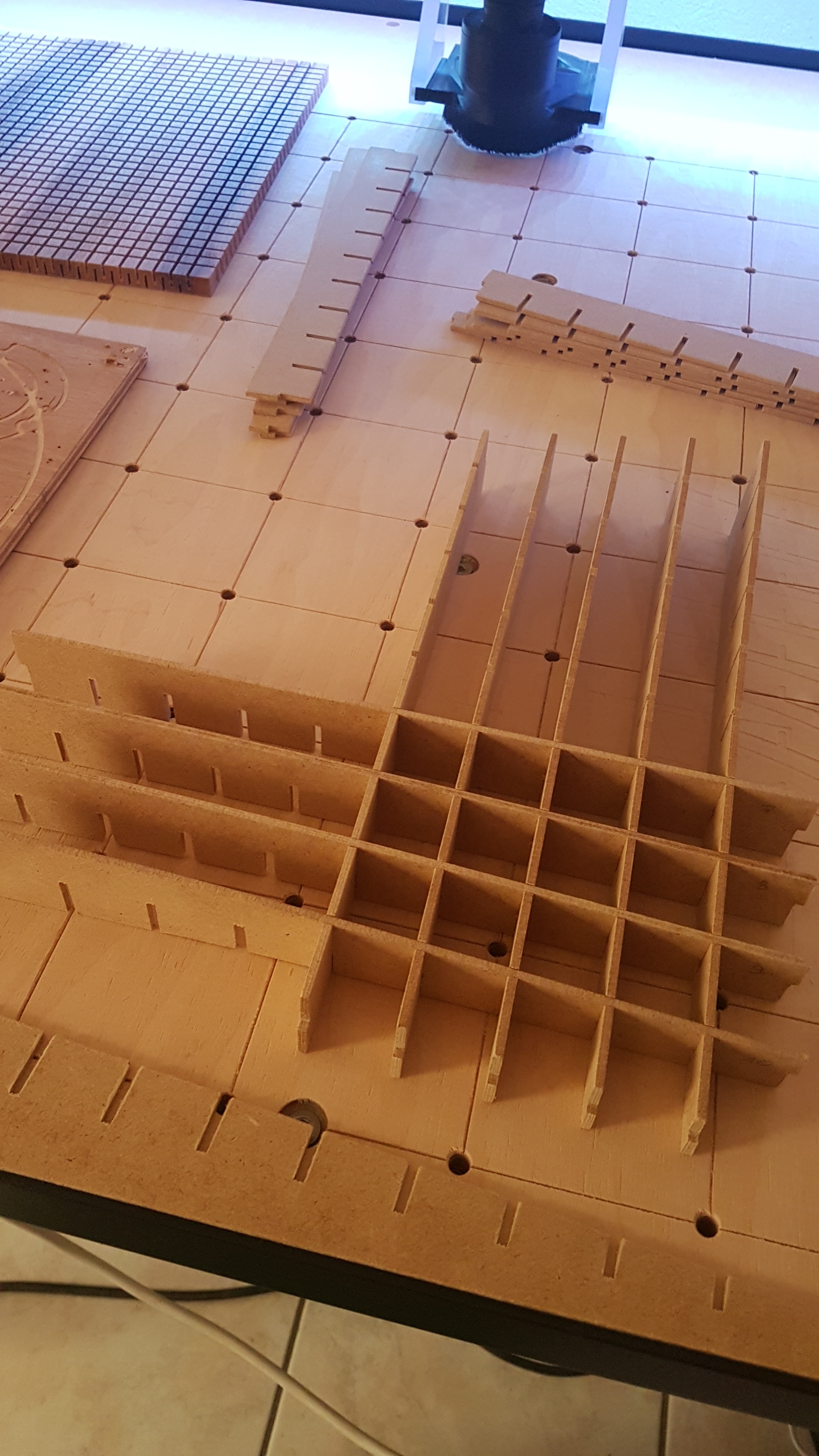


Then I had the idea to introduce a led ribbon inside. to make it more fun, and more trendy 
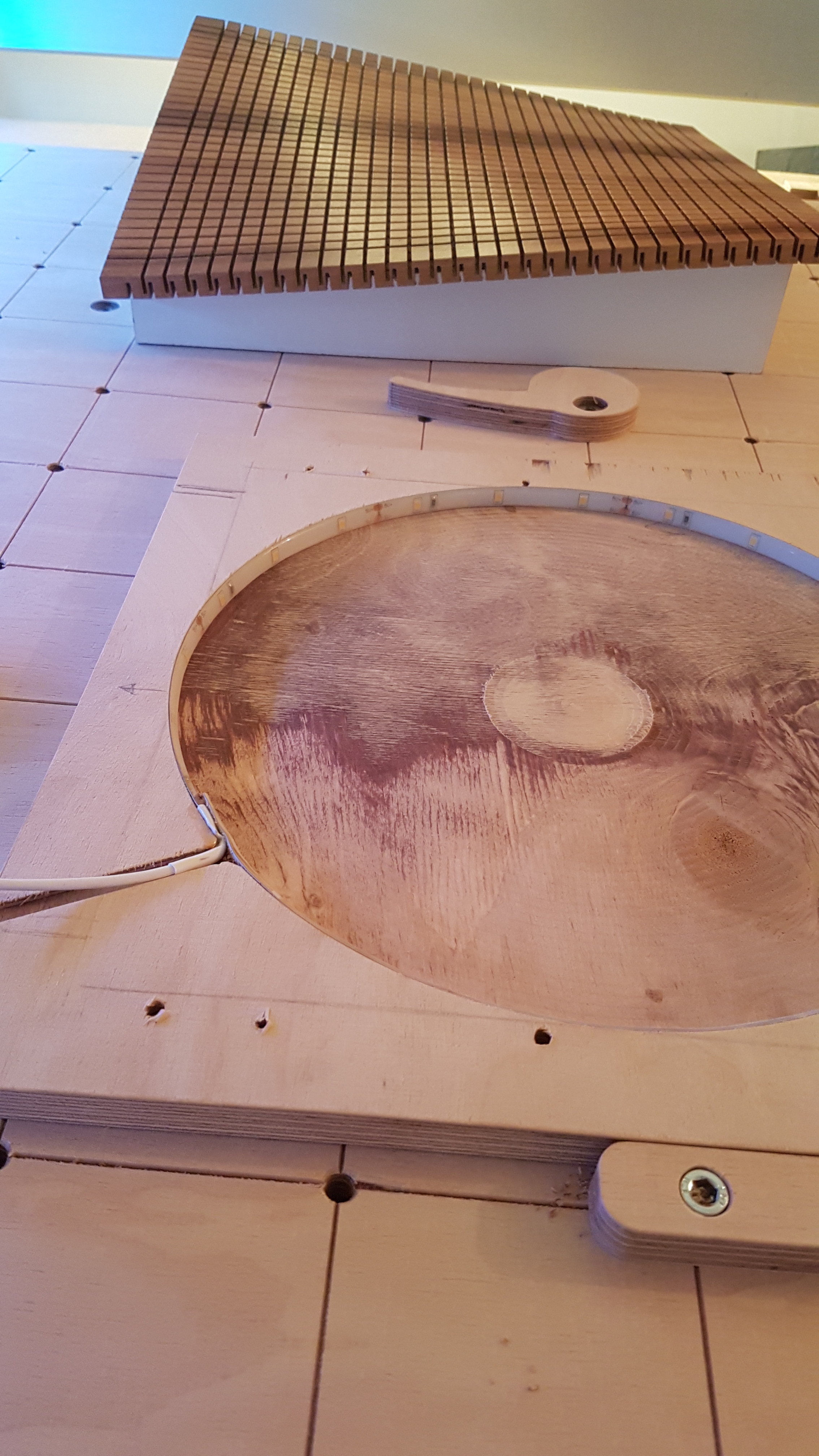
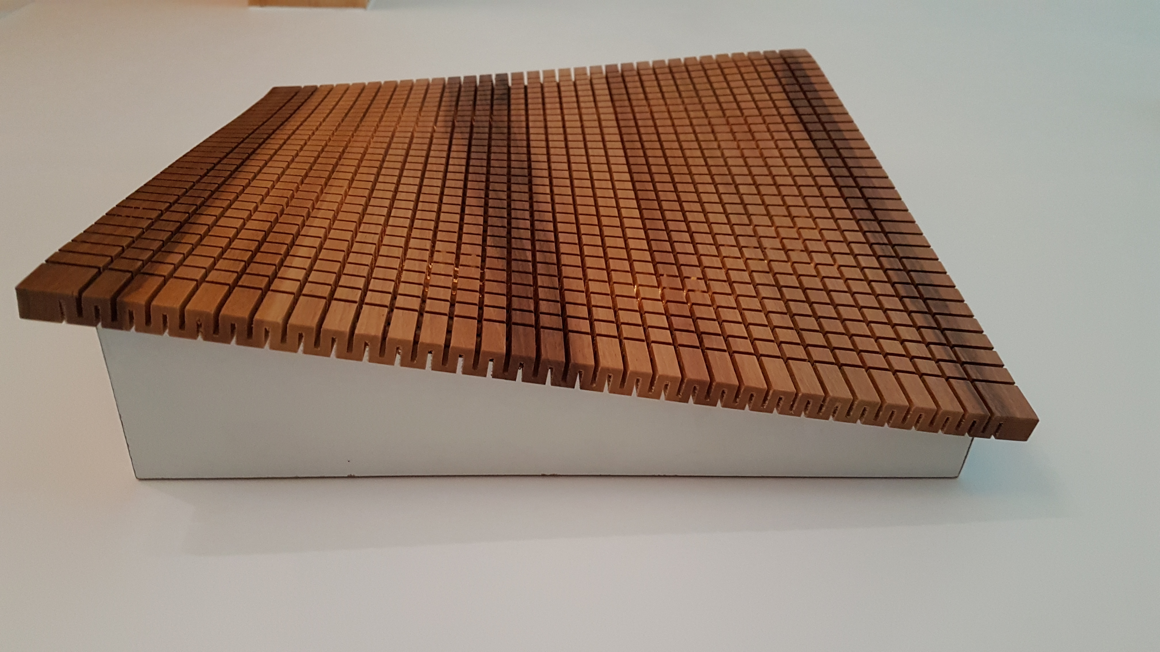
the frame is in 3mm medium, “soft wood” in walnut. I made all the drawings on rhino, and made the machining on CC.
plancher tordu.c2d (772.3 KB)
ossature1.c2d (204.6 KB)
ossature2.c2d (203.6 KB)
recto.c2d (112.7 KB)
verso.c2d (115.2 KB)
12 Likes
Very cool !
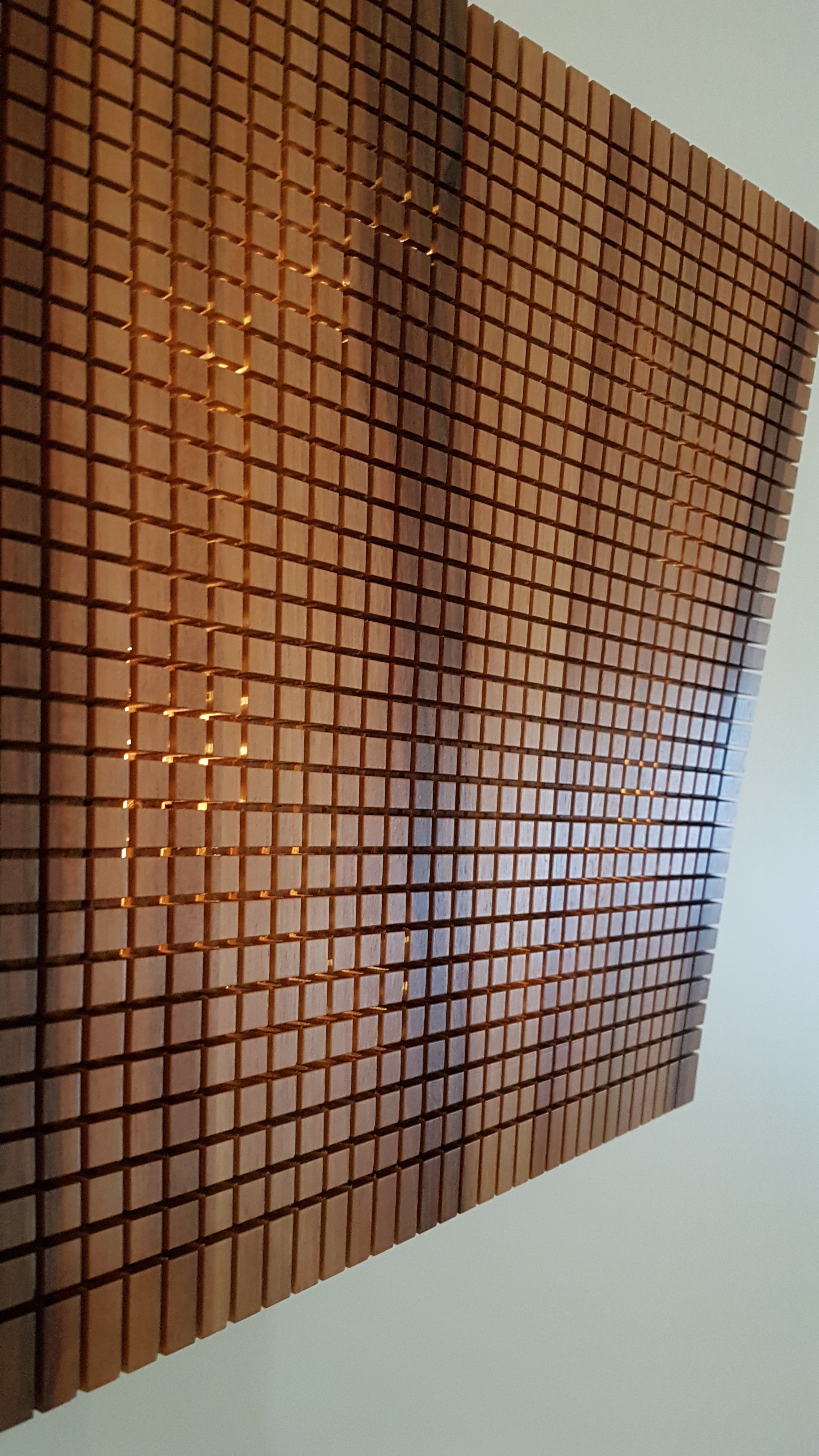
I am most definitely stealing this idea for making flexible wood surfaces:

Thanks for your entry Vivien.
3 Likes
fait attention de ne pas faire une forme trop cintré… le bois a une limite…
1 Like
et tu peux te servir de ton laser.
Here’s the file that includes setups and tool paths for the clamp that’s a part of the project that I posted above.
clamp v1.f3d.zip (361.3 KB)
Unfortunately, I couldn’t include the remaining components, however the technique used in this sample was used to create all the other parts as well. It’s mostly combination of very simple contour passes and adaptive clearing for the pockets. All the parts that I’m designing are meant to be simple and easily machinable without the use of jigs. Which streamlines the process during prototyping stages.
For instance, the bottom of the clamp is actually flat, instead of being rounded, so that I can quickly put it in a vise and not mess around with soft jaws or indicators to make sure that it’s perpendicular to the z axis.
There’re two setups for the second side OP, that’s because first one is zeroed on the bottom of the part to surface the remaining stock left after first OP. The other setup is zeroed in the middle of the circle and at the top of the part. I’m using ‘center of the circle’ macro for this operation. Hope that explains why I made two setups named back 1 and back 2. This step could be avoided if I simply made a jig, but like I said this is simpler and quicker for me.
4 Likes
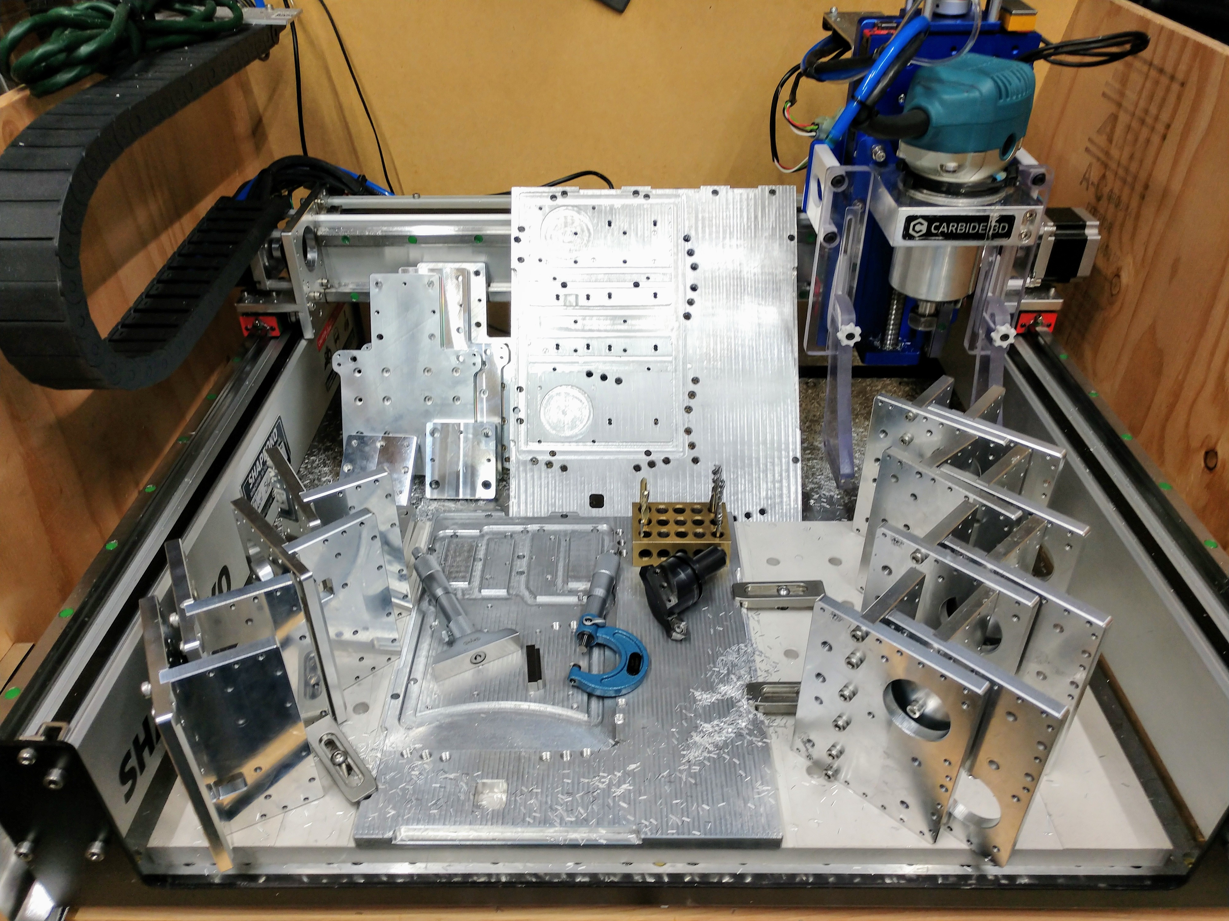
Not exactly the submission I was hoping to do, wanted something more “artsy” but just hadn’t had the time. So, I figure from seeing @BartK’s post, it encouraged me to just post what I have been doing, as it is 2D plates, that assembly in to a “3D” part. I have already shared the design files of my SO3 linear rail adapter plates but never really went into the CAM and workflow I go through. This is also the first time designing and using fixture plates (not just vises and drilling holes into my HDPE spoil board) to help develop faster and repeatable setup time (Typing this now, I am wondering if there is going to be a “fixturing” contest in the future from @Julien  )
)
Originally, I wanted to be able to machine two pieces of stock for the 4 (Y Axis) or 3 (X Axis) assembly parts, however I miscalculated how large of a fixture plate I would need and had to improvise a little. So I decided to move forward and just have the fixture plate multi purposed and machine the first set of parts, then re-setup with new stock to mill the second set.
There was at least three setups I needed to do, the first setup was the stock in its rough cut form (5.5" x 9") using fixture pins and side clamps to get access to the top for boring tolerance and threaded holes along with other features (dado joint and motor through-hole).
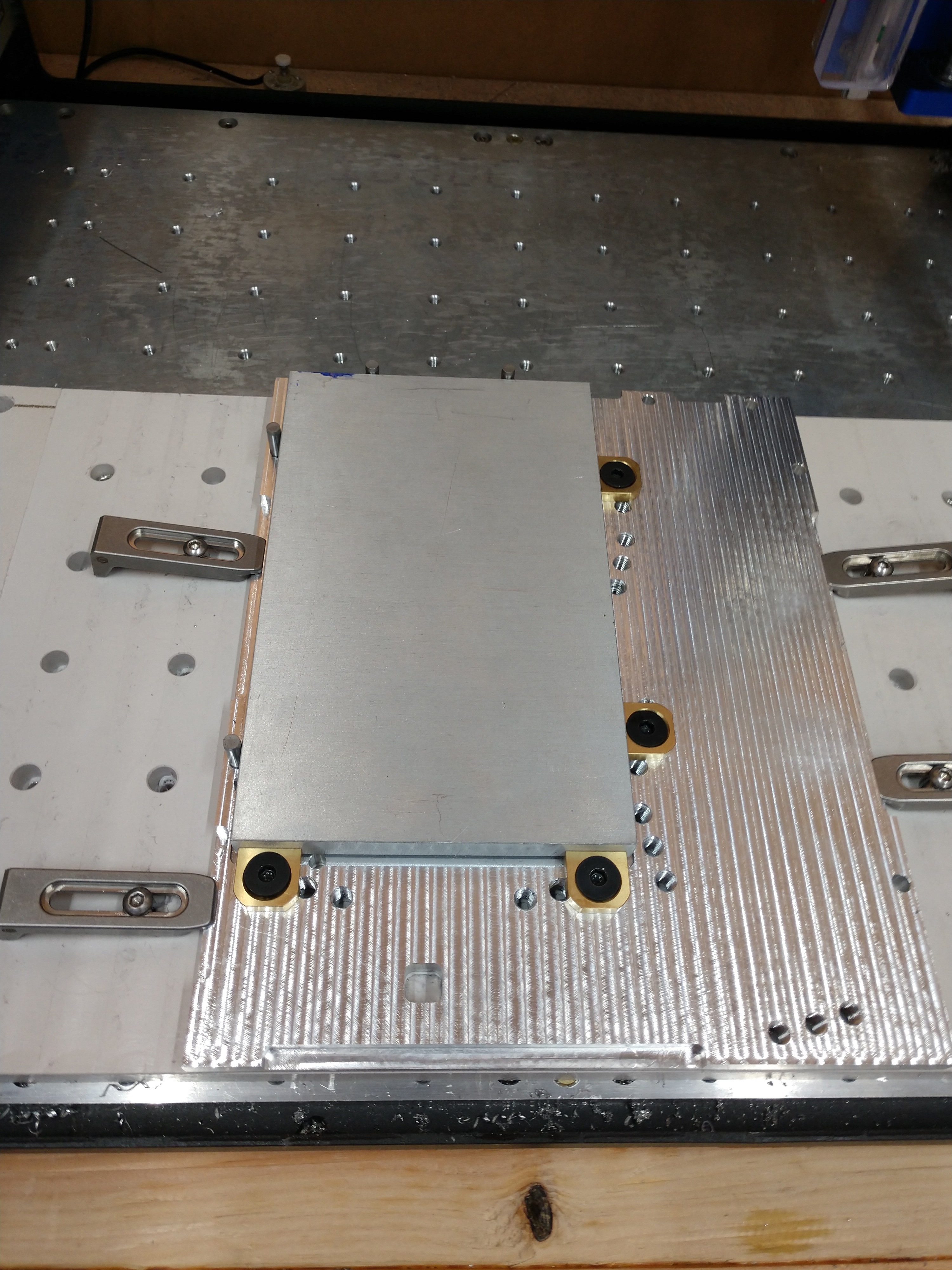
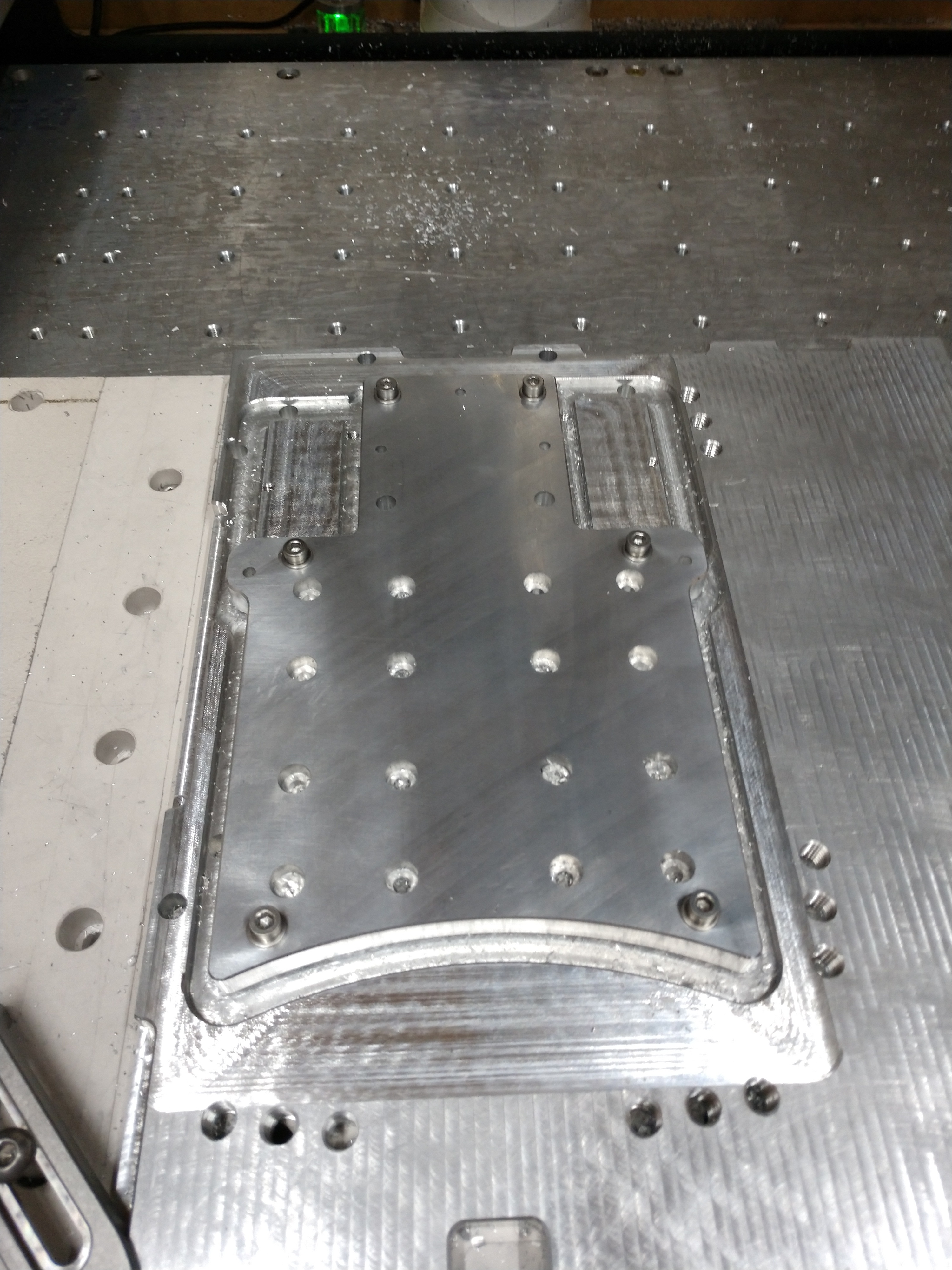
Second setup required getting access the sides to clear the stock down to shape. Using the existing features of the part, I created M4 thread holes that align with them on the fixture, so once features were cut they expose the mounting points to my next setup.


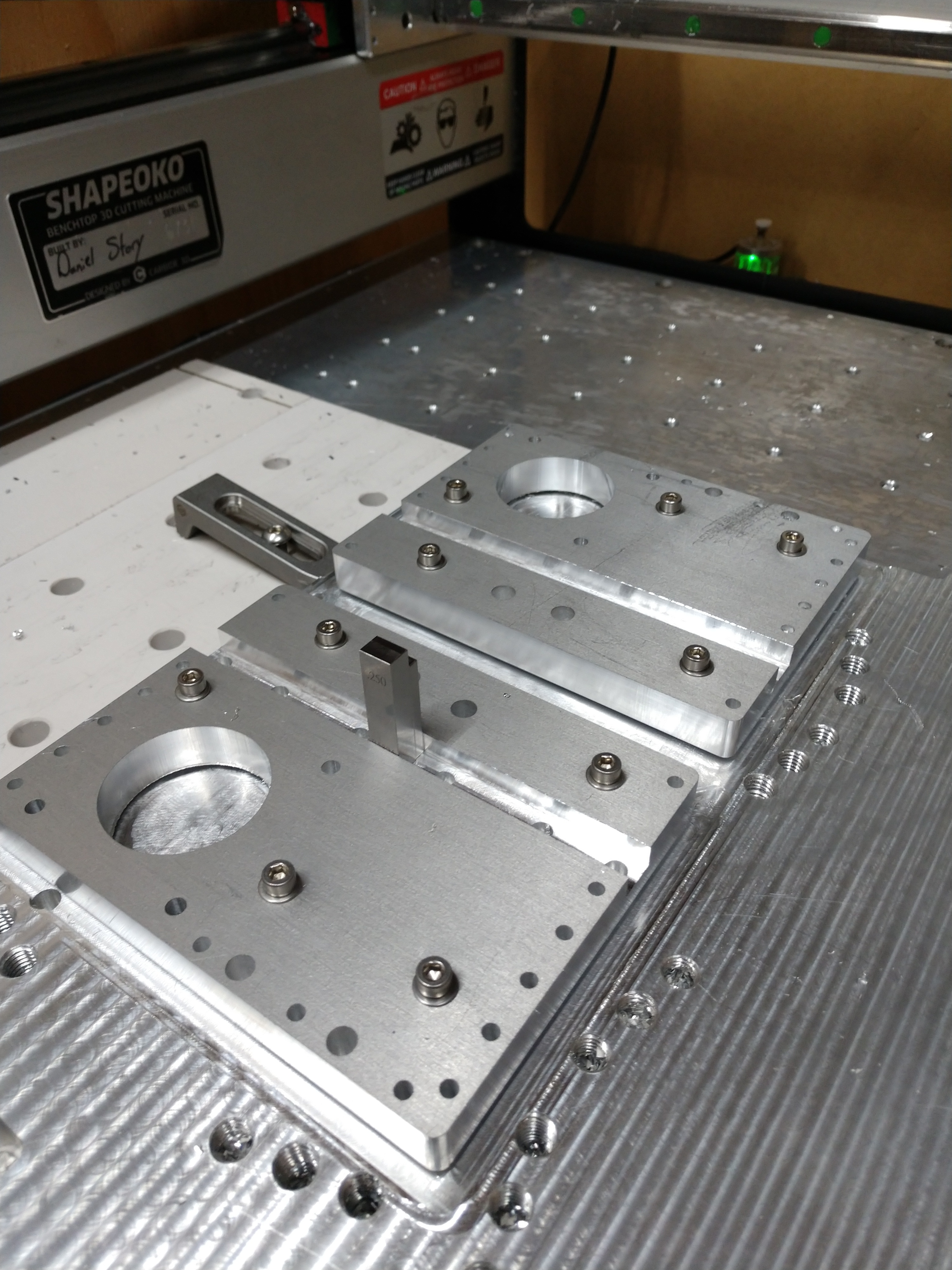
Third setup is to support chamfering the parts on either side, I used index pins to locate the part in its final form while still using the M4 threads to clamp the parts down, removing the pins before starting the g-code op.
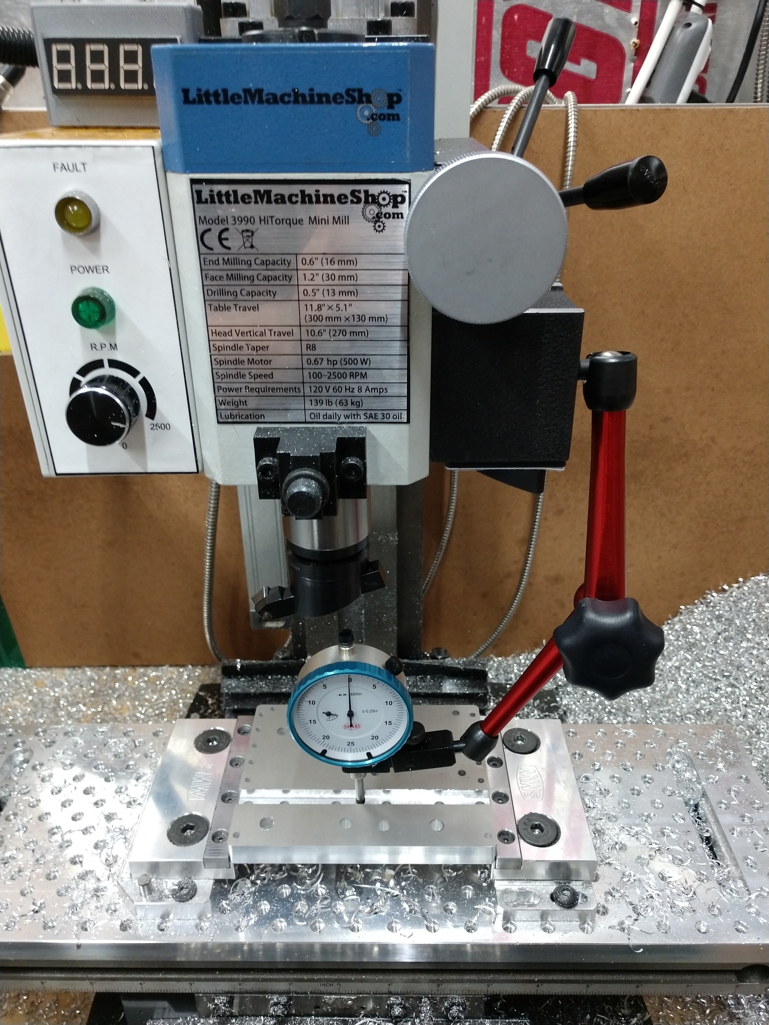
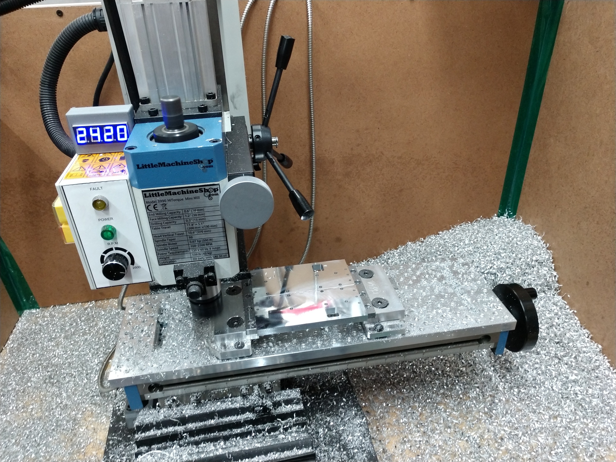
When it came to tolerances, I really don’t have them defined, as for one, I’m not a professional (I don’t know the best method to define them), and in a way it’s in the hands of the SO3 rail lengths and how precise the linear rails are mounted; let alone there is slop designed into the system. However I try to do my best to get as close as possible (<0.005") in the critical areas. To do so, I use gauge blocks and Fusion 360’s “Stock to Leave” to dial in the dado joint. I end up surfacing the Y plates (being typical 6061) to increase flatness and parallelism (indicating on the dado) using a fly cutter on my benchtop mini mill (hope that’s not disqualifying :P). ATP-5 stock would help alleviate this process (though I believe it’s flatness spec is 0.015" at this thickness). I then surface the joining plate until they fit into their paired counter part.
All said and (almost) done, it was quiet the journey filled with frustration, pain and eventually love and happiness
The Y fixture and CAM was my first attempt and just is a mess with weird setups from in-progress fixes, etc. The X fixture is a better example too look at and base off
Linear Rail Carriage Plates
Y Fixture
Y Extrusion Plate CAM
Y Carriage Plate CAM
X Fixture
X HDZ Plate CAM
X Motor Spacer CAM
12 Likes