Thank you for the cheat-sheet graphic. I’ve seen you share it in a few threads but I’m still having trouble figuring out the parameters to use to get tight joints. I did a number of successful v-carve inlays in Vectric’s V-Carve Desktop back in 2019 and 2020, and when I saw that Carbide Create now has an inlay plug mode, I decided to give it a try and dive back into inlays.
For my female part, I set the depth to .15" and used a 60-degree V-bit and 1/8" clearing bit. For the male part, I set the plug depth to .13" (to leave a .02" glue gap") and the top gap to .04" for the saw/clamp gap. Is this incorrect? Are those two numbers supposed to add to the female depth? I don’t remember what settings I used to use back in Vectric VCarve and no longer can run Windows software on my Mac, but I’ve watched a handful of videos recently and the recommendations vary a lot. Howard Boehm’s Vectric tutorial suggests 2/3 of the female depth for the Start Gap (Plug Depth in the Carbide inlay plug mode?) and 1/3 for the Flat Depth (not sure if that has an exact equivalent in Carbide’s parameters?).
For clamping, I just put 100 lbs of weight on top the plug and left it overnight (with a 1/2" piece of acrylic to spread out the weight). I realize that’s a lot less PSI than a hydraulic press or a book clamp, but when I did inlays six years ago, I don’t remember using huge amounts of pressure.
The good news is that it worked and I really like the tray, but it took a lot more work to get it there than I remember. Looking closely, there is a gap about .5mm around some of the letters where either the female pocket was too big or the male pocket too small? I tried filling those in with glue and sawdust, but it didn’t make it look much better, so I hoped the polyurethane and wax would hide it mostly. I wish I had more in-between pictures to better show the issue.
To improve this for the next one, are there better parameters I can use, or do you think I need to up my clamping pressure, or should I offset my male or female vectors slightly?
I very much appreciate all the help and advice you and others put in to these forums. I bought my Shapeoko 3 back in 2015 (serial #1087) and this has been such a friendly and helpful community for more than a decade!
Pocket Depth: 0.150
Plug Depth: 0.050
Top Gap 0.150
Once cut, measure the pockets at the top surface. If they’re a bit larger than 2", there is some slop or runout causing them to cut oversize.
Assemble them & measure the top gap & glue gap.
The difference between the programmed & actual values will give you a “fudge factor”
Apply that fudge factor to your desired depths.
Thanks, Tod. I’ll give that a try and report back.
Although I’m still trying to figure out what the software actually does with the values for Top Gap and Plug Depth. I apologize if I’m just being obtuse or this is too much to explain in a forum.
With a female pocket - a regular old fashioned v-carved valley - I think it creates a tool path where the v-bit goes right in-between the two vectors, plunging up and down as needed to hit the the two vectors based on the angle of the bit, and without exceeding the max depth. If the vectors are too close together or the bit angle is too shallow, the valley won’t be as deep as max depth. Conversely, if the bit angle is too steep or the vectors are far enough apart, it may wind around the sides separately to create the valley and then use a straight bit to carve out the flat middle part. If that’s all correct, then I understand the female part.
And for the male part, it’s doing the same thing upside down, right? So the plug depth plus the top gap is the total height of the mountain it leaves standing in the stock? If that total is less than the depth of the female part, how does that create a glue gap? I understand that if it’s greater, it would bottom out (i.e. no glue gap) and the excess height would create a saw gap, but I don’t quite see what about the angles causes the parts to collide before it bottoms out, or how to set those correctly to control that at least. I assume it has to do with plug depth and top gap (or start depth and max depth in the other terminology), but I’m not seeing how those values are picked to create those gap sizes.
(I actually used to be quite good at math and computer graphics, so maybe I’m just being slow in my old age. )
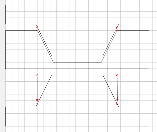
In the top drawing you can see how the male fits into the female. The red circles represent the vector that is being traced. For the female, the vector is on the top surface. For the male, the vector gets projected down to the Plug Depth. On the female, the bottom of the pocket is smaller than the vector, so accordingly, the top of the male has to be smaller as well.
The gap below the point where the vector gets projected is the Top Gap. It will be on top when the male is flipped over for assembly. The Glue Gap is the difference between the female depth & the male Plug Depth.
Thank you, thank you, thank you. This is exactly what I needed. The software is projecting the original vector down into the male stock, which is why it’s called Start Depth in VCarve and non-inlay mode. (I remember it seemed odd to me that the “starting depth” was below the stock surface when the bit obviously has to first cut through material to get there. But I think I understand it now, and also why Carbide3D tried to simplify the terminology.)
So the Plug Depth + Top Gap is the total depth that the bit will plunge into the male stock. The Plug Depth is how much of that mountain actually will sit inside the valley, and the Female Depth - Plug Depth = Glue Gap.
So in your 2" circle and square calibration tests, you suggested:
Pocket Depth: 0.150
Plug Depth: 0.050
Top Gap 0.150
That means before flipping over, the male mountain will sit 0.2" proud of its remaining stock. Once it’s flipped over and inserted into the .15" deep female pocket, only the first 0.05" should fit inside the female valley, leaving 0.1" of glue gap below and 0.15" above the female stock for the saw gap. Hopefully I’ve got that all right. As soon as I make these cuts I’ll cut them in half to look at the cross section.
You got it!! The reason I left the gaps larger is because in reality the plug will most likely fit into the pocket further than designed. Measure this distance to predict what will happen in the future & use it as your ‘fudge factor’ for all inlays.
And the reason I do tests with the design hanging off the edge of the stock is so I don’t have to cut it in half. You can see the gaps from that edge.


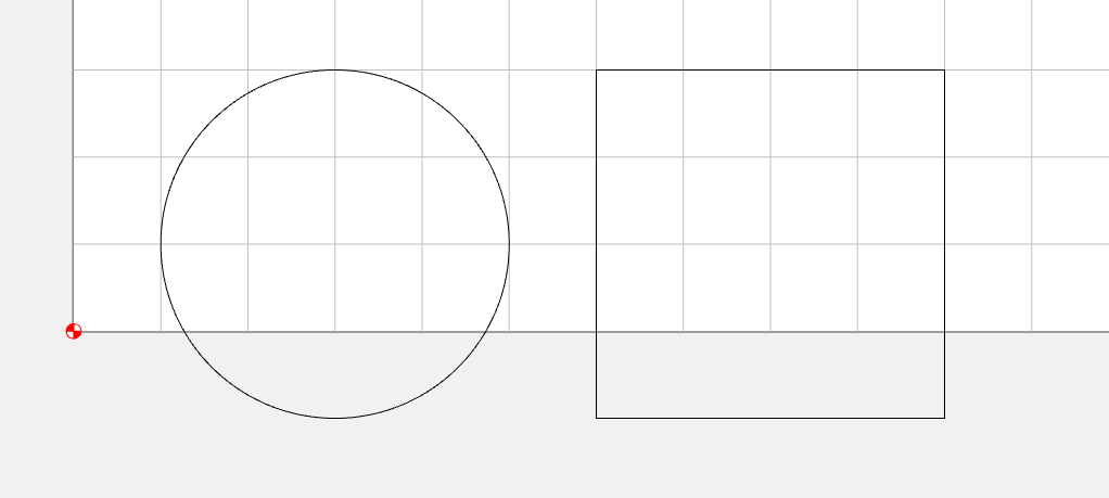
 )
)
 The reason I left the gaps larger is because in reality the plug will most likely fit into the pocket further than designed. Measure this distance to predict what will happen in the future & use it as your ‘fudge factor’ for all inlays.