Will I run into any issues if I connect both the JTech laser and my Spindle to the PWM pin on the GRBL board? I read that there are two PWM pins on the board that do the same thing but not to short them. Would it be ok to hook the JTech to one set and the VFD to the other or hook both in parallel or do I need to setup a SPDT switch to change between VFD and laser control?
I asked J over at J-tech that exact question as I have the same setup.
J said that the signal into the laser module is optically isolated so the laser wouldn’t cause any issue. I’ll be testing out my setup over the next week to see what happens. Some of the parts I need to complete my build are due today.
I chose to keep a “manual” approach, of soldering a connector at the end of a pigtail from the controller, and connecting either the laser or the spindle at any given time. Yes, I know it’s not an answer to your question, just thought I would share. I did this to:
- save me the trouble of any potential concern of plugging both (99.9% chances of it not being a problem anyway)
- but mainly, to add yet another layer of security to my laser setup (no connection => no PWM => no laser). This is me being unreasonably paranoid, since the Jtech already has three barriers (key, on/off switch, and enable button if you wire it), but…why not.
This works for me because I don’t switch from one setup to the other very frequently.
1 Like
Just for peace of mind, I wired in a DPDT switch for the laser/IoT relay signal. I just mounted the switch on my panel next to my feed hold panic button.
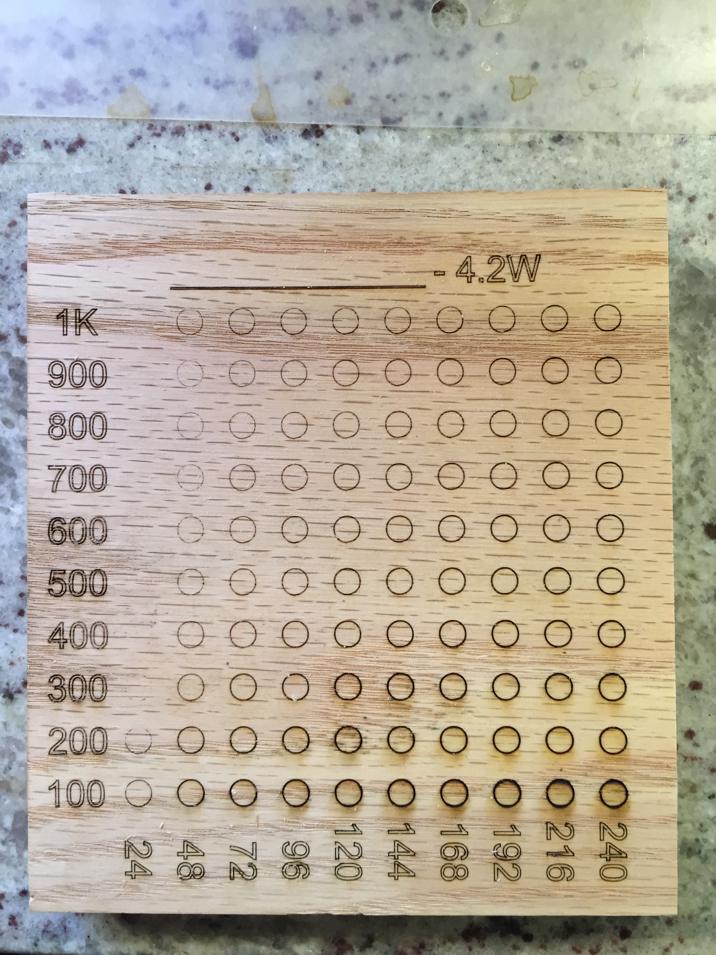
Here is a test with the PWM only wired to the laser. I’m going to hook it up again to the spindle and repeat the test to see if there is any variation.
I’ve wired the spindle input (VI & ACM) in parallel with the inputs to the J-Tech laser. I can report back that the Shapeoko PWM signal drives both happily. I just manually make sure I only have one powered on. Eventually my parts will arrive from China and I can build my electronics box that’ll do it automatically.
So you can wire them in parallel with no problems
4 Likes
Hope your Chinese parts dont come with a box full of corona.
1 Like
Why, I like beer, even beer from Mexico
Sure, the X Axis is the “spindle speed” which is really the PWM speed. My $30 and $31 are set to give me a minimum speed of 300 RPM and maximum speed of 24000 RPM. The scale is in hundreds (X100) of the RPM so it starts with 2,400 up through 24,000. I use those same setting for my VFD/Spindle and my Laser and the PWM signal is wired to them both in parallel.
The Vertical scale the Feed Rate in mm/minute. So 100 mm/min thru 1000 mm/min. I did modify my post processor to turn on Laser Mode ($32=1) so I never forget to do that. BTW, this was done in Vcarve using a Quick Engrave toolpath.
I have another edition of that pattern that fills in the circles.
Thanks … so based in this test model on oak wood (I presume) you can set the desired speed and laser power to get the results you want.
This topic was automatically closed after 30 days. New replies are no longer allowed.