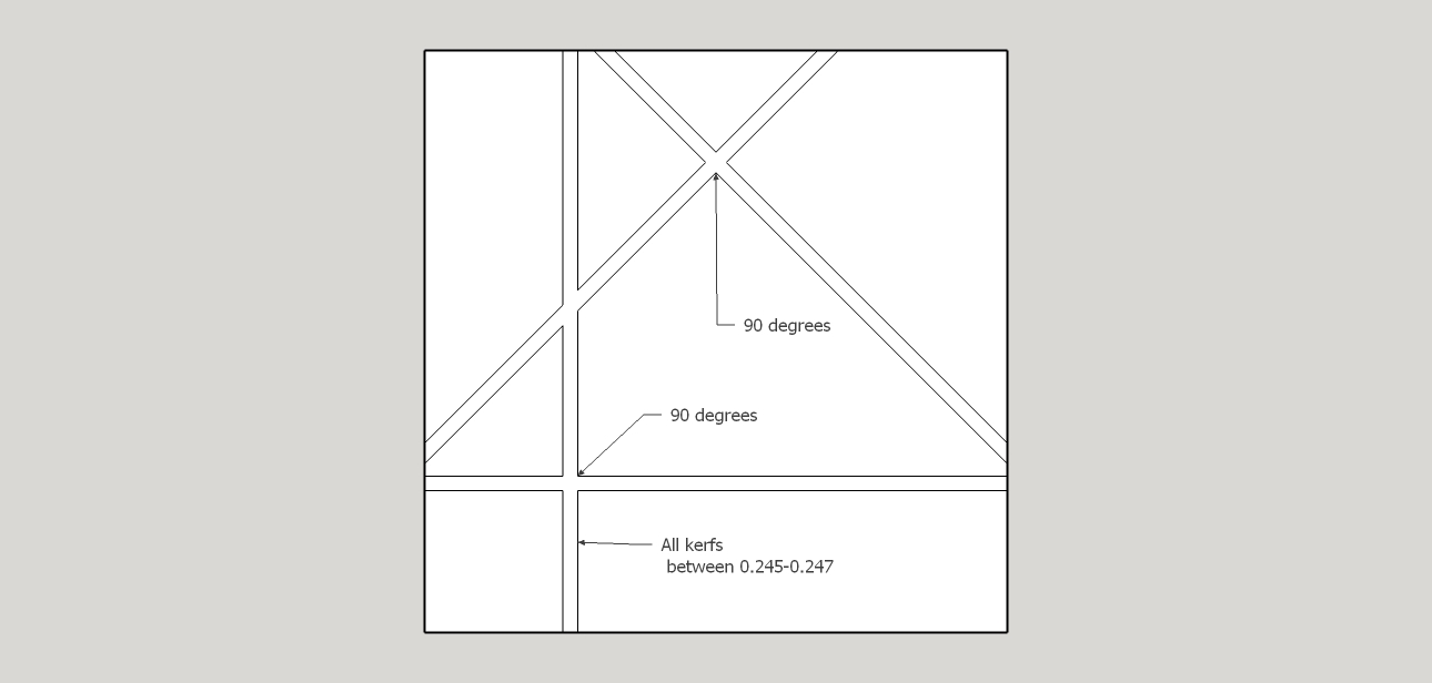
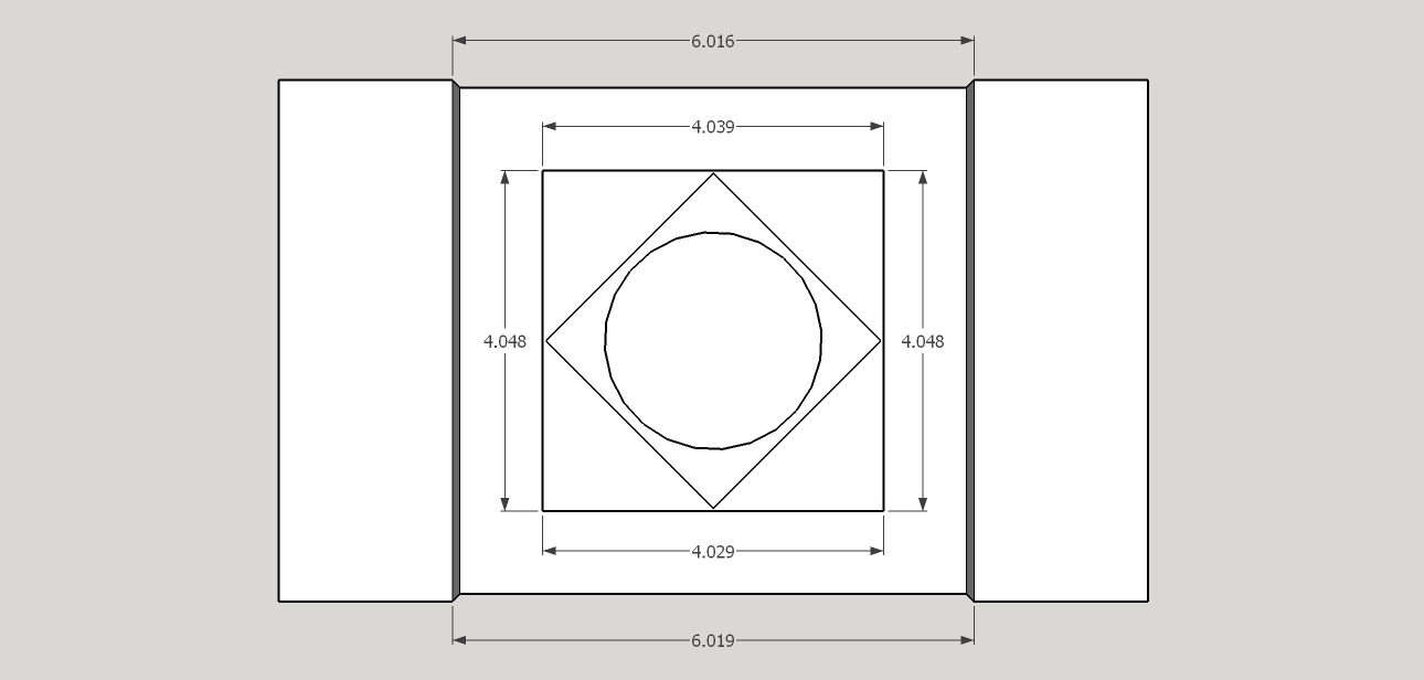
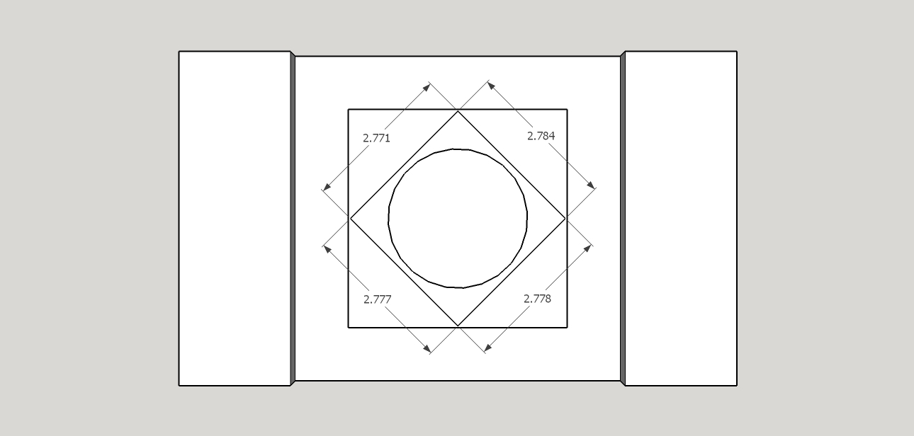
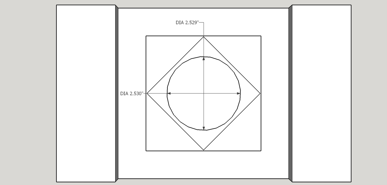
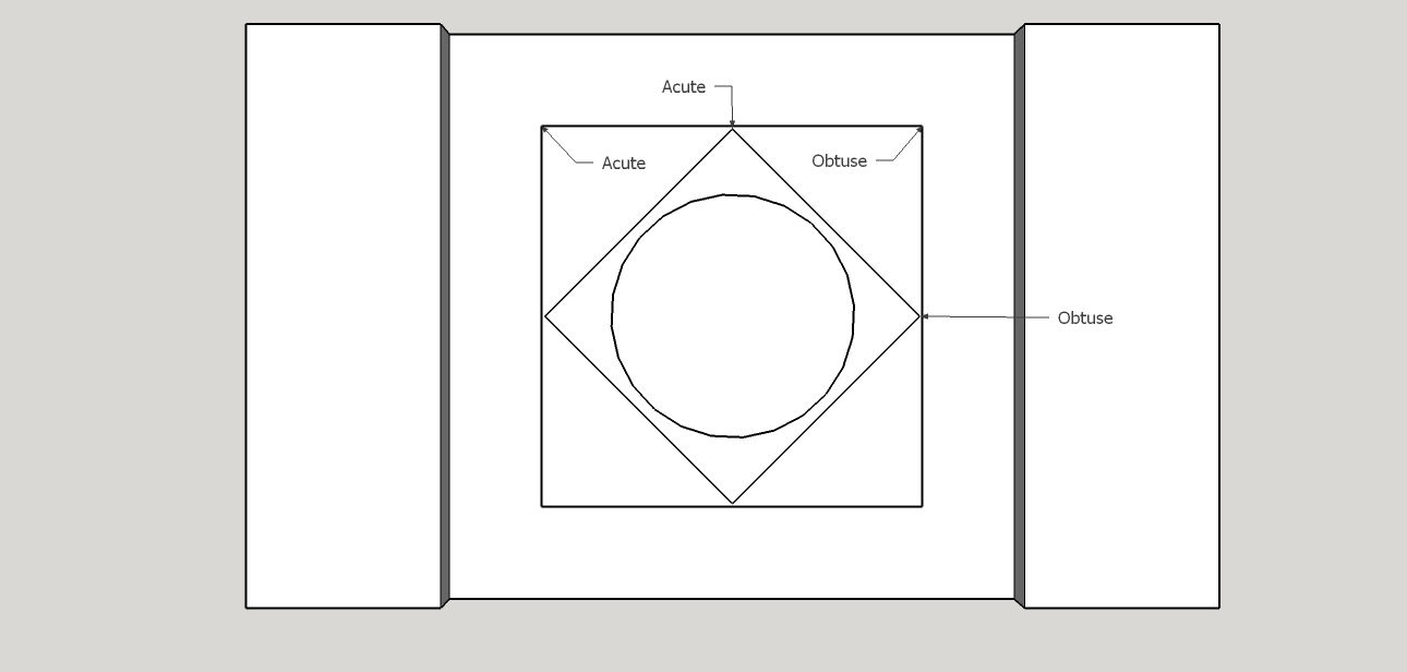
I’ve been trying to nail down repeatable precision and accuracy since I set up my XXL. I ensured the platform the Shapeoko sits on is flat and level, as is the machine itself. The extrusions are as square as I can seem to get them, done by both pulling the X axis to the ends of the Y extrusions while the bolts holding the endplates were loose and then tightening them and also by measuring corner to corner and adjusting. I ran a number of X,Y,Z movement tests with a dial indicator, adjusted the steps per those calculations and still was off. I ran a number of three circle/belt stretch tests and was finally able to get the inside diameter of the circles to within 0.001 of their intended diameter, but then the distances between circles was too much. So now I’ve run a runout test by making passes left-right, top-bottom, and 45 and 135 degrees. That one went well, with all kerfs being square or 45 degrees to each other as they should be and I was surprised to find that the kerf was less than the expected diameter of the bit. (bit is supposedly 0.25, kerf was between 0.245-0.247). Then I ran a circle, diamond, square test and made some pictures of the measurements I got. The large square should be 4 x 4, the diamond’s sides should be 2.75 x 2.75, and the circle diameter 2.5". I can wrap my brain around what’s going on when dealing only with X,Y, or Z but when you start throwing in diagonals and angles, I get a little lost. Would someone mind helping me out to interpret what my machine is telling me I need to correct?
I think this method is a bit of a fool’s game. Too many variables (bit width, bit deflection, trying to accurately measure kerfs cut into wood using a set of calipers, it all stacks to problems).
If you were able to get accurate parts in one area of your machine previously by using the indicator method, but larger parts were inaccurate, then I’d suggesting finding a way to mount a set of digital calipers to your spoil board and running the same sort of test over larger areas.
Mr. Adams indicated that there can be uneven belt stretch and maybe that is what you’re dealing with. Maybe your left and right belts on the y-axis aren’t closely matched or stretched differently.
A 6" set if calipers would be a good start. You can get 12" calipers on Amazon for not too much money.
Oh, Fool’s games! Those are my favorite kind!..wait…
I have no problem not messing with this many variables if I don’t have to. My only problem will be measuring large distances to any degree of accuracy beyond reading a tape measure. A 12" caliper would be great but the XXL has a 33x33 work area and I’d like to test in on longer distances. Maybe the spaced dowels test I’ve seen others make would work.
Do you think I should input the kerf width of 0.246 into my tool library as the tool’s diameter, though? It seems to me that if the machine thinks the tool is wider than it really is, all my projects will be off.
Is this a cheap endmill?
004" is quite a bit off. If you want to be as accurate as possible then yes you should enter the actual size. But you also need to account for the tools runout in the collet which can be measured with a dial indicator.
How about measuring w/ the calipers a section of the 2 Y belts say a 4" section or however big a caliper you have, if they don’t caliper the same than you know you have odd belt stretch. Just a crazy thought from someone who thinks my machine is close enough for gov’t work. I’m gonna try it tomorrow on my machine just for giggles, I already know my z axis is 0.3 of a degree off of vertical but cutting 5mm plywood, I’m ok.
Do you think I should input the kerf width of 0.246 into my tool library as the tool’s diameter, though? It seems to me that if the machine thinks the tool is wider than it really is, all my projects will be off.
You want the effective diameter of the tool. If the collet is true (withing the limit of measurement), this is the same as the diameter of the tool, plus or minus a small bit, depending on the material you cut in. The easiest way to get this is run a few test cut in the target material and measure. This can be done a number of ways, and the result varies with the method used, since the effective size of the tool varies with the cut.
In simple terms, cutting a groove may give a different result than cutting a cylindrical bore or cylindrical pin. On a very rigid machine, the results should be pretty much indistinguishable. Once belts are involved, it is likely to vary a little.
I would probably run a few grooves of different depths (straight cut, just the tools width) removing and reinserting the tool between cuts, to get a good feel for the combined tool and collet runout. If the grooves all come in at the same (within measurement error, and with random orientation of the tool each time) width, then runout is not an issue. Figure that you should get within two counts on a digital caliper (0.001" or 0.02mm for a cheap chinese digital unit) for all cuts if there is no runout issue. Is this is the case, the measured width is your effective tool diameter for the material.
To calibrate the X and Y axes, I would directly measure travel. To do this, you can mount a dial (or electronic) indicator to directly measure motion of the machine (my preferred method), or make cuts in matching geometry and measure between corresponding edges of the cuts. For example, cut two parallel grooves with tool positions 100mm apart. Then measure between corresponding edges (for example, x positive edge to x positive edge of the next groove) of the features. This can be awkward with a standard caliper. This takes the tool diameter out of the measurement. If you are within the measuring tool tolerance, then you re good. If not, then you need to calibrate the travel of the machine.
Then, once both axes are correct, I would run cylindrical bore and measure the machined size versus the intended size. This will tell you the tool size for most applications, since the effective size cutting on one side (climb or convention matters here, by the way) will be different than when ploughing a groove. For example, run a bore of 50.00mm nominal, roughing at 49.9 (leave 0.05 for finishing) and a finish pass at the 50.00 size (for a 0.05mm finish cut). Measure the final diameter over several diameters, since the curve is, of necessity, a polygon approximation. If the mean of these is within 0.001" (0.002mm), you are dead on with the tool size. If the mean is low by 0.04" (0.10mm), your tool size is small by half of that (0.02", of 0.05mm) so increase the tool size spec and rerun the test. Why a bore rather than a pin? Arbitrary choice, as it is probably easier to measure in this application. If you do a pin, then the signs of the error change: if the diameter is low, the tool size is actually larger than you specified, so increase it in the configuration.
All of this said, I have rarely seen a case where the tool size (from a reputable supplier) was far enough out of nominal that it would need compensation on a Shapoko or a Nomad. The spec for the Nomad is in the ballpark of 0.04mm repeatability and 0.4mm/m overall, and the shapoko is not as tight. Even cheap, low grade imports cutters are closer than this. (This is not a criticism. To do better requires absolute feedback of position and/or MUCH higher precision drive with much higher rigidity and mass than these machines can provide. There is one or two orders of magnitude price difference to get there, plus the other issues that come into ply with a large, heavy machine). The low cost tooling I use in the Nomad is generally within 0.01mm, making the machine tolerance (+/-1 step for each position, due to rounding, and +/-2 steps for any relative position) at least as large an uncertainty.
A 12" caliper will allow you to test in three overlapping sections.
A 6" caliper would do it in six.
Either should be a quick way to identify any possible belt issues.
I’m going to set up my dial indicator to test the runout directly at the bit rather than indirectly through the kerf but this is a 0.25" Nomad Tools endmill that I bought from Carbide3D, so I assume it’s of good quality.
That’s a good idea, I’ll include that on the next test. I’m not looking for extreme precision but a part I tried to cut the other day that was supposed to be 15" long was off by more than 1/16".
That is some great information, thanks for taking the time to write it out. I’ll start working on those tests.
Just out of curiosity, what are your $100 and $101 settings right now?
Sorry, it took me a few days to sit down and check my settings. Currently, $100=40.240 and $101=40.268.
The types of calipers required could be a DML DC54150 or if you want something more durable you could look at Mitutoyo 500-196-30.