Creating Drawers

I definitely underestimated how much time it would take before I was ready to start making some drawers. I have some of my new shop furniture made now and I’m starting up on the drawers. I’m running into some initial issues of trying to get a single pass on the 1/4 in bit. Each of the smaller rectangles in this image are exactly .25" wide but after making a pocket or inside toolpath with a .25" bit, it always comes up empty. Is there a trick to get it to work when it’s exactly the bit width?

For my first attempt on these, I’m going to skip the cutout for the bottom piece and instead glue/brad nail it to the bottom. I might revise these later to include a 1/4 slot for the bottom as well. My front face is .25" taller so it won’t be visible. The main reason I decided to skip the bottom cutout is it would require me to flip the sides over to cut it, since it would need to be on the opposite side of the rabbet.

A given area of geometry has to be wider than the endmill (usual guideline is at least 10% wider) in order to fit.

Usual guideline for depth per pass is half the endmill diameter.

I ended up finding this other thread that’s trying to accomplish the same thing. They used a single line for the cutout instead of a square. Which makes a lot of sense after you figure it out. I tried that today and it seemed to work great. I’ll post some photos once I get a drawer or two done. I think this approach is going to work great for shop drawers.

1 Like

This topic was automatically closed 30 days after the last reply. New replies are no longer allowed.

It was asked:

How do I make a 15 x10 x 3 drawer using 3/4 oak stock

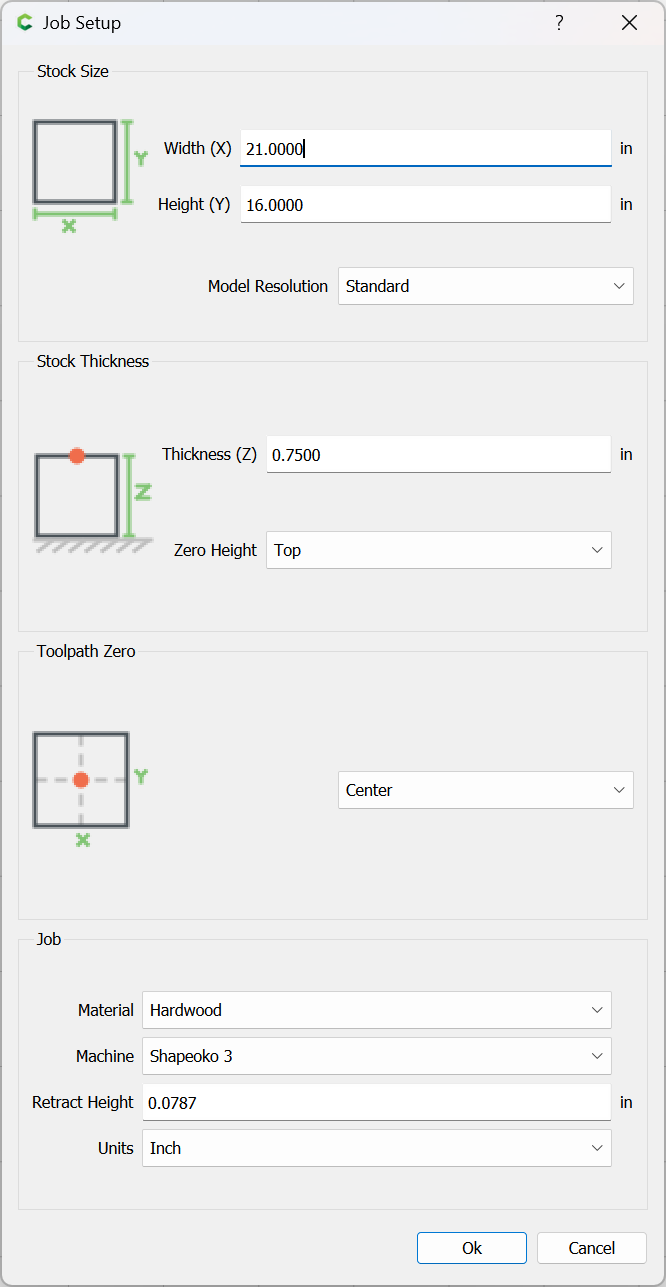
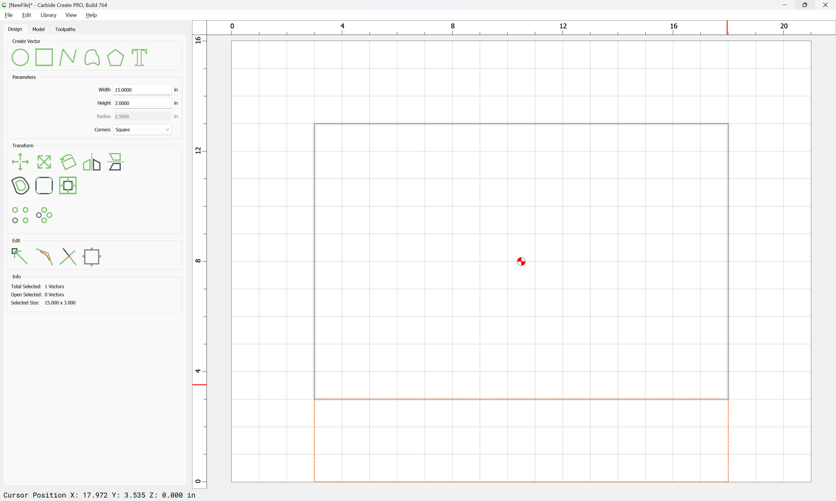
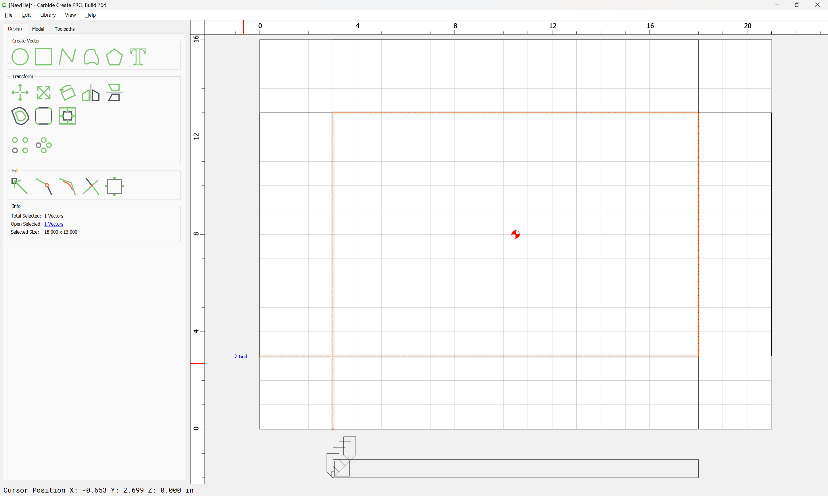
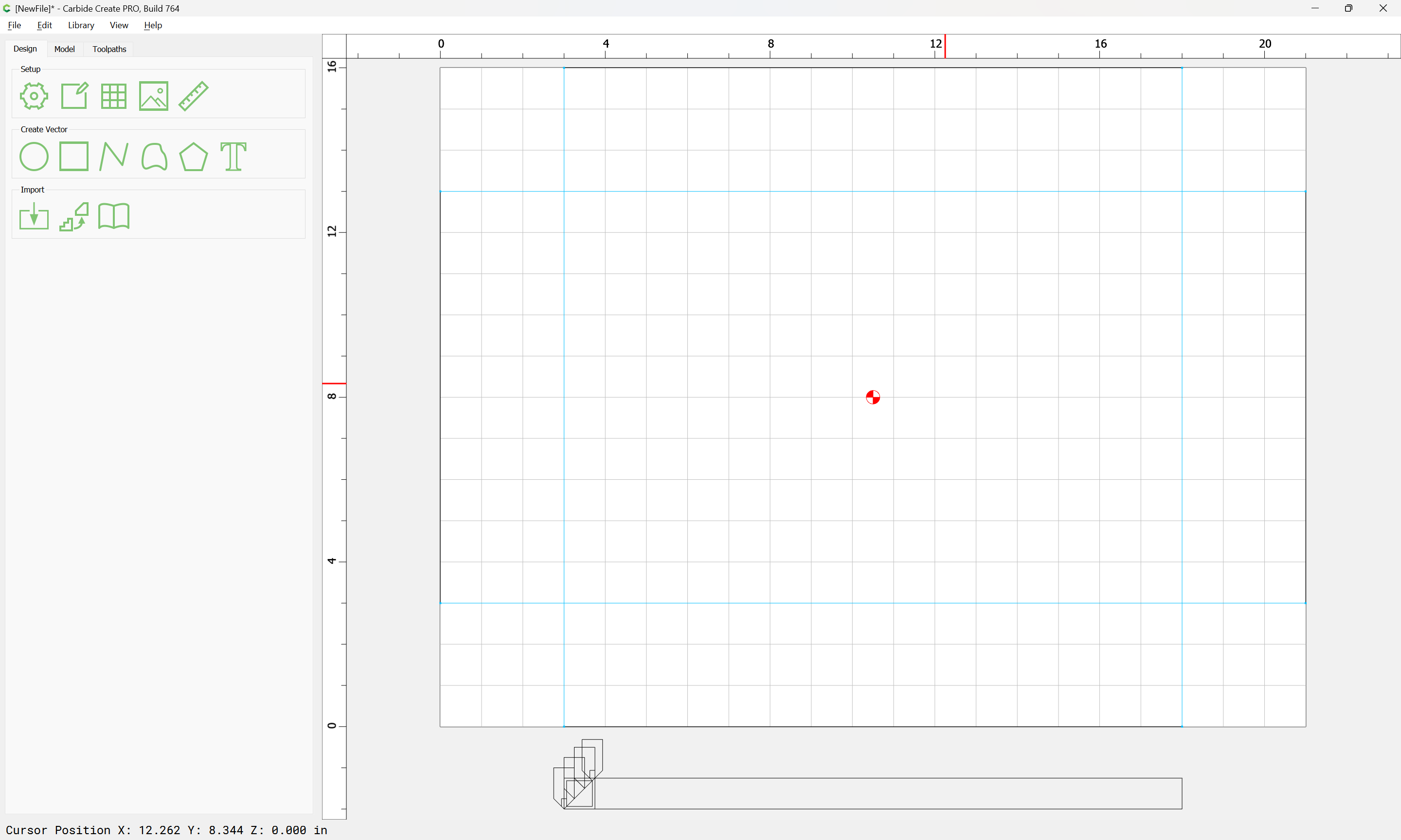
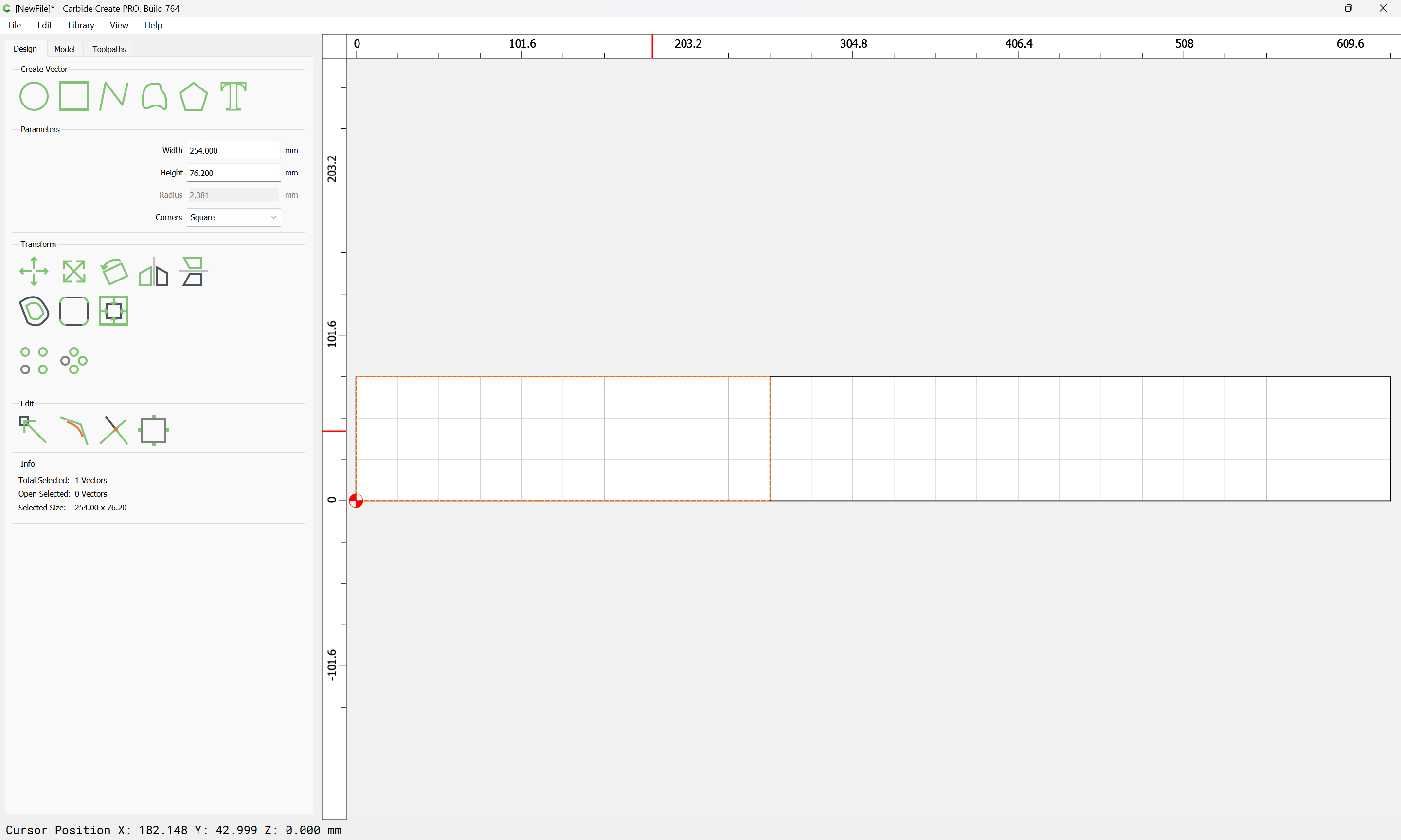
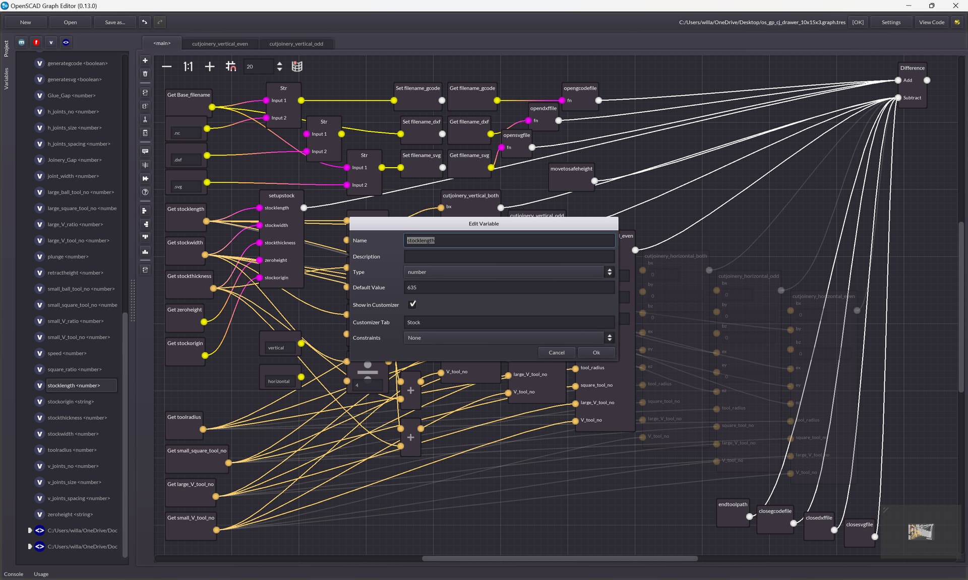
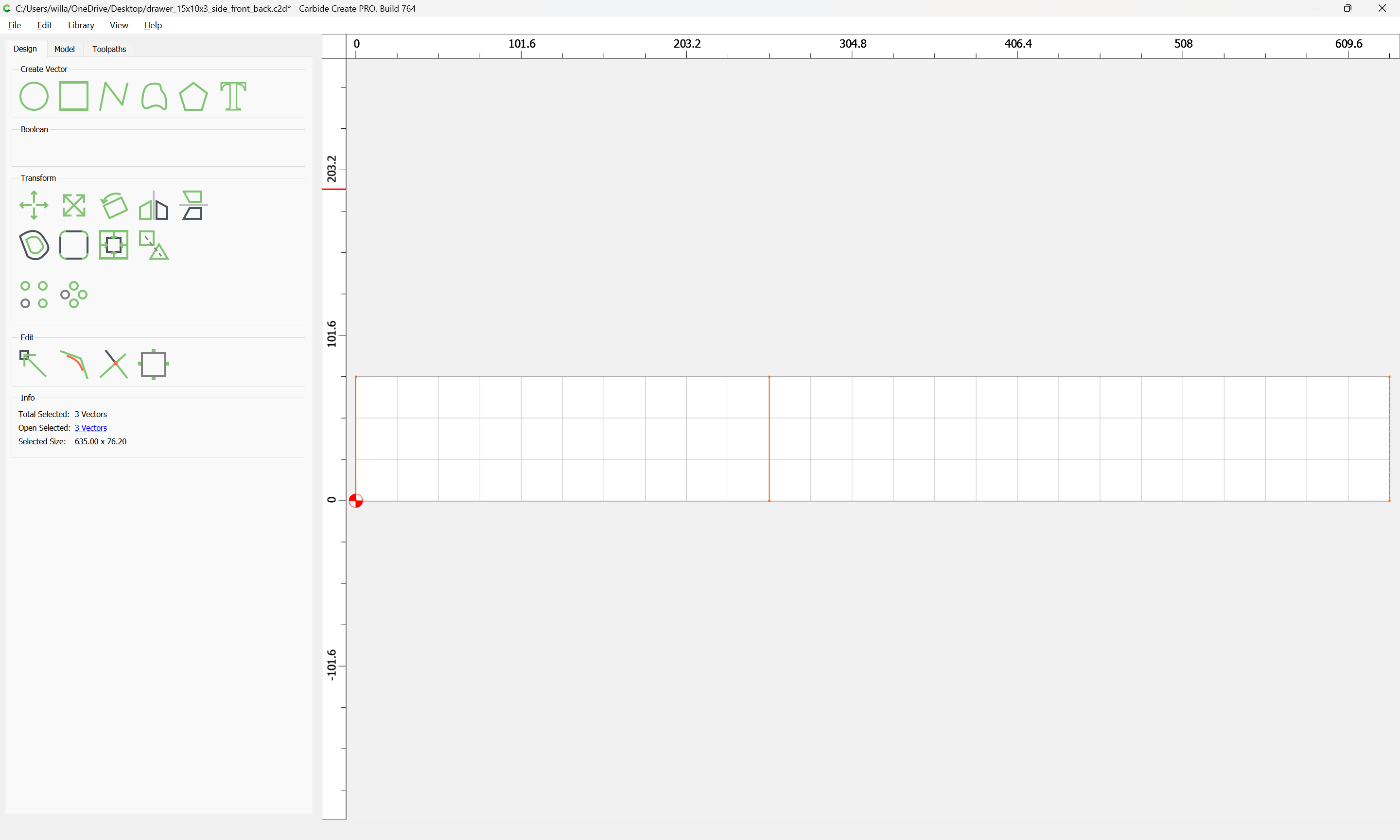
Trying to do this more simply, first we set up the stock size (we will assume cutting out of 3/4" thick plywood):

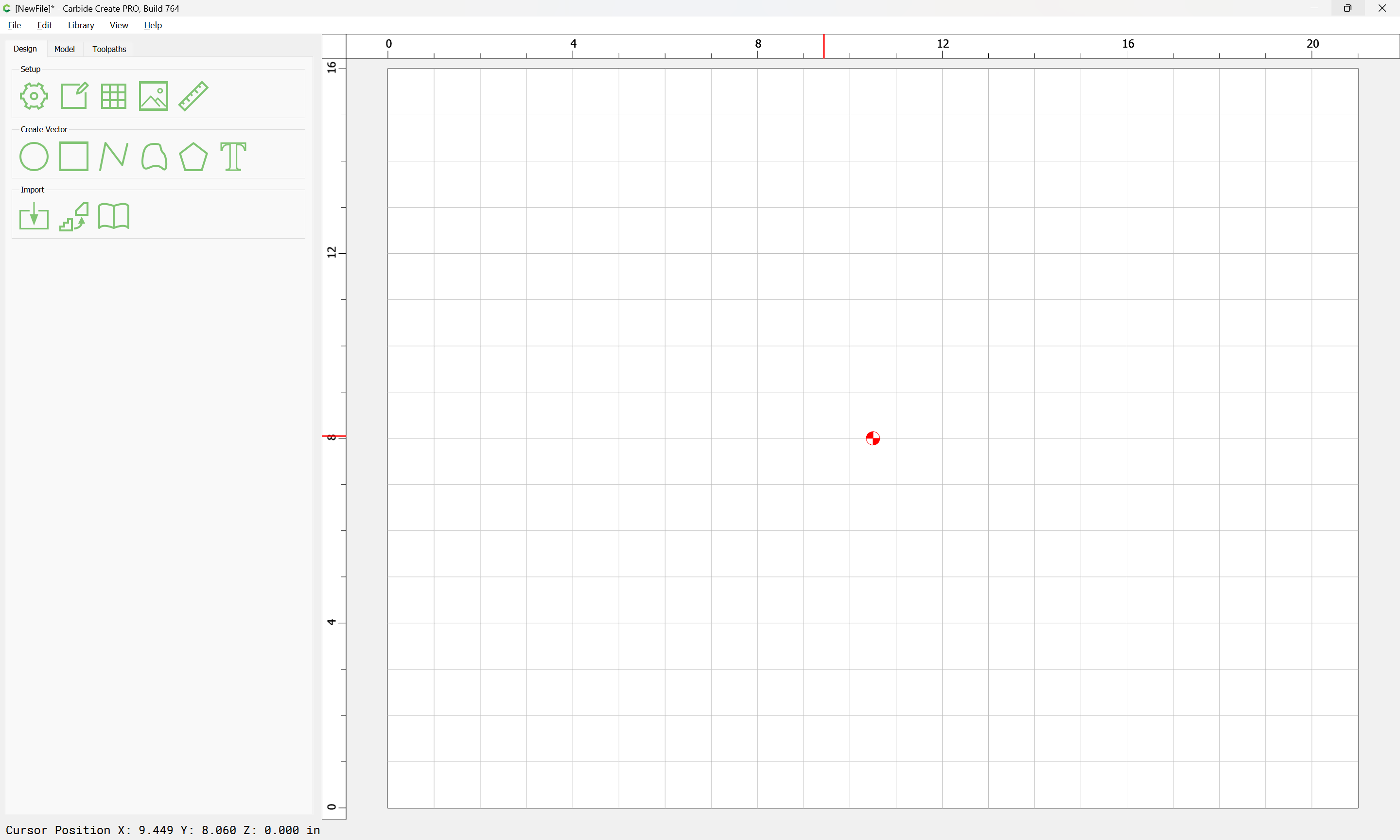
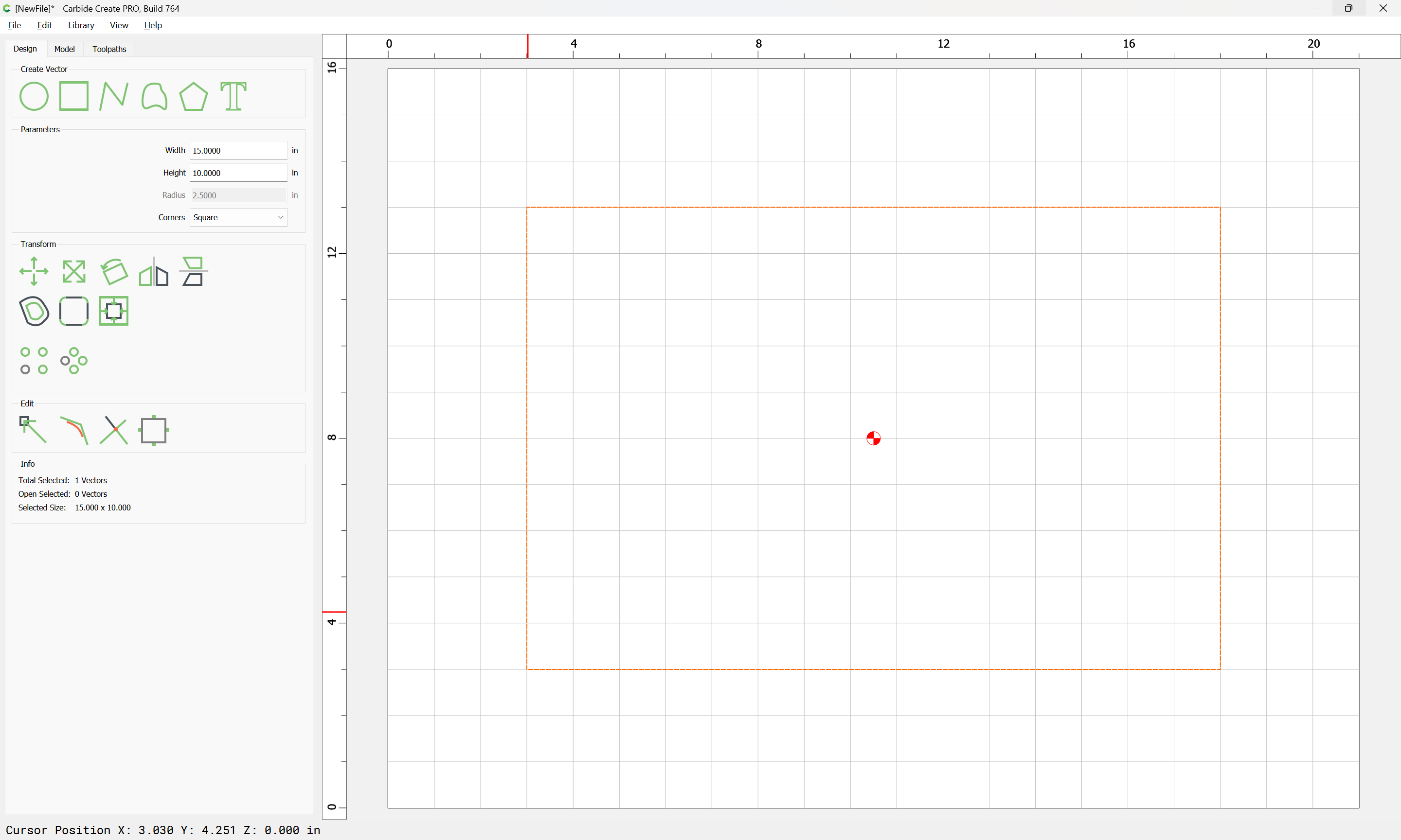
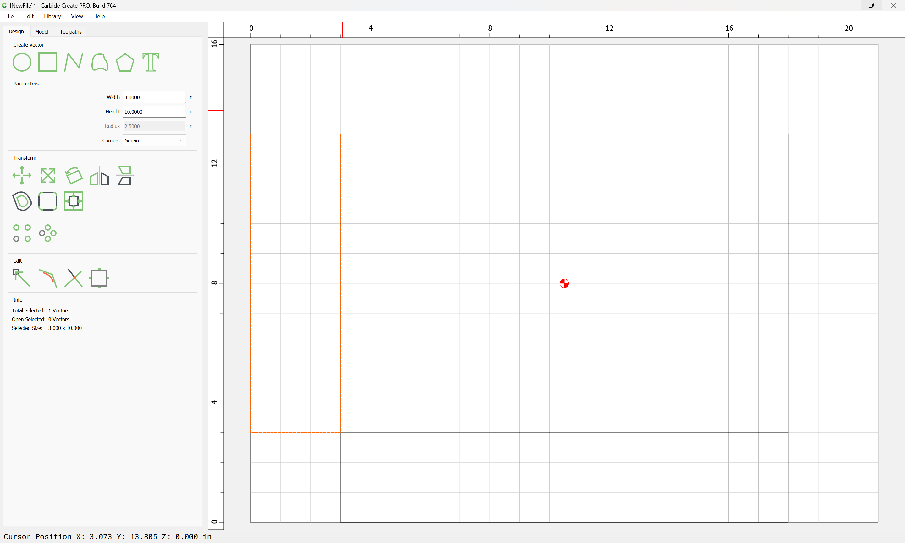
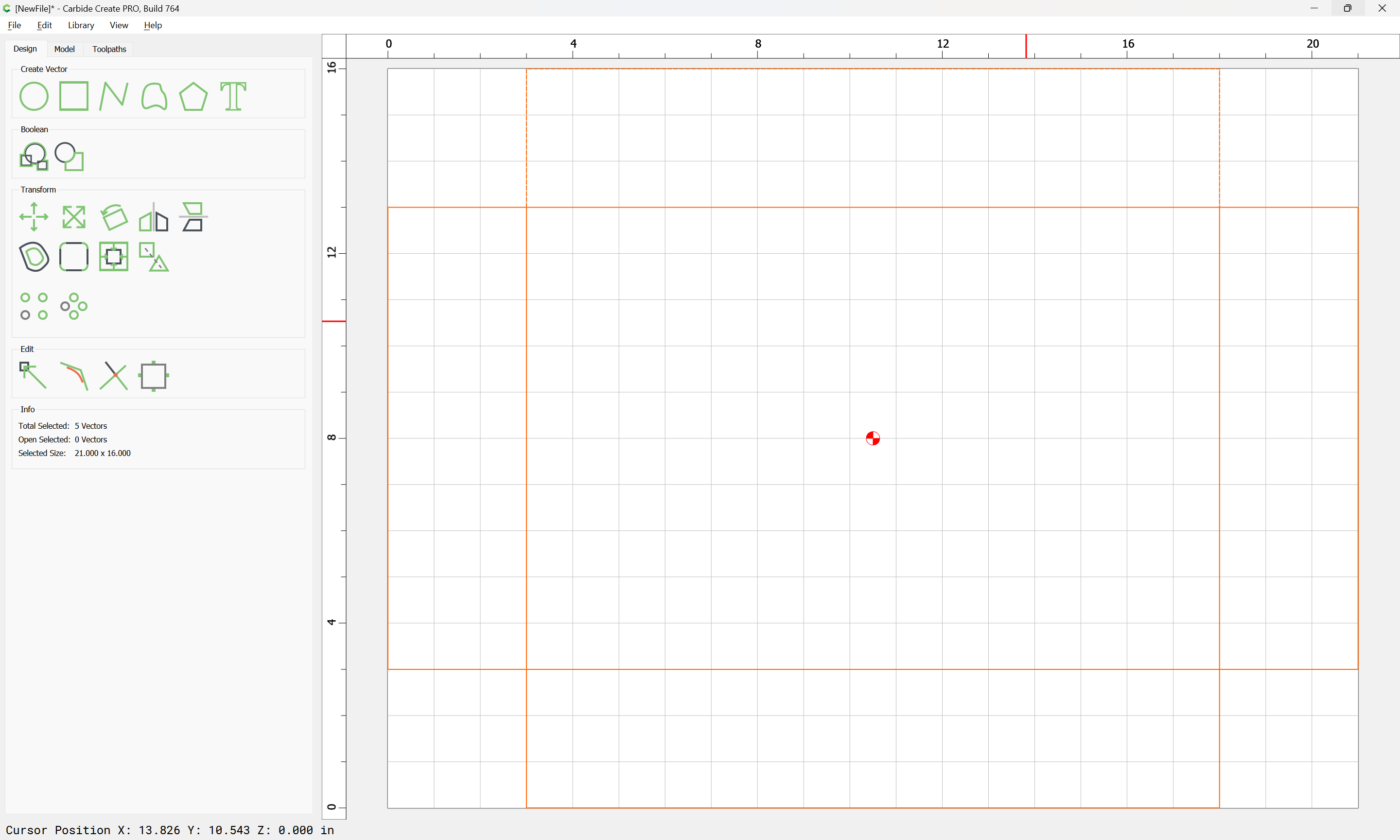
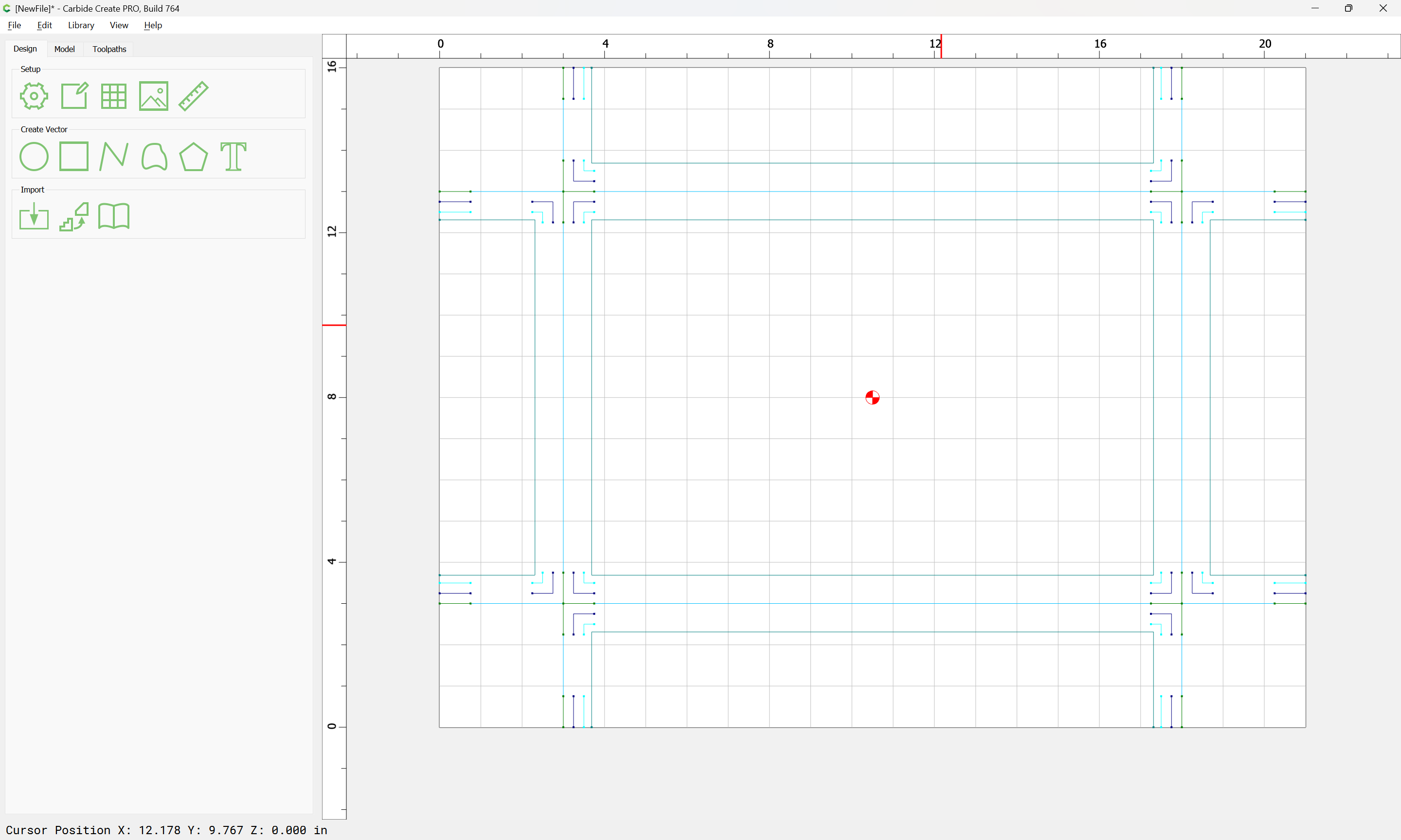
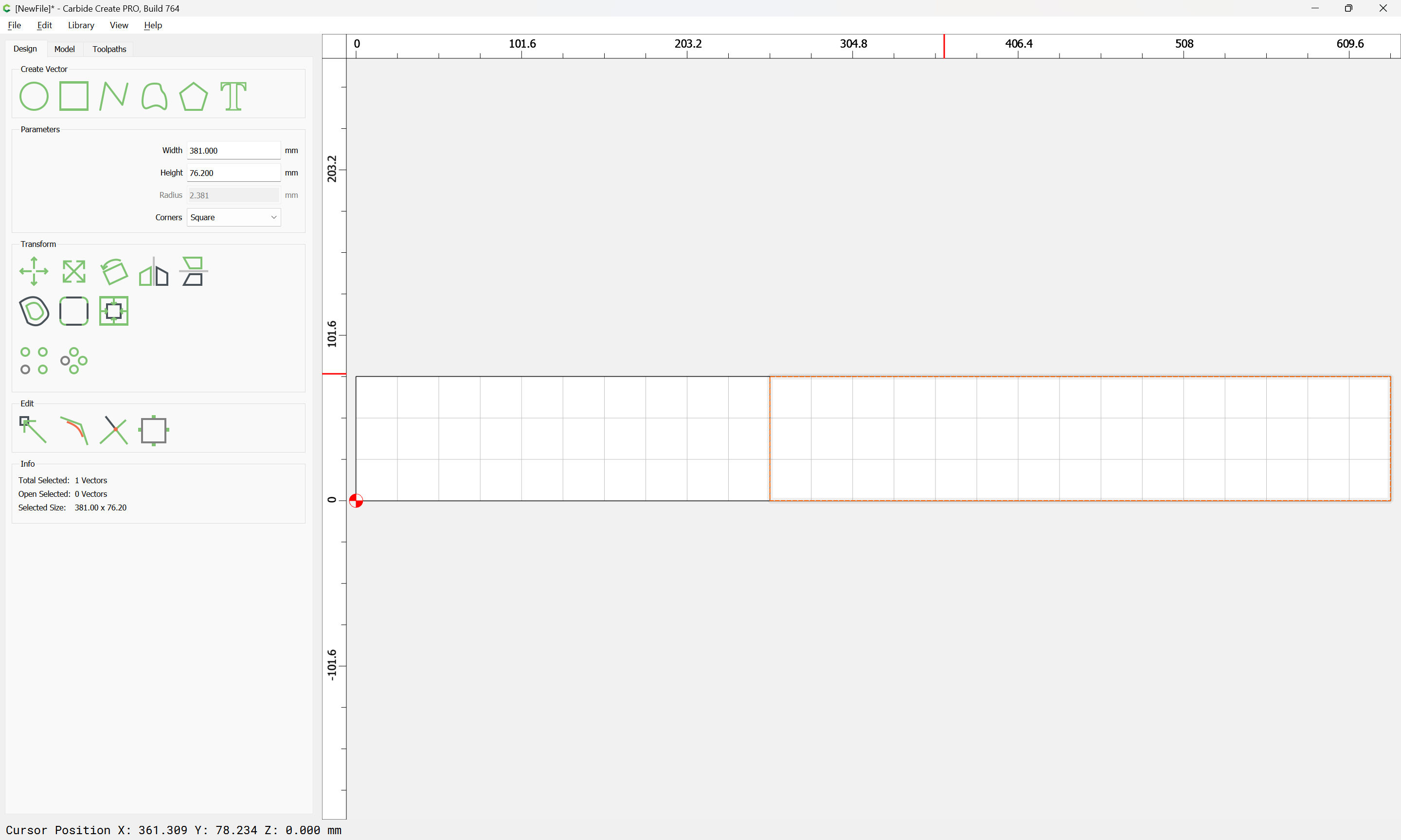
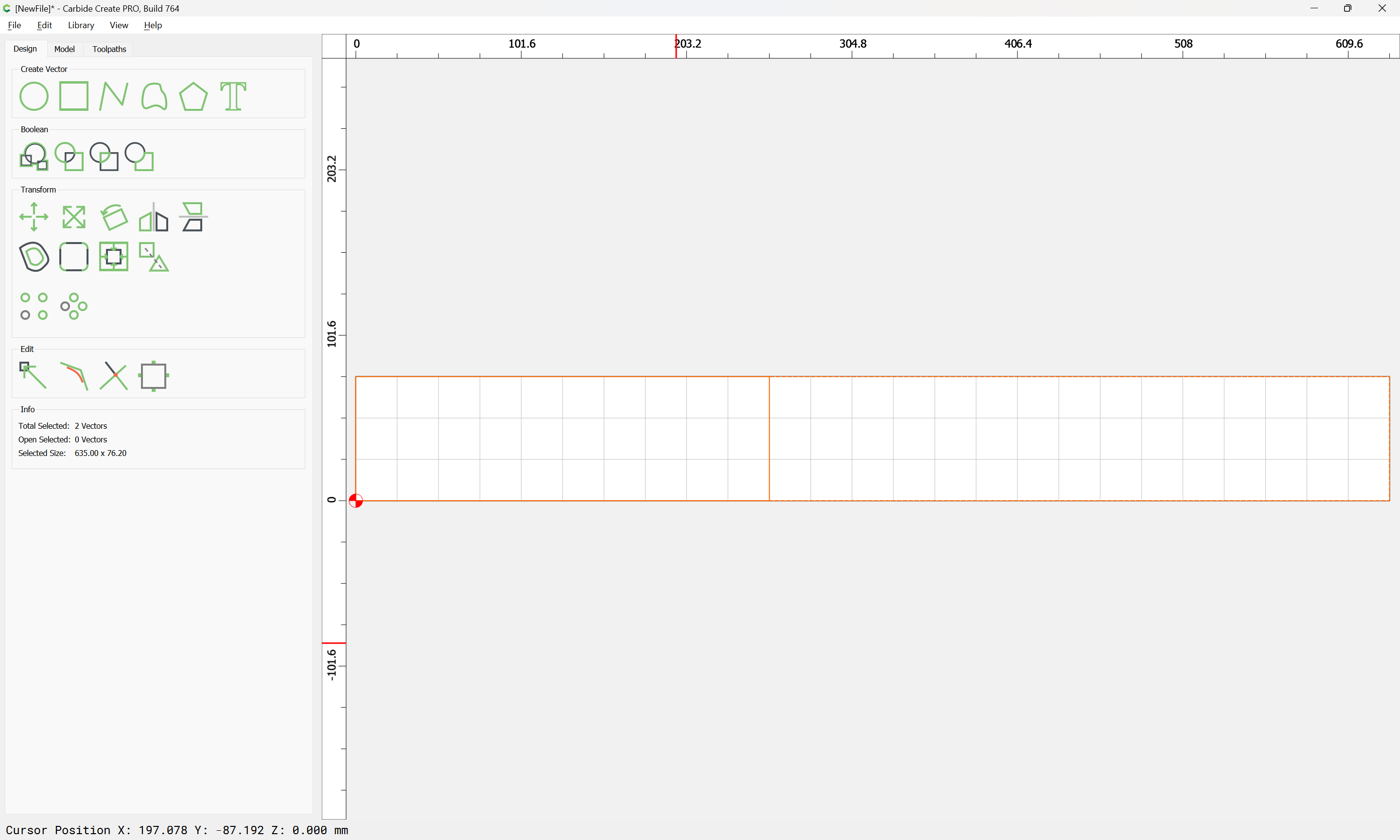
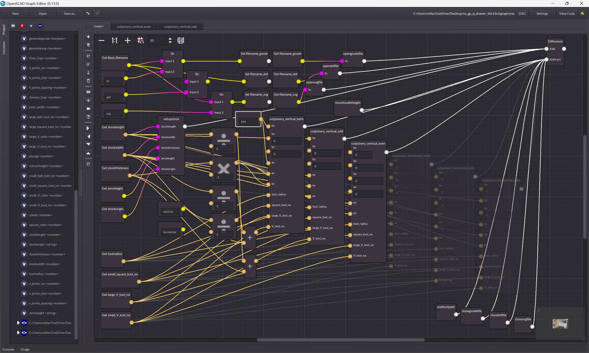
Draw in the overview of each part:

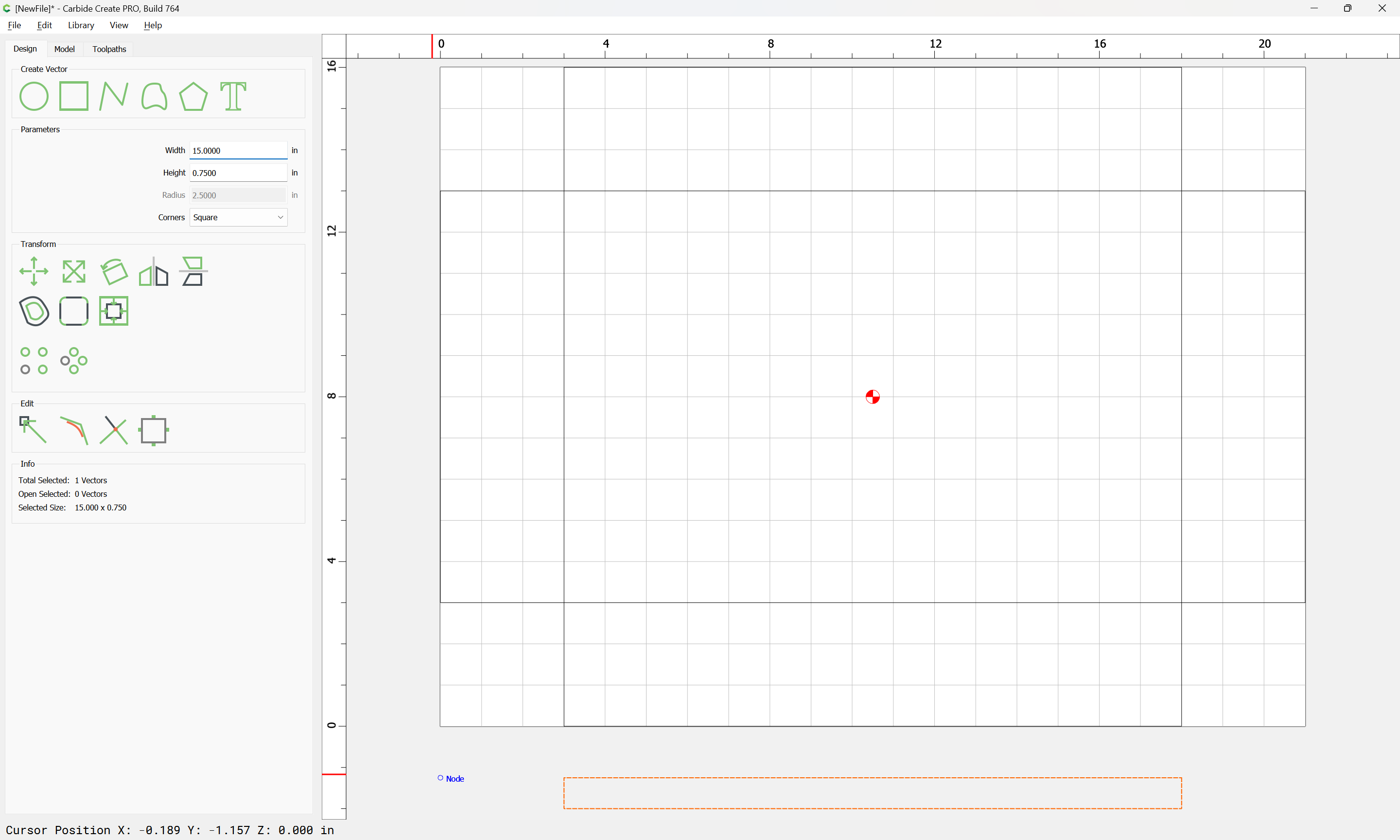
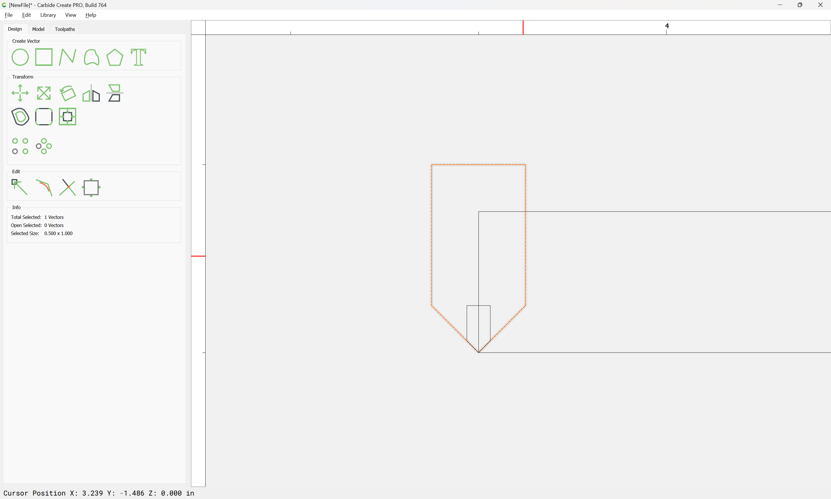
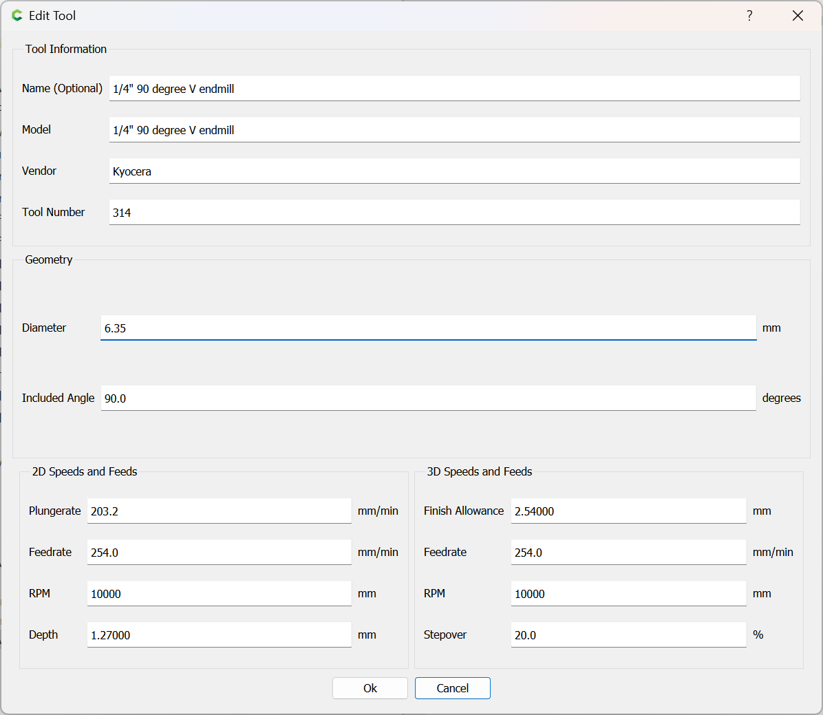
Then, draw the profile of the stock and tools:

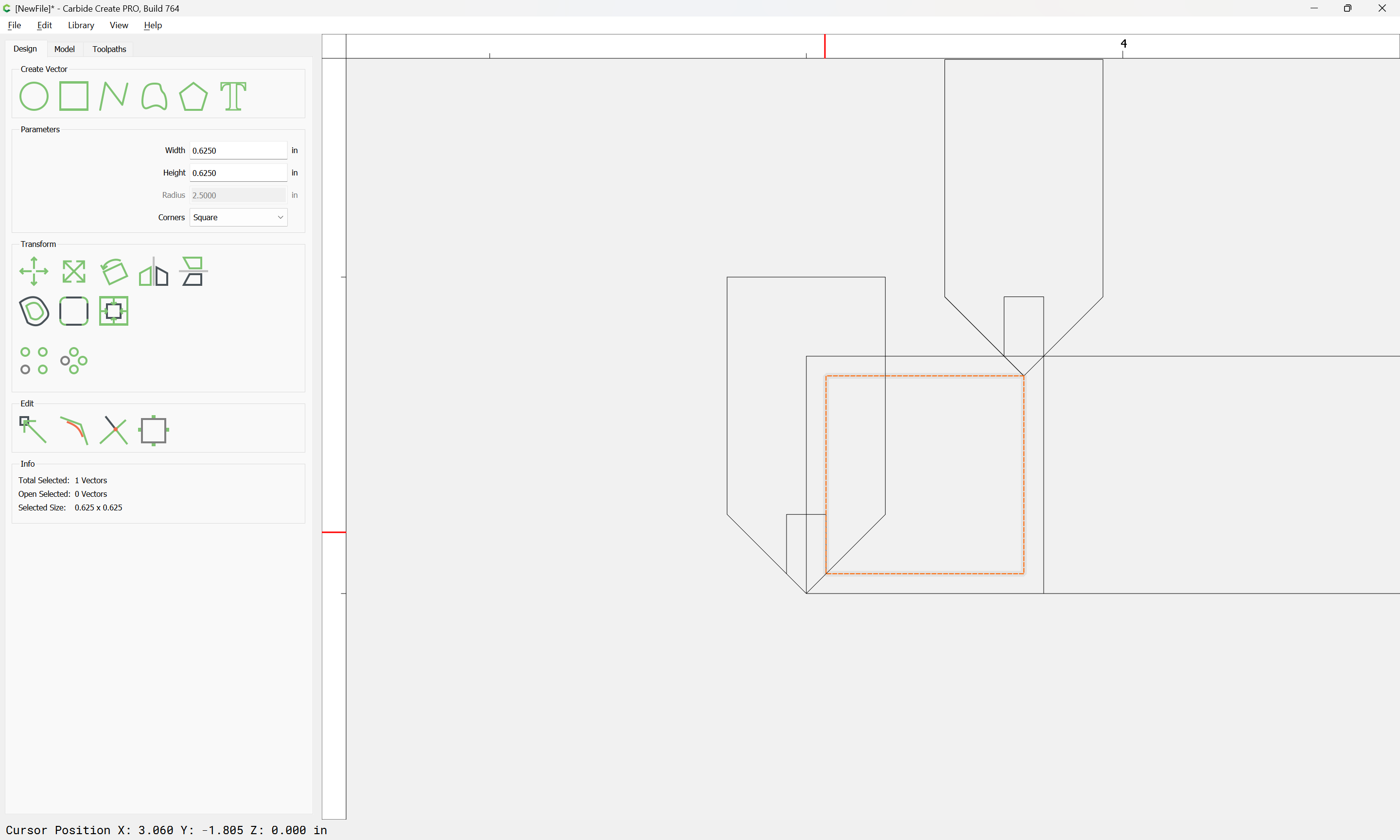
and draw in the profile of the joinery:

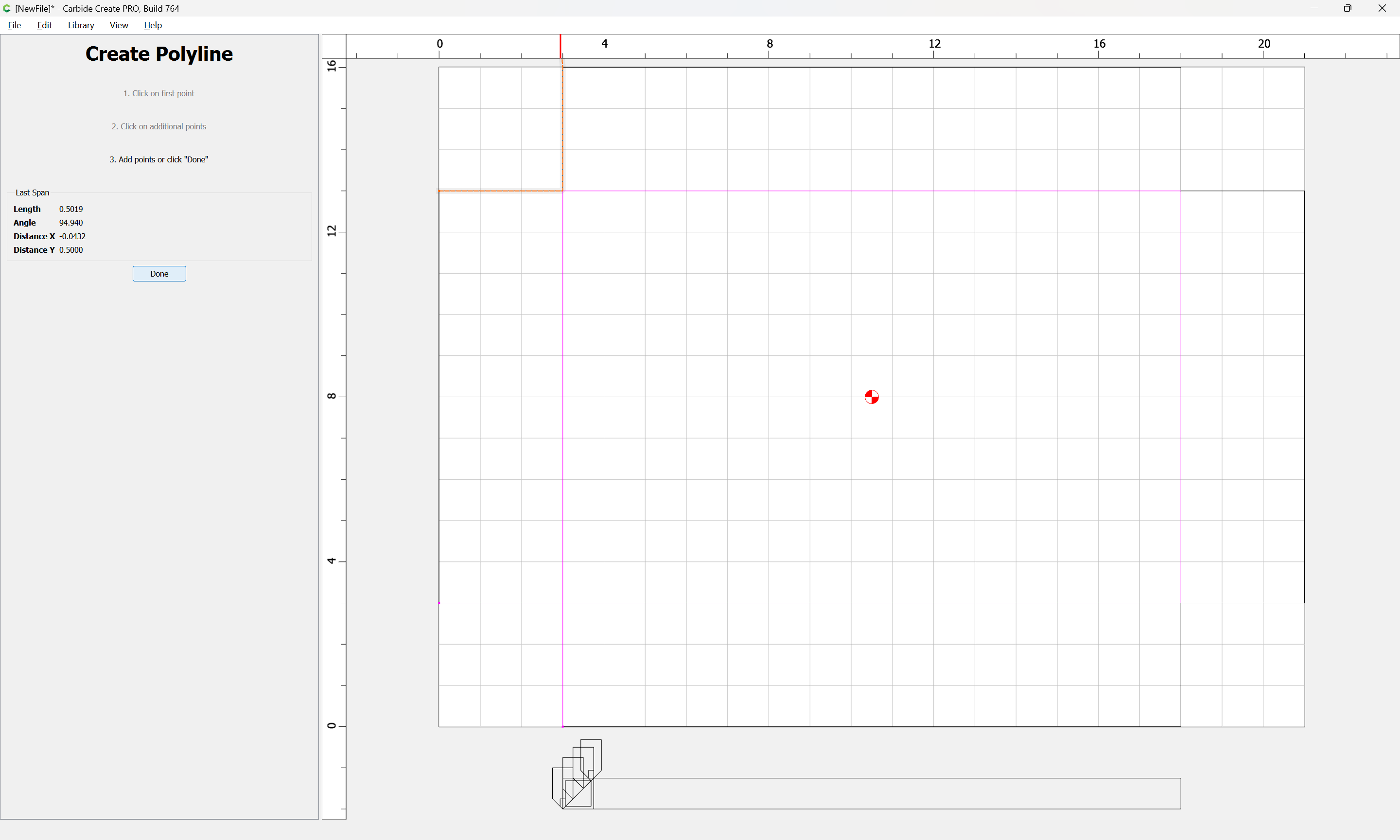
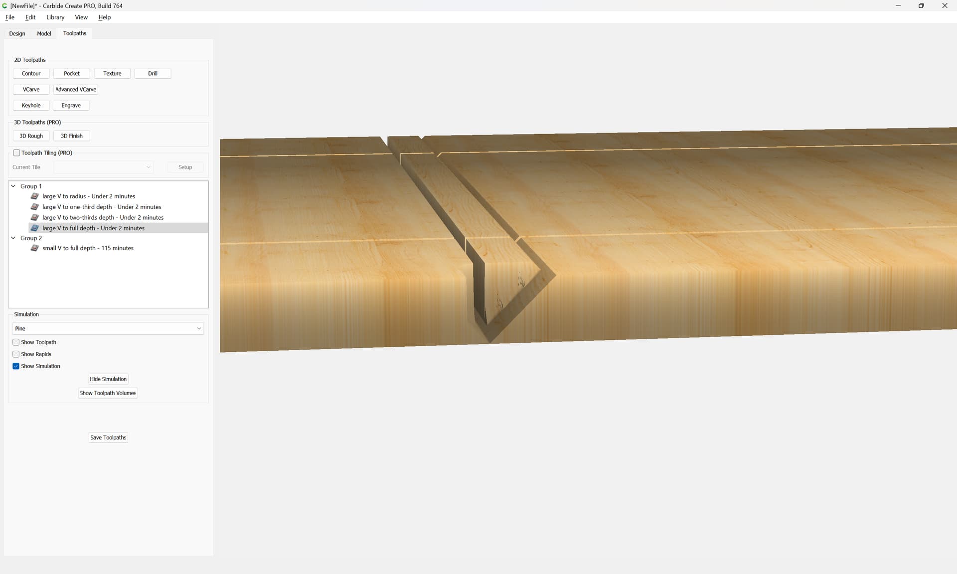
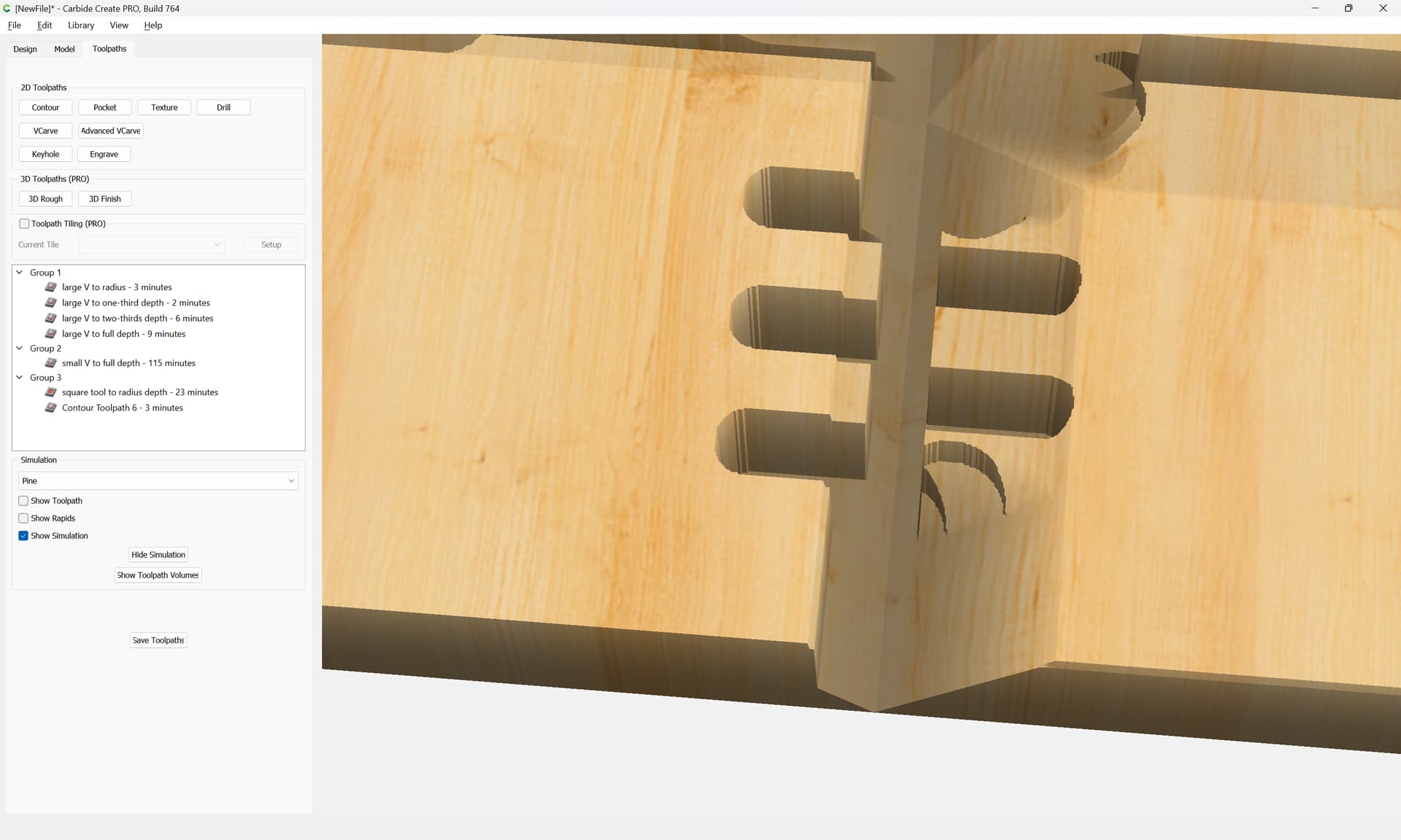
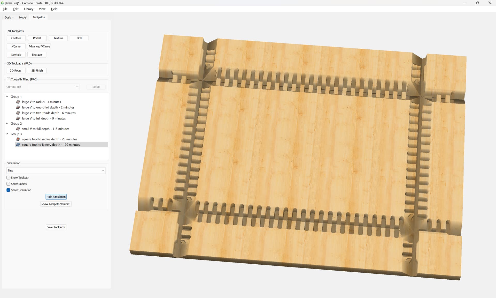
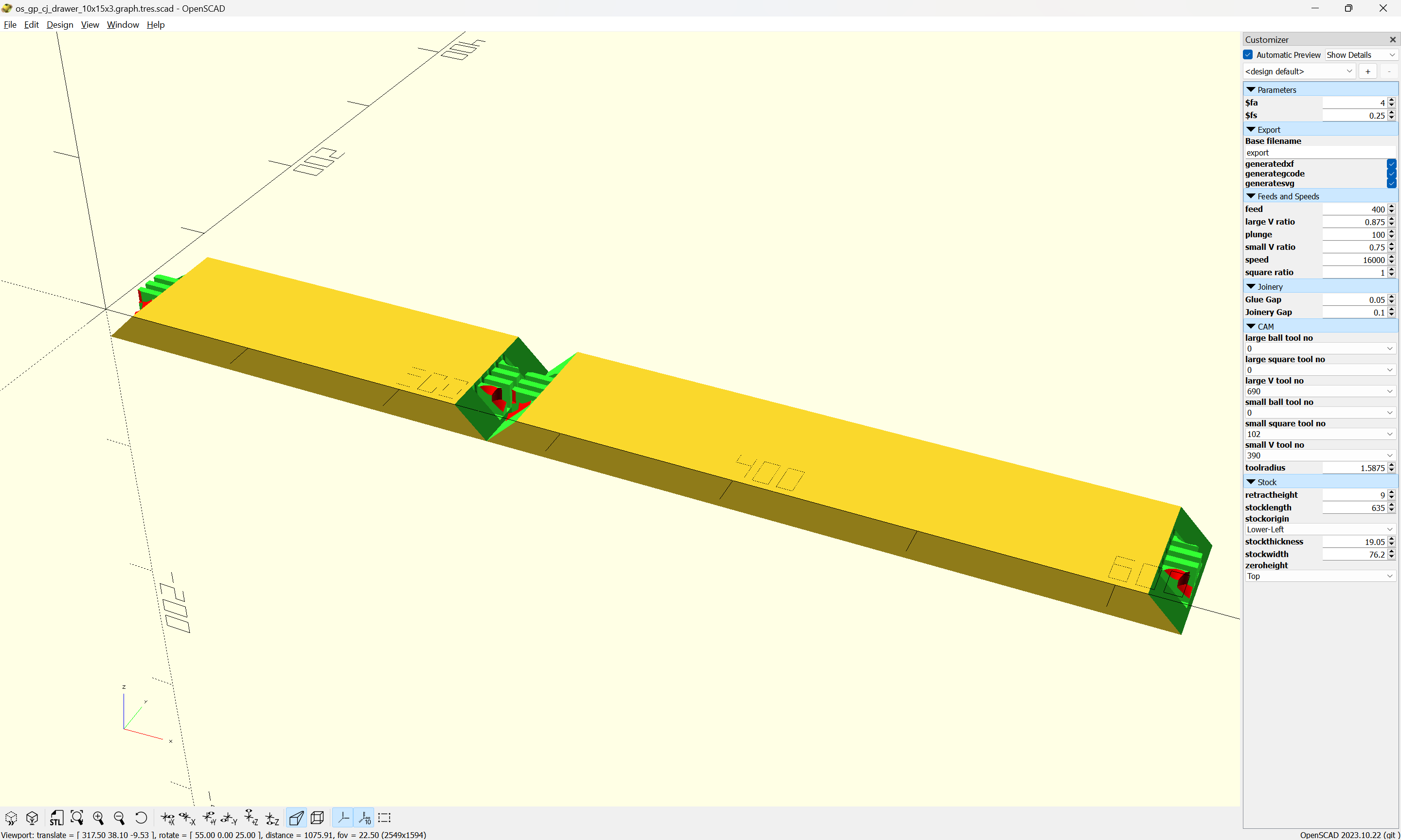
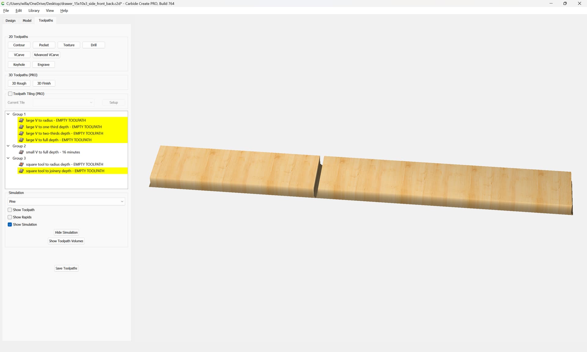
Note that due to the thickness of the stock, multiple passes with the V tool will be necessary:

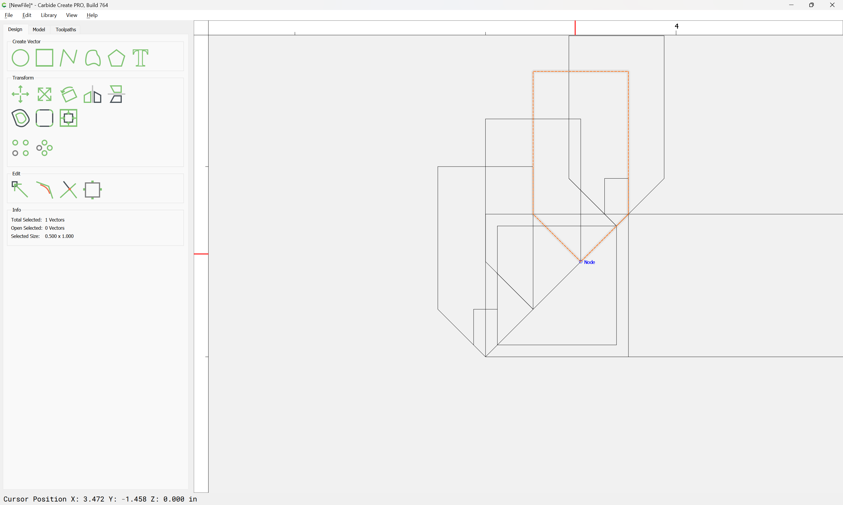
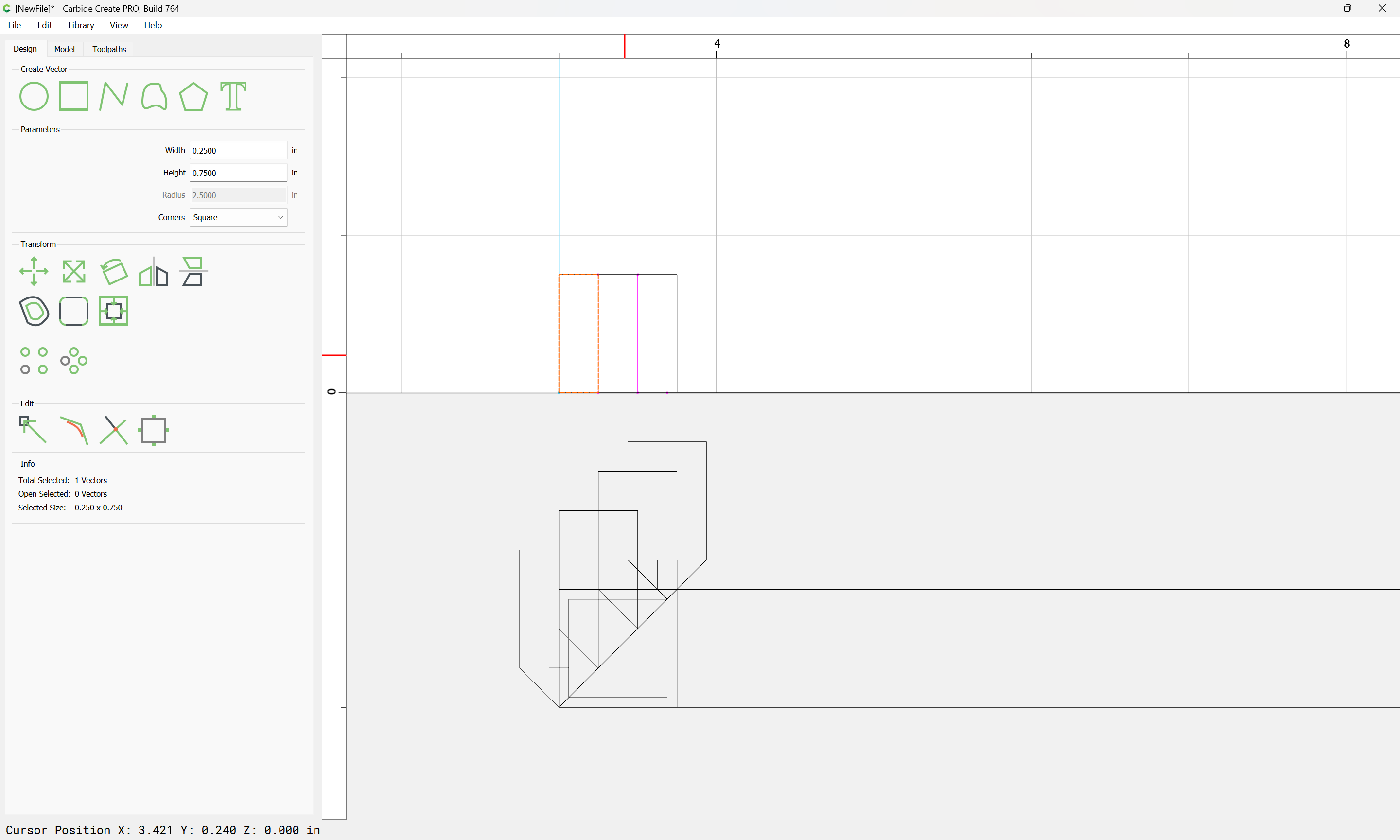
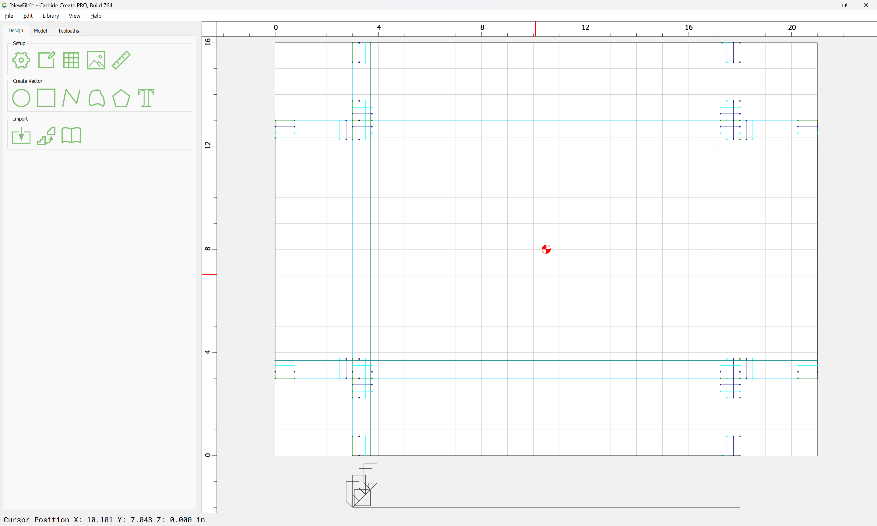
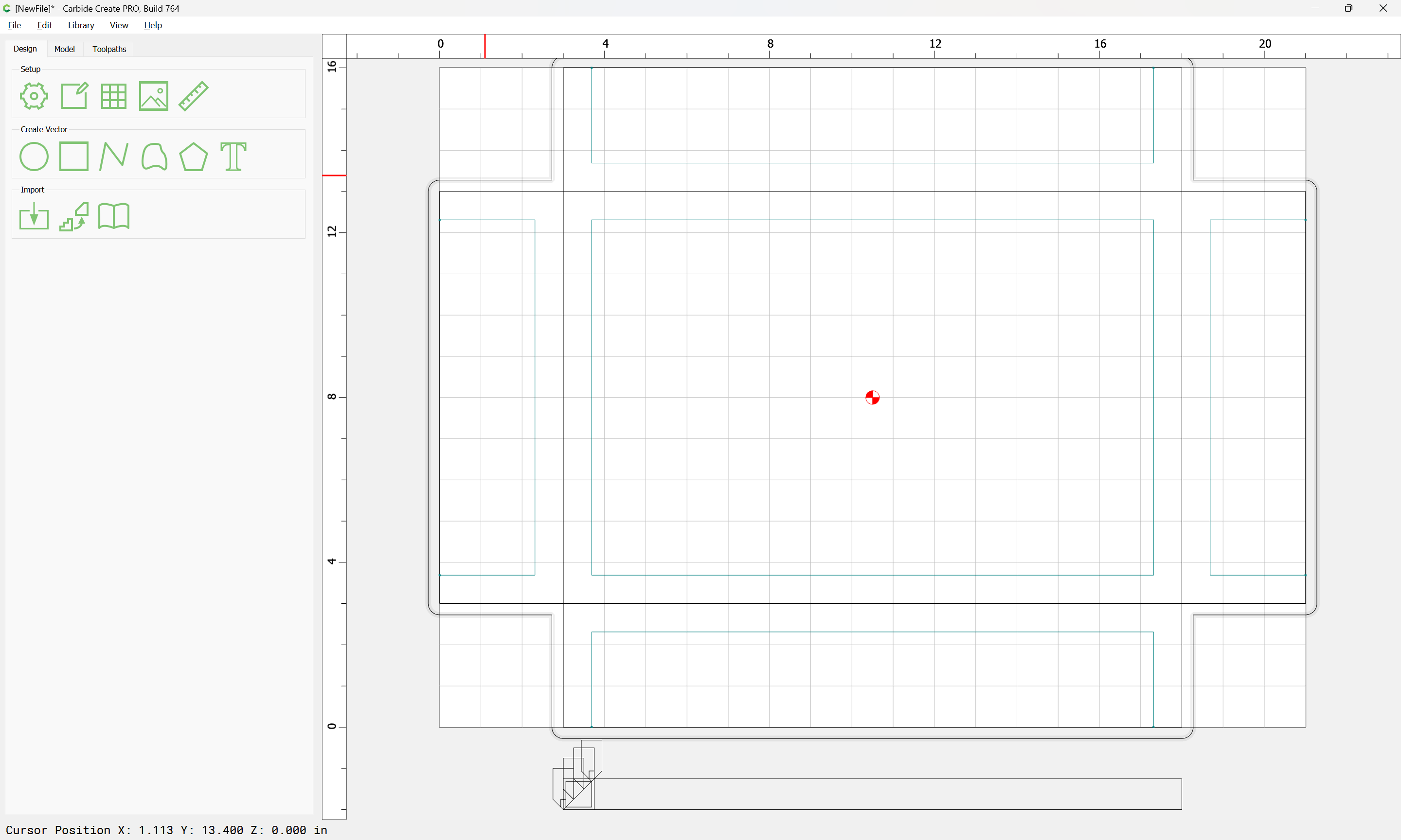
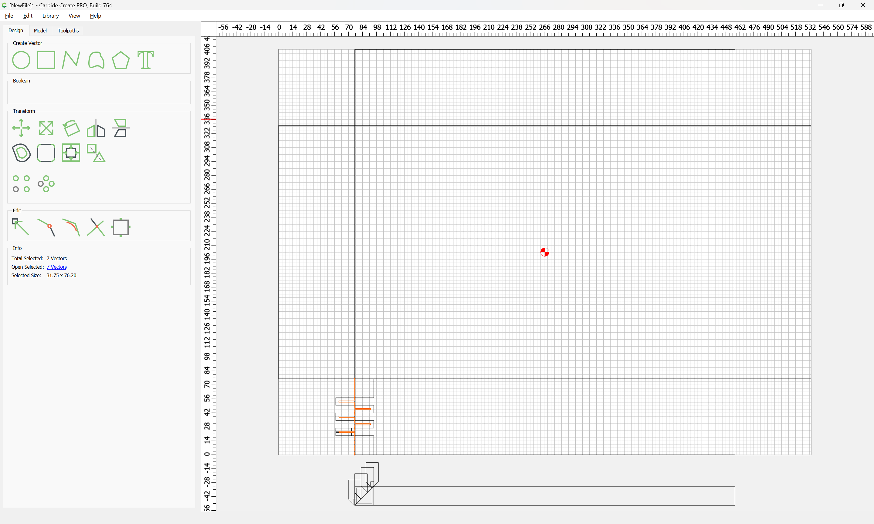
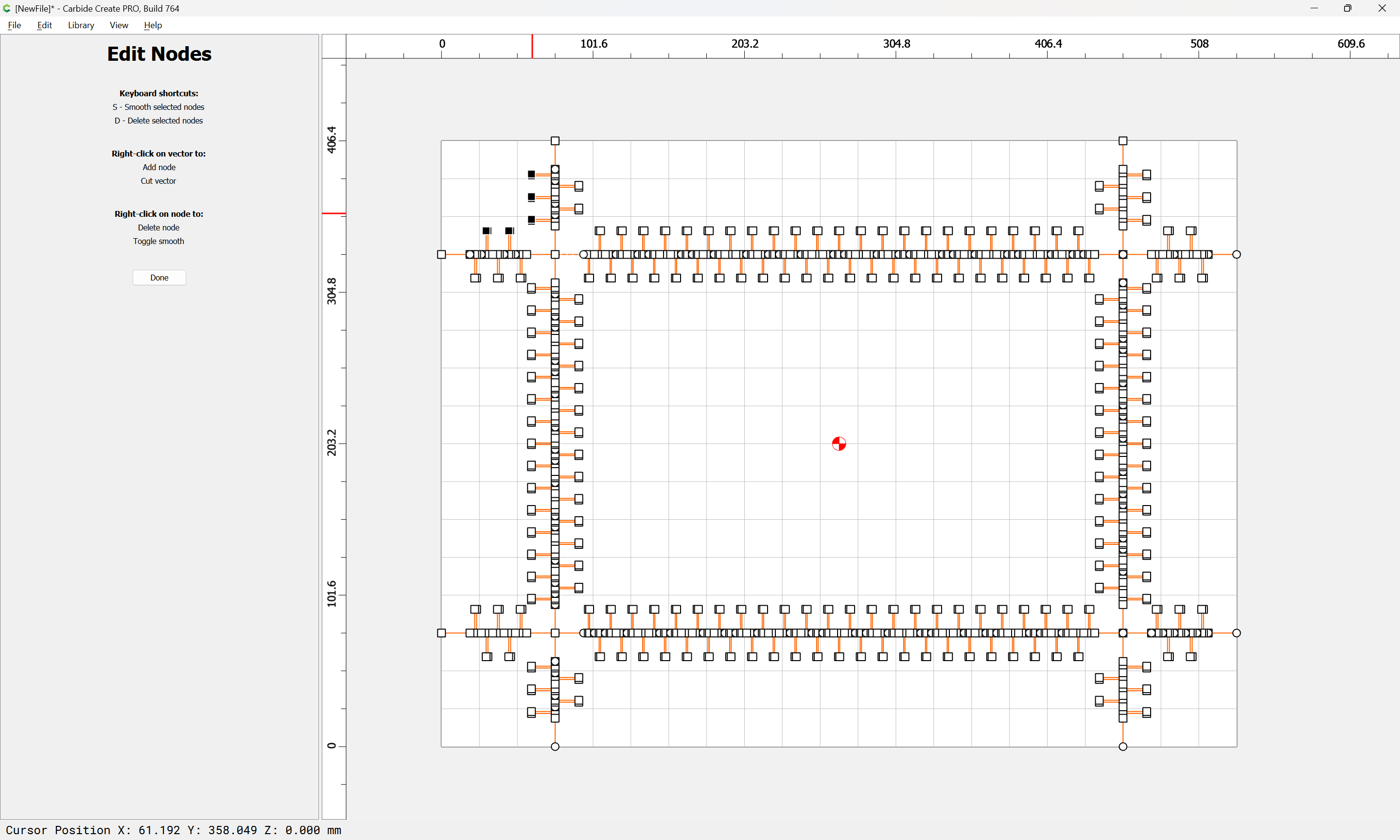
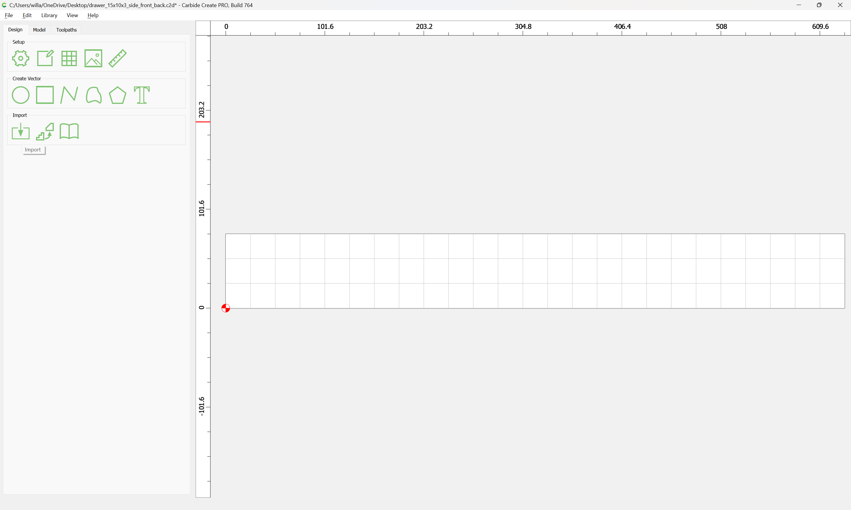
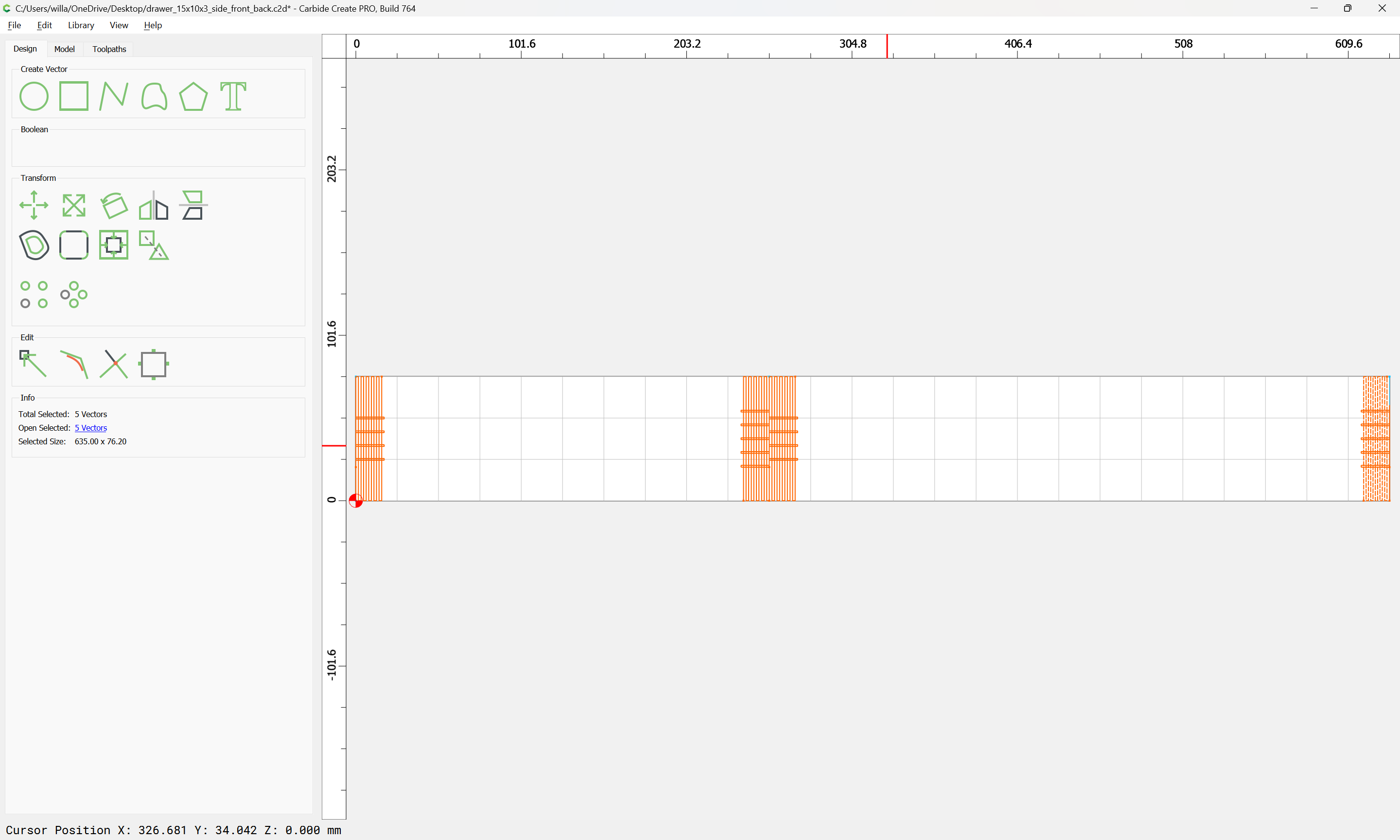
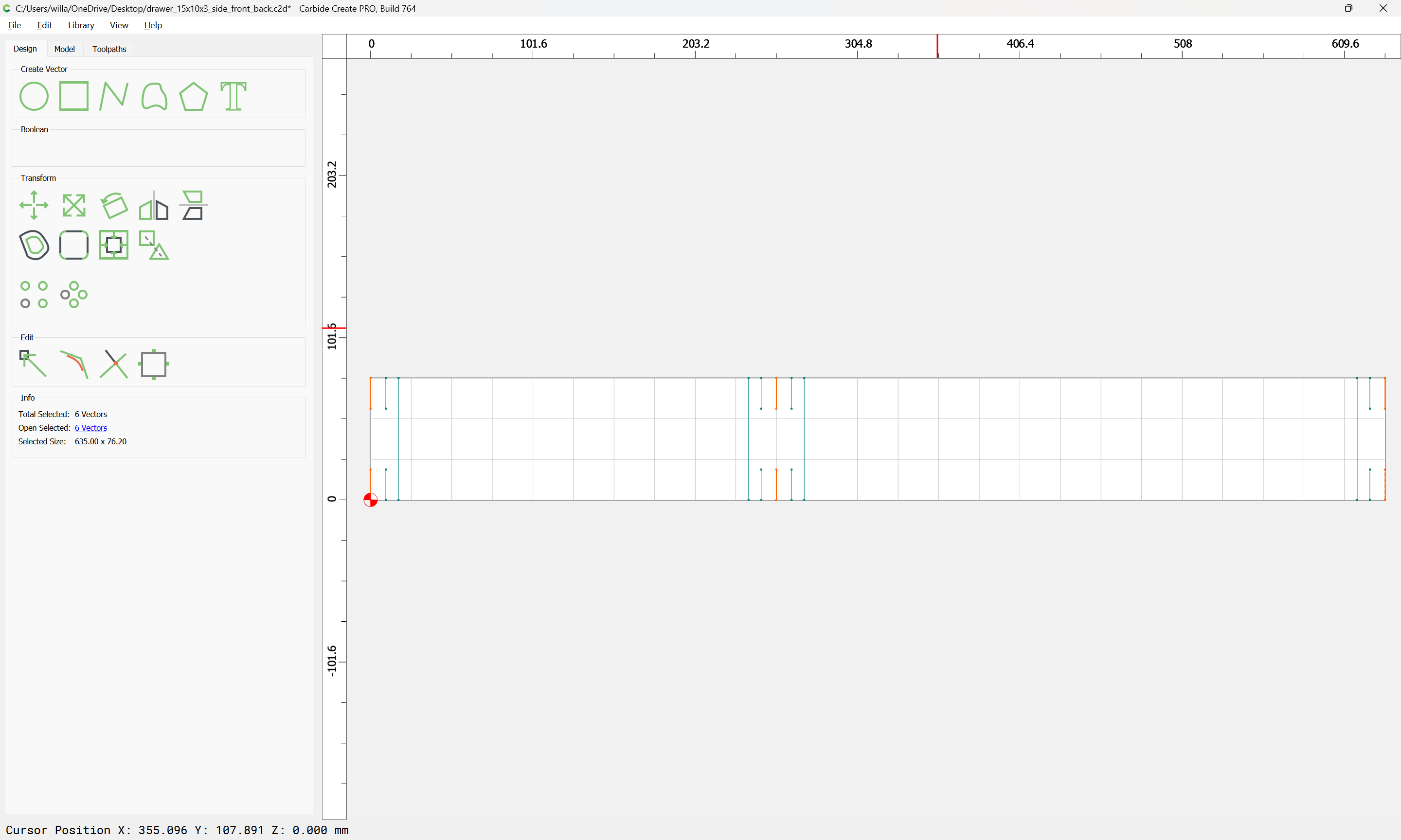
It’s easier to draw things in from the bottom:

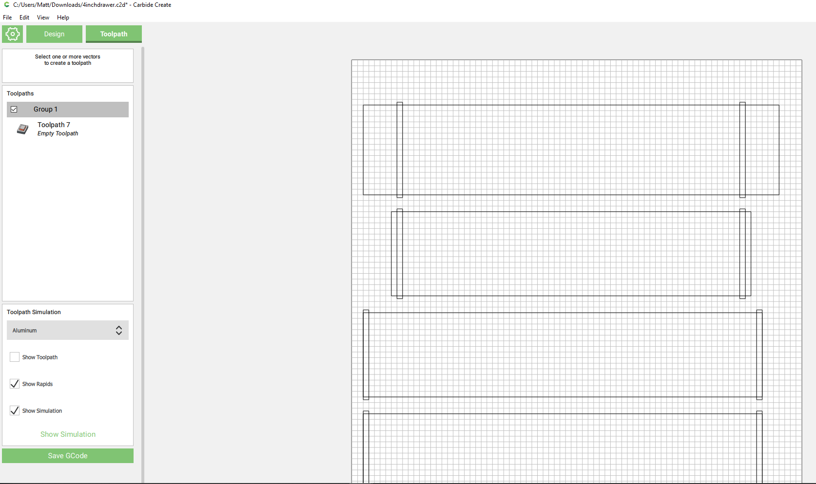
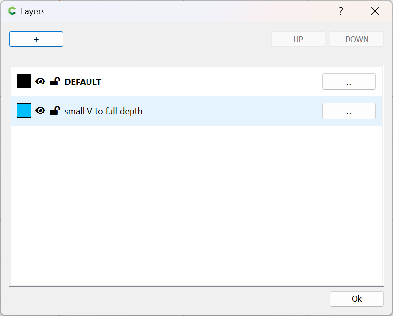
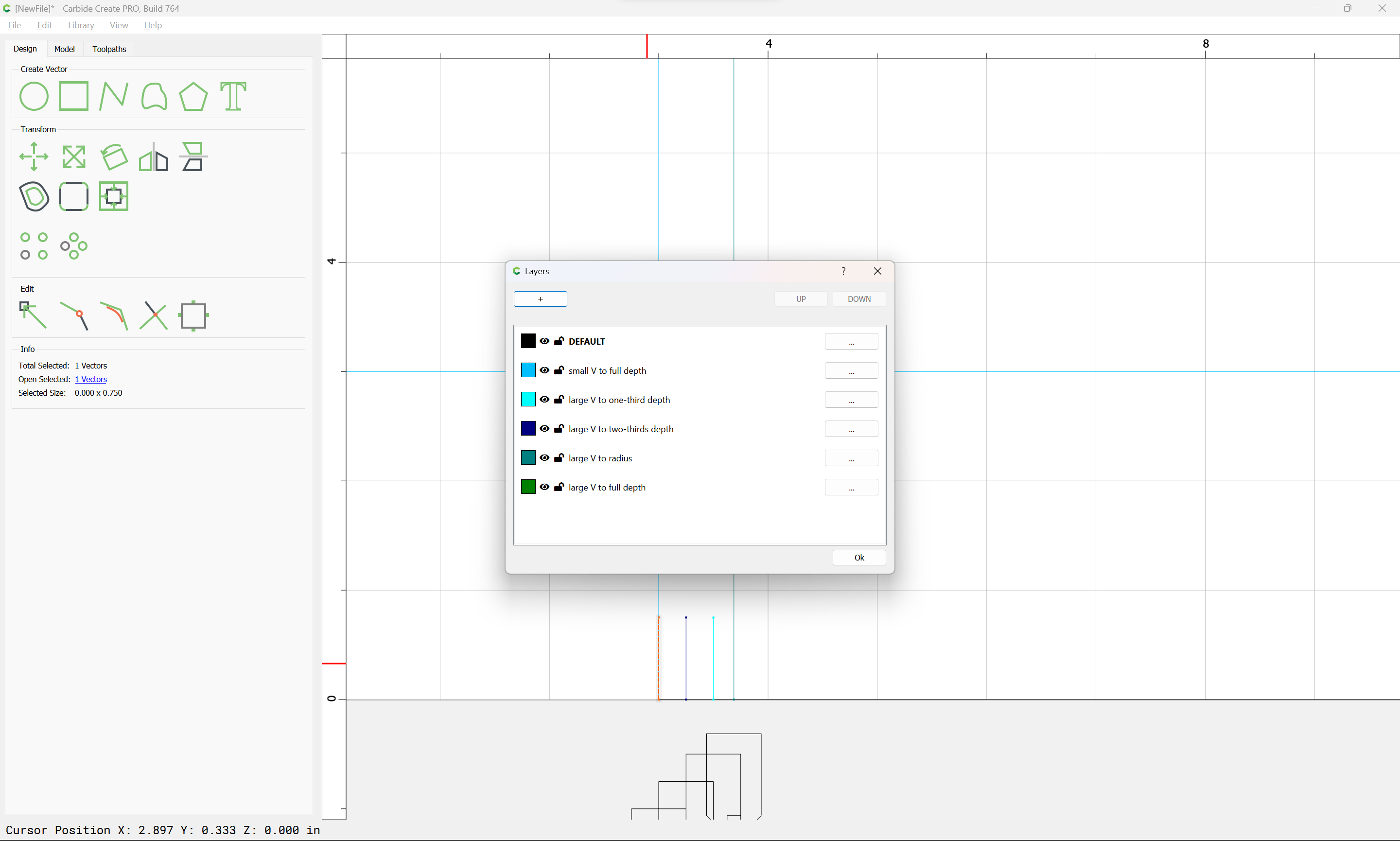
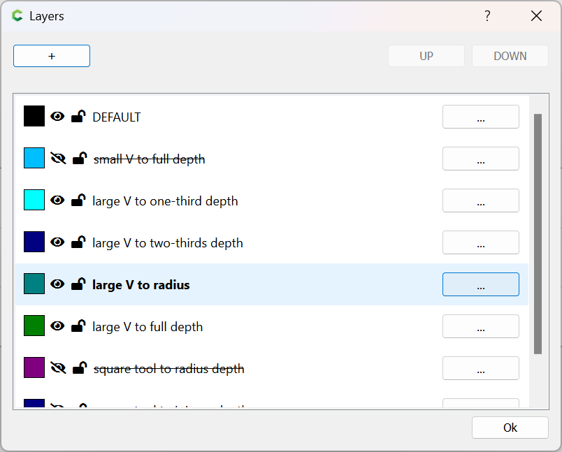
It will be easiest to isolate the geometry for each toolpath on its own layer:

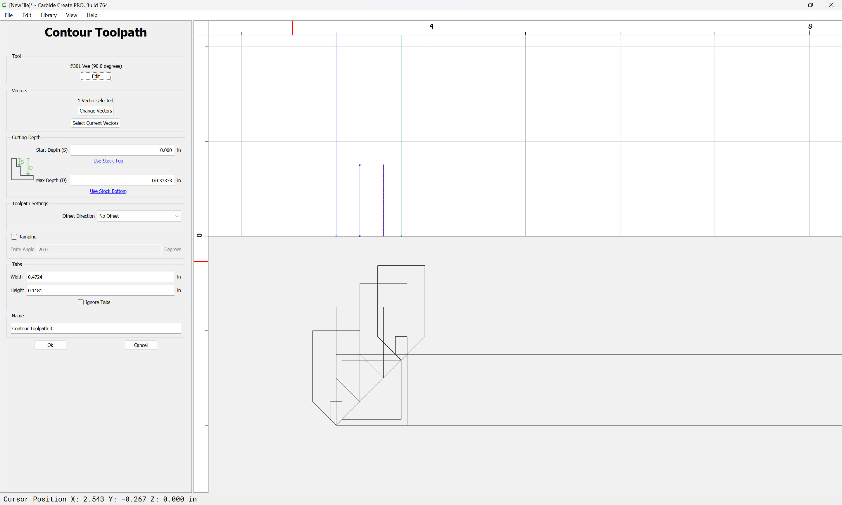
Make a new Contour toolpath and:
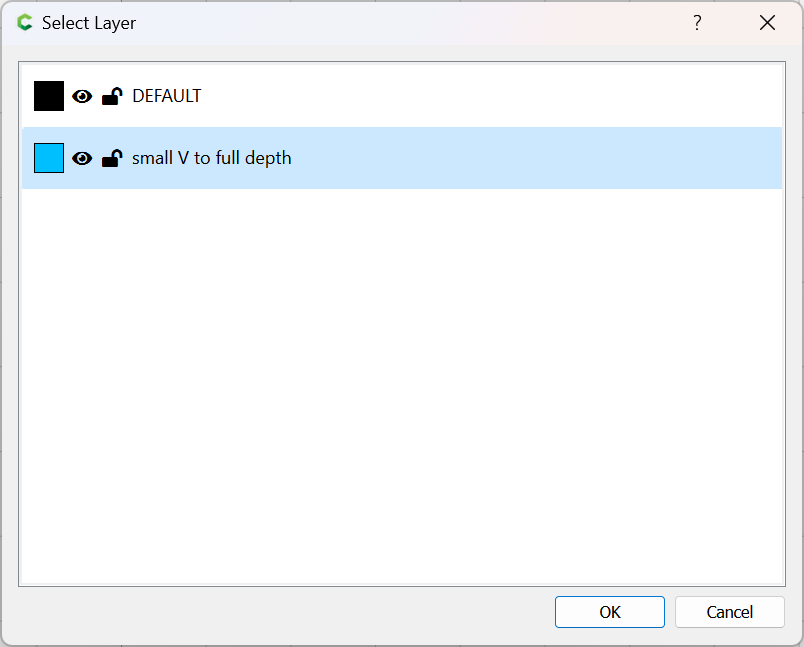
image

Select by Layer:

OK

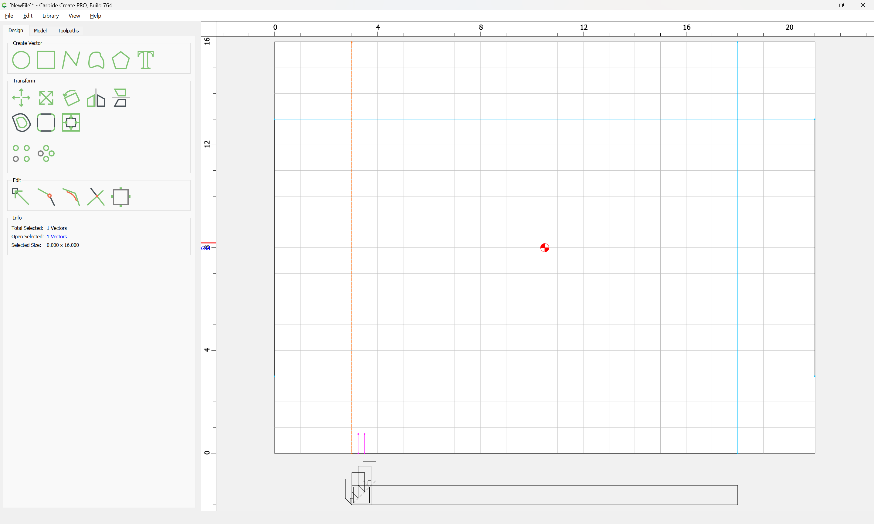
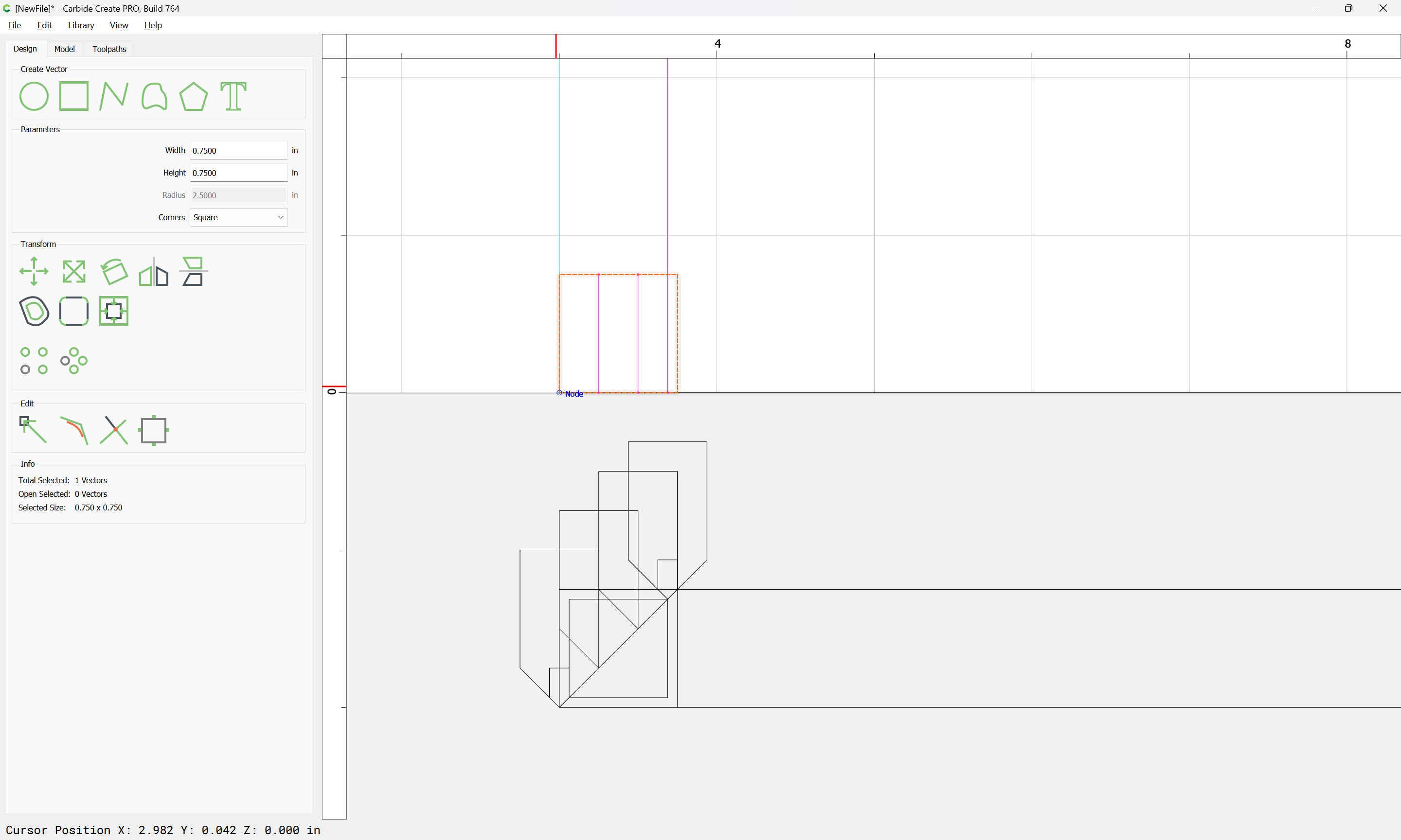
For each V cut along the ends of the joints you will want an 0.75" or so contour:

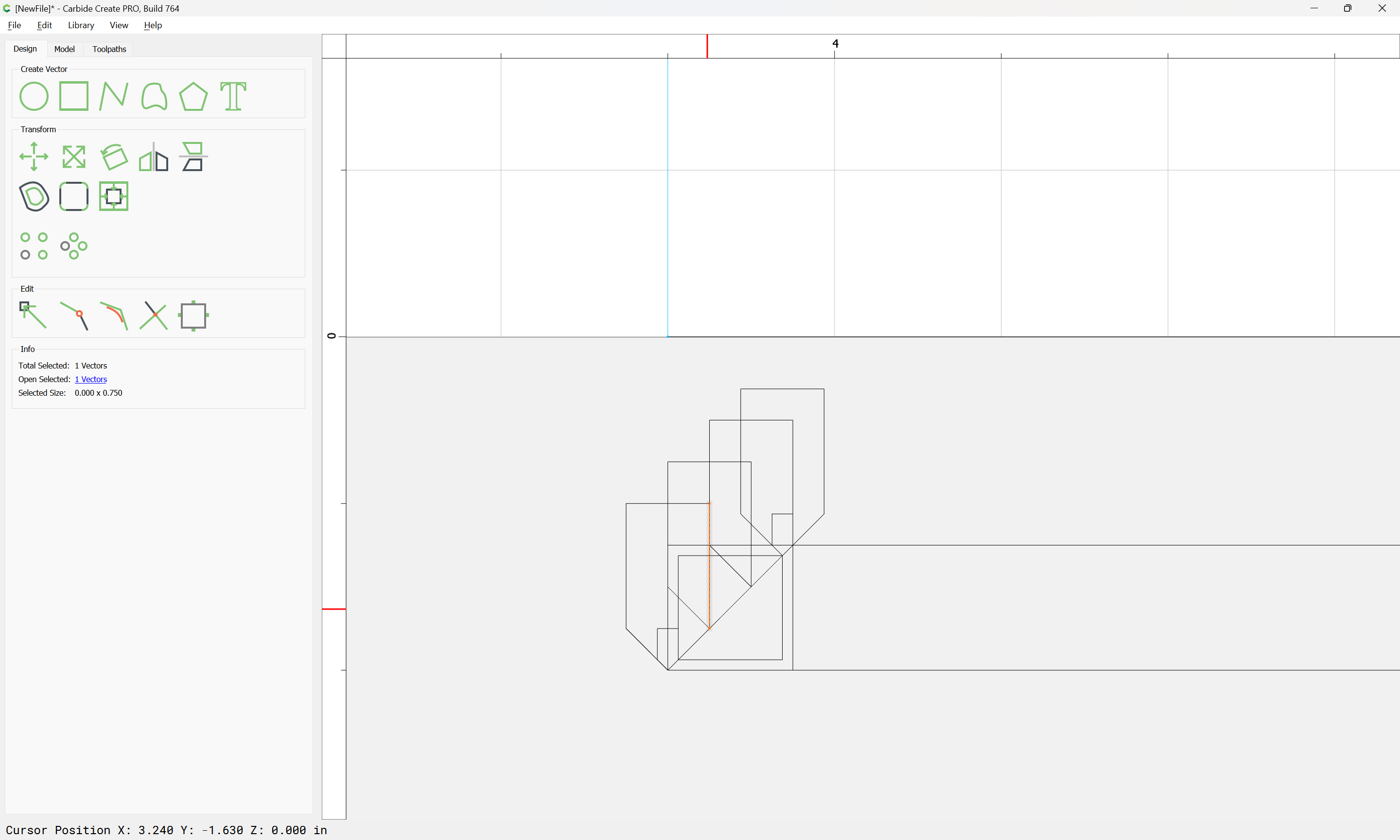
arranged at the proper distance from from the bottom of the joint:

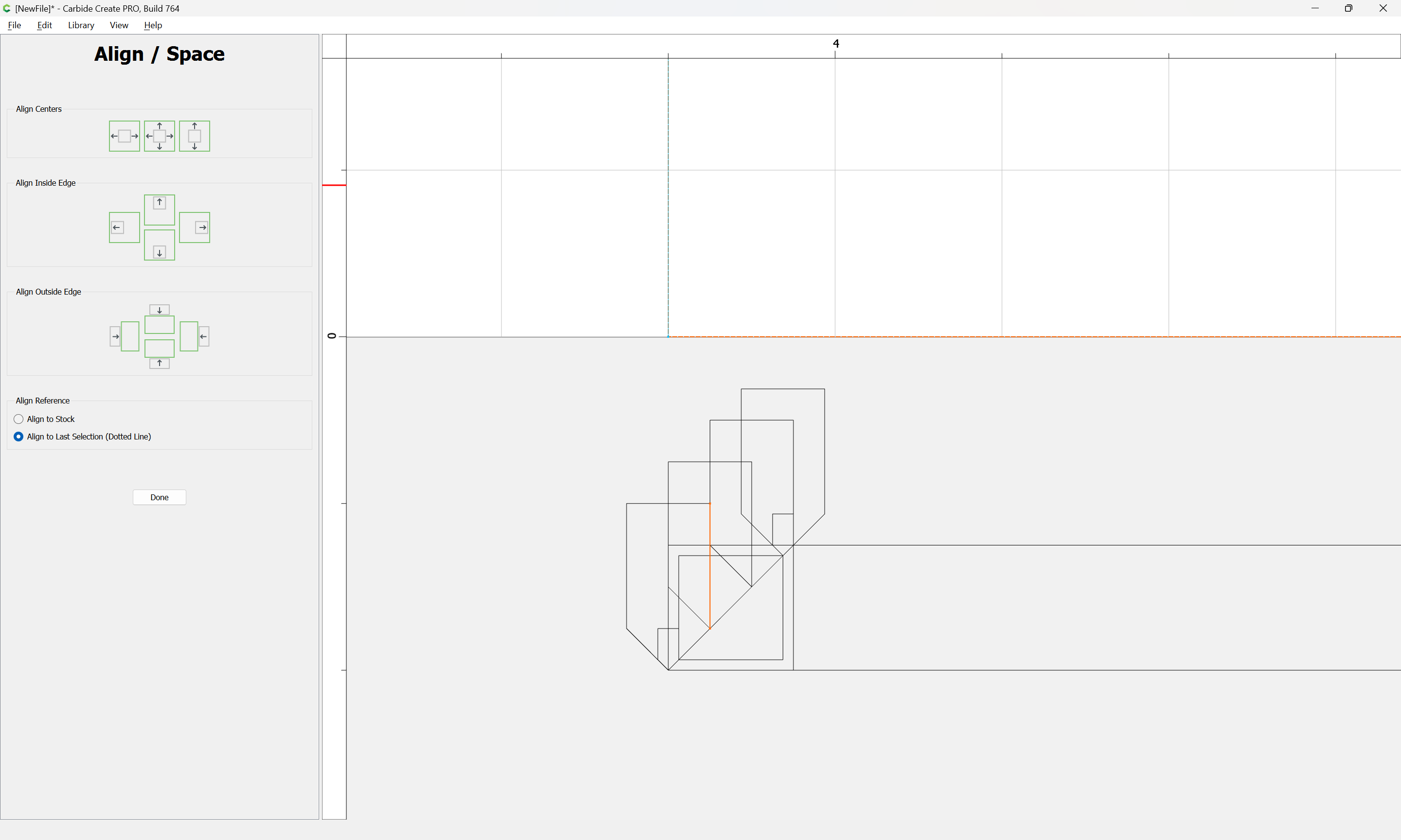
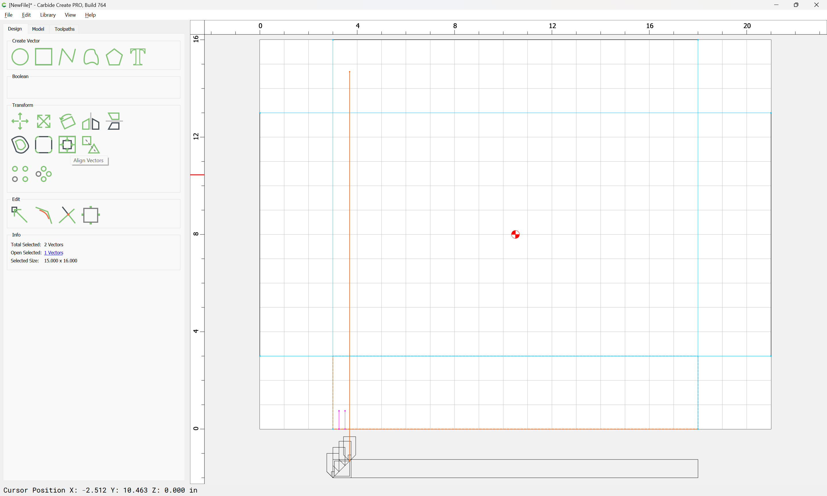
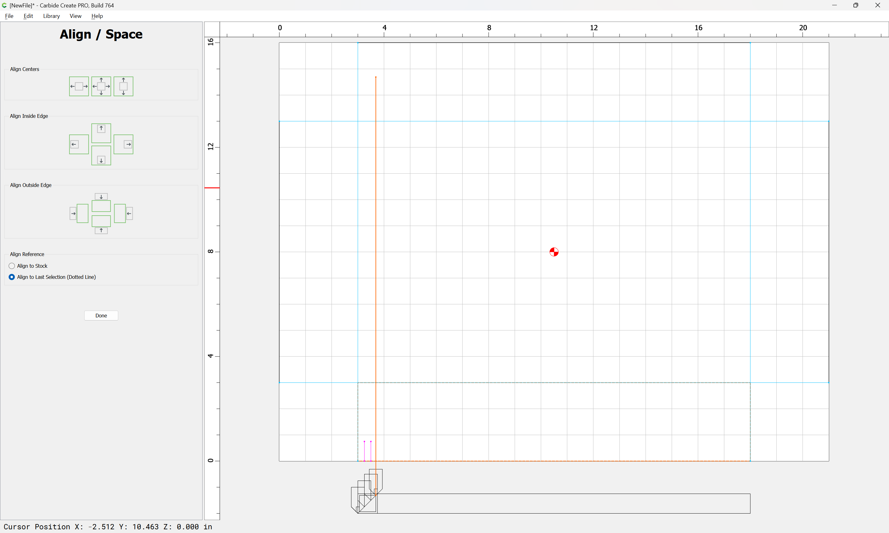
and aligned at the right place:

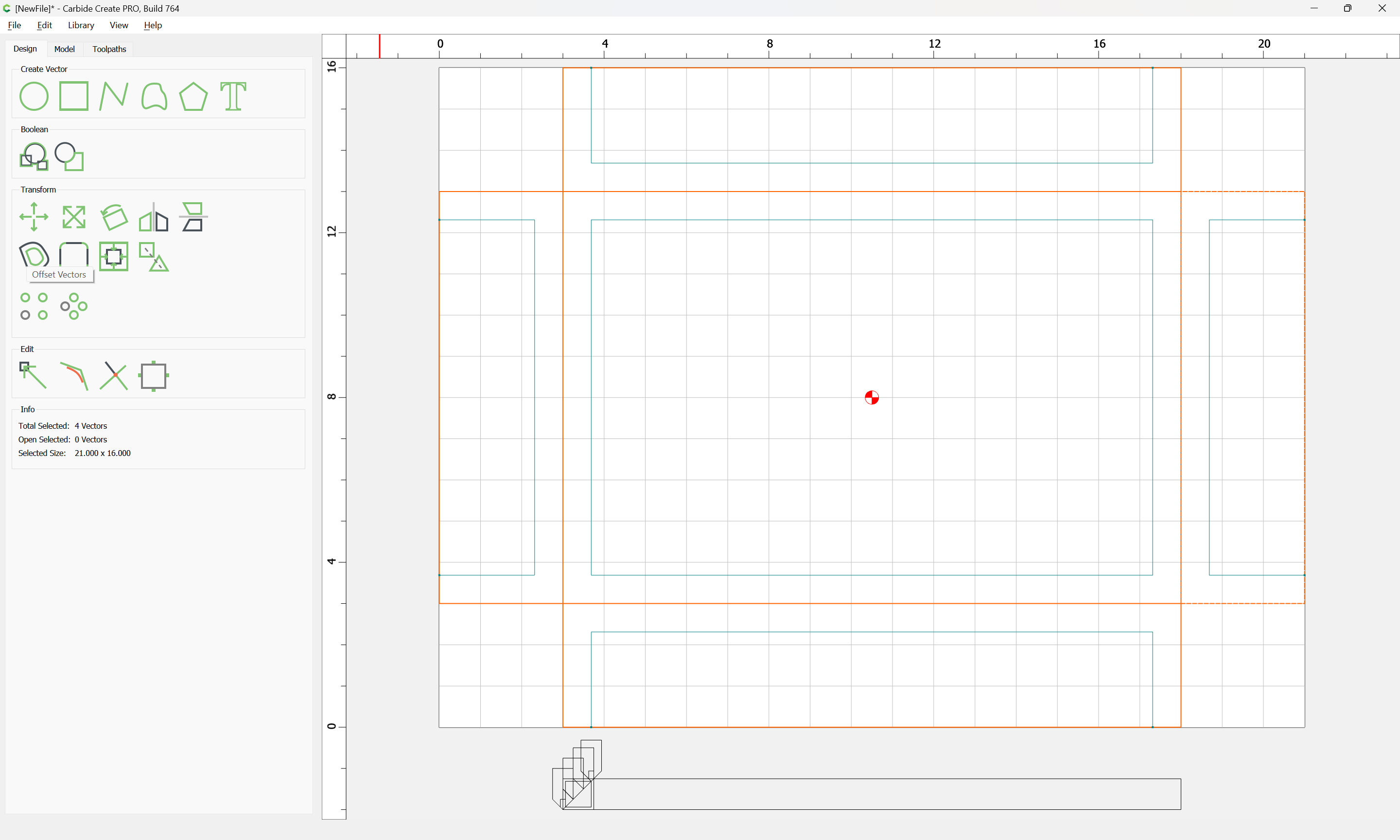
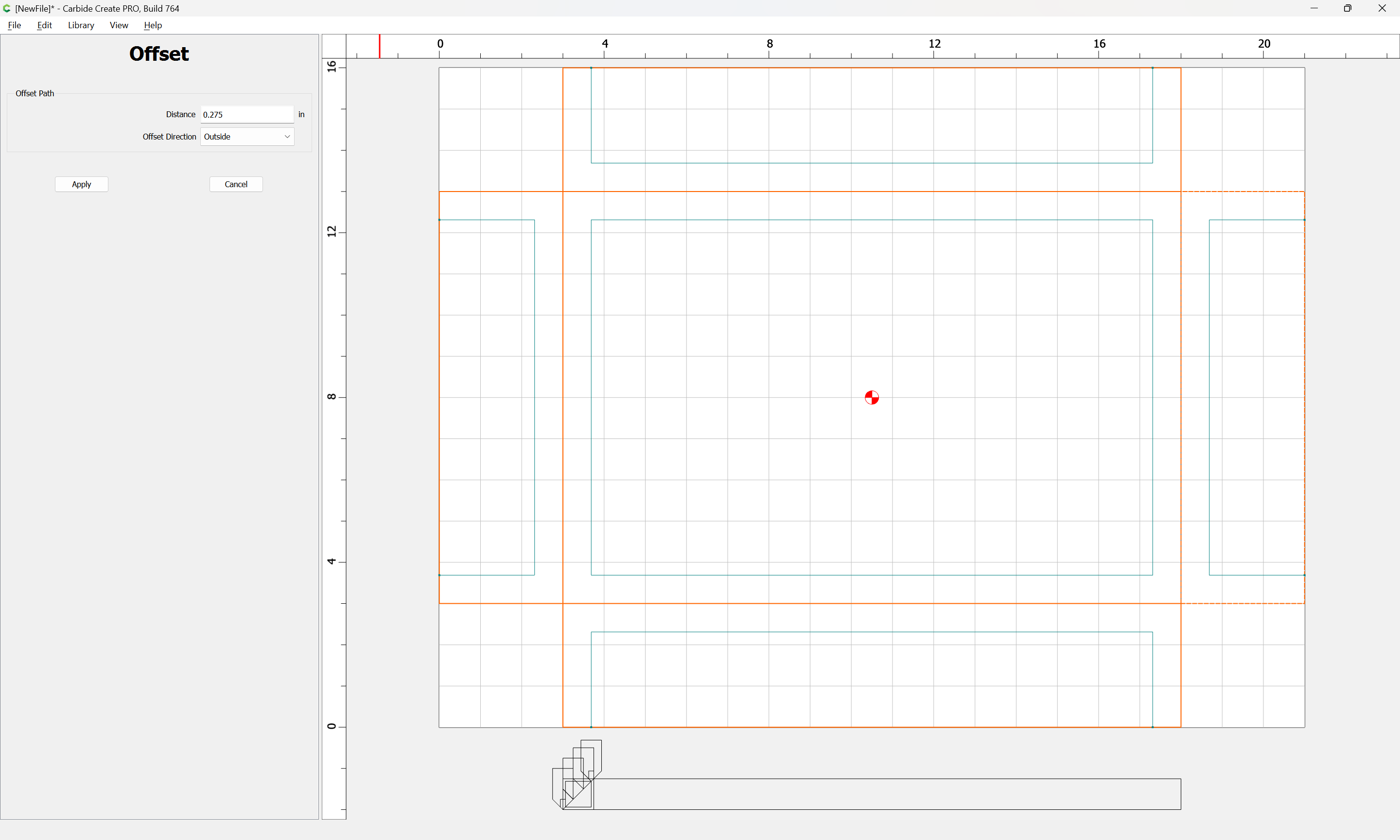
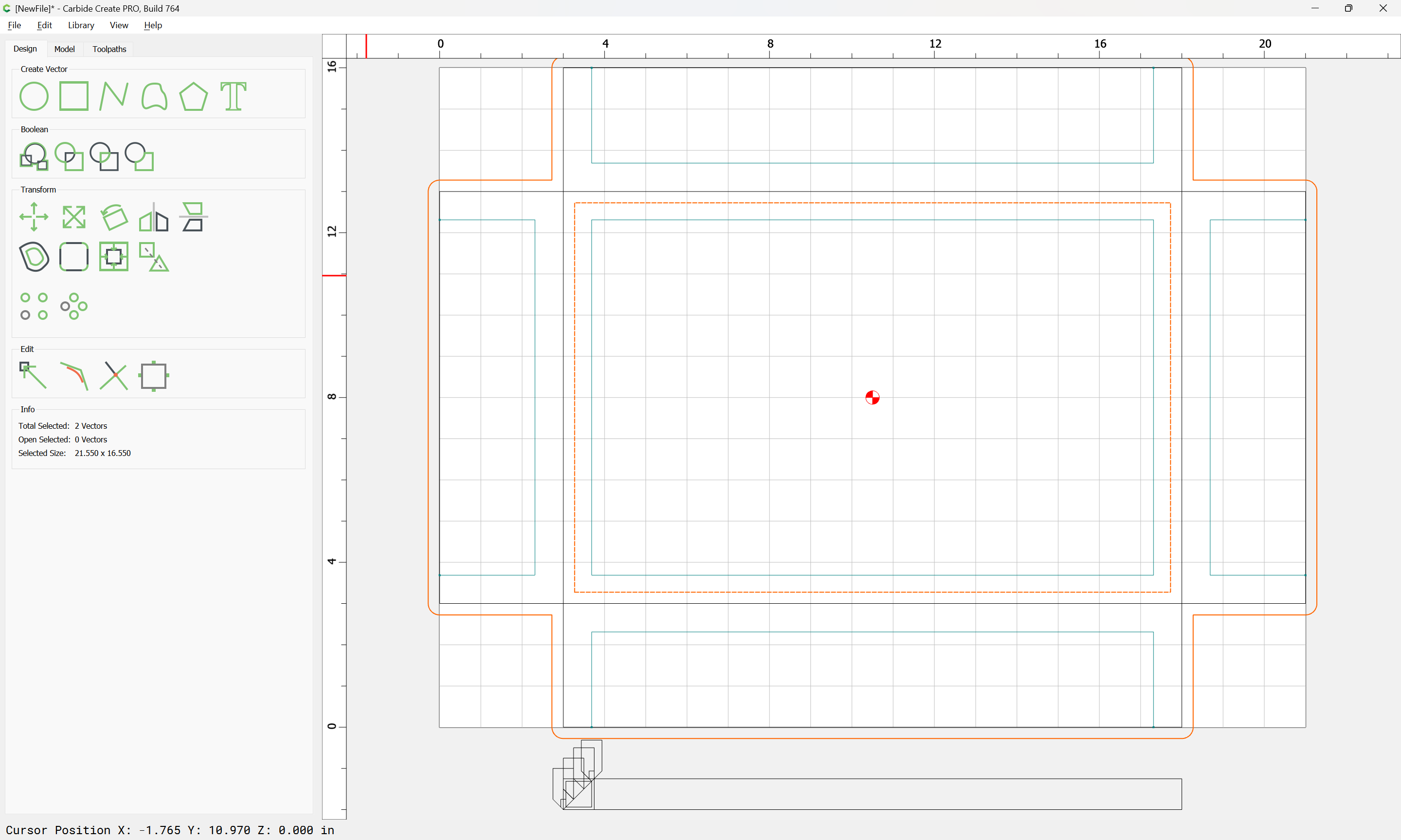
and a cut inset from the perimeter:

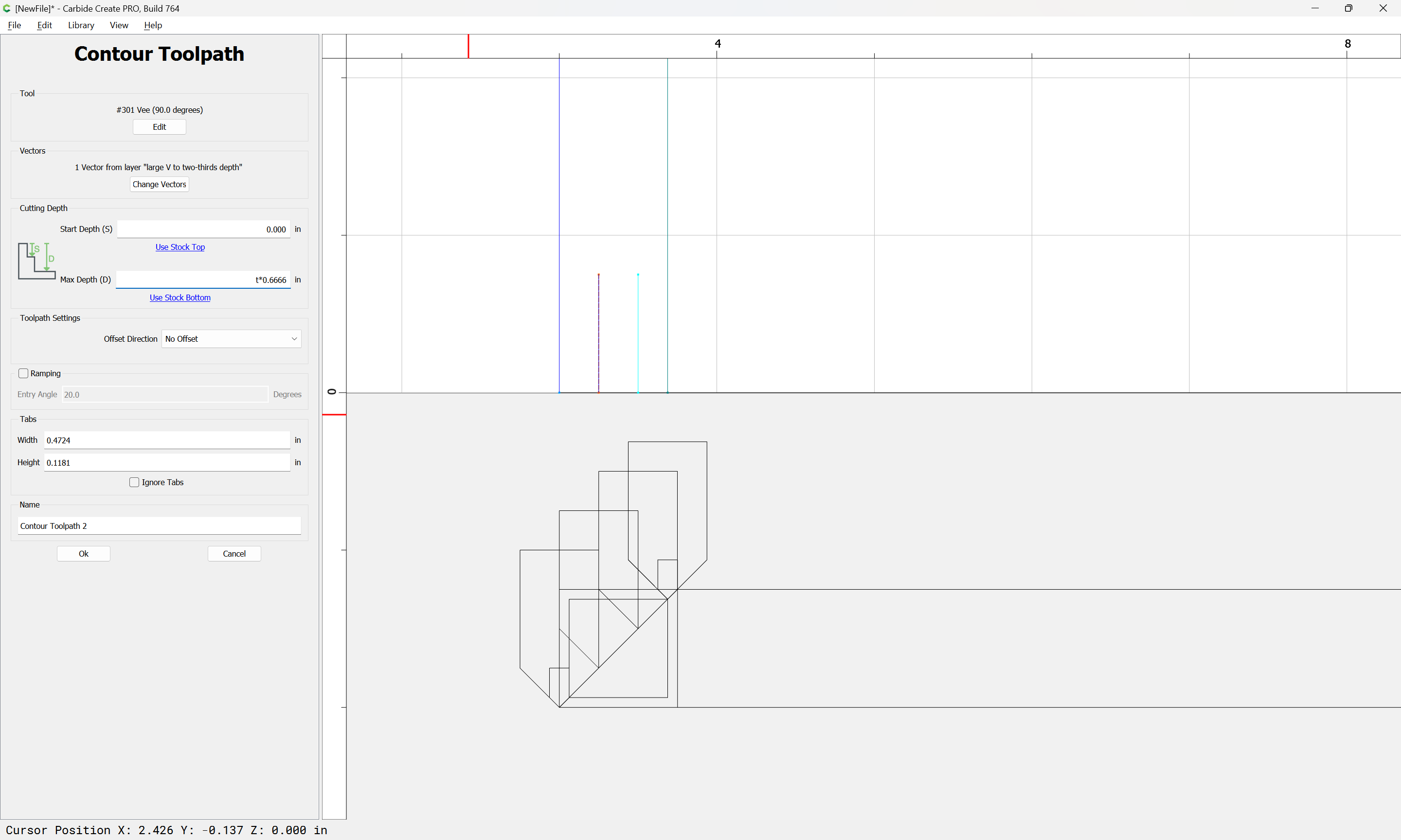
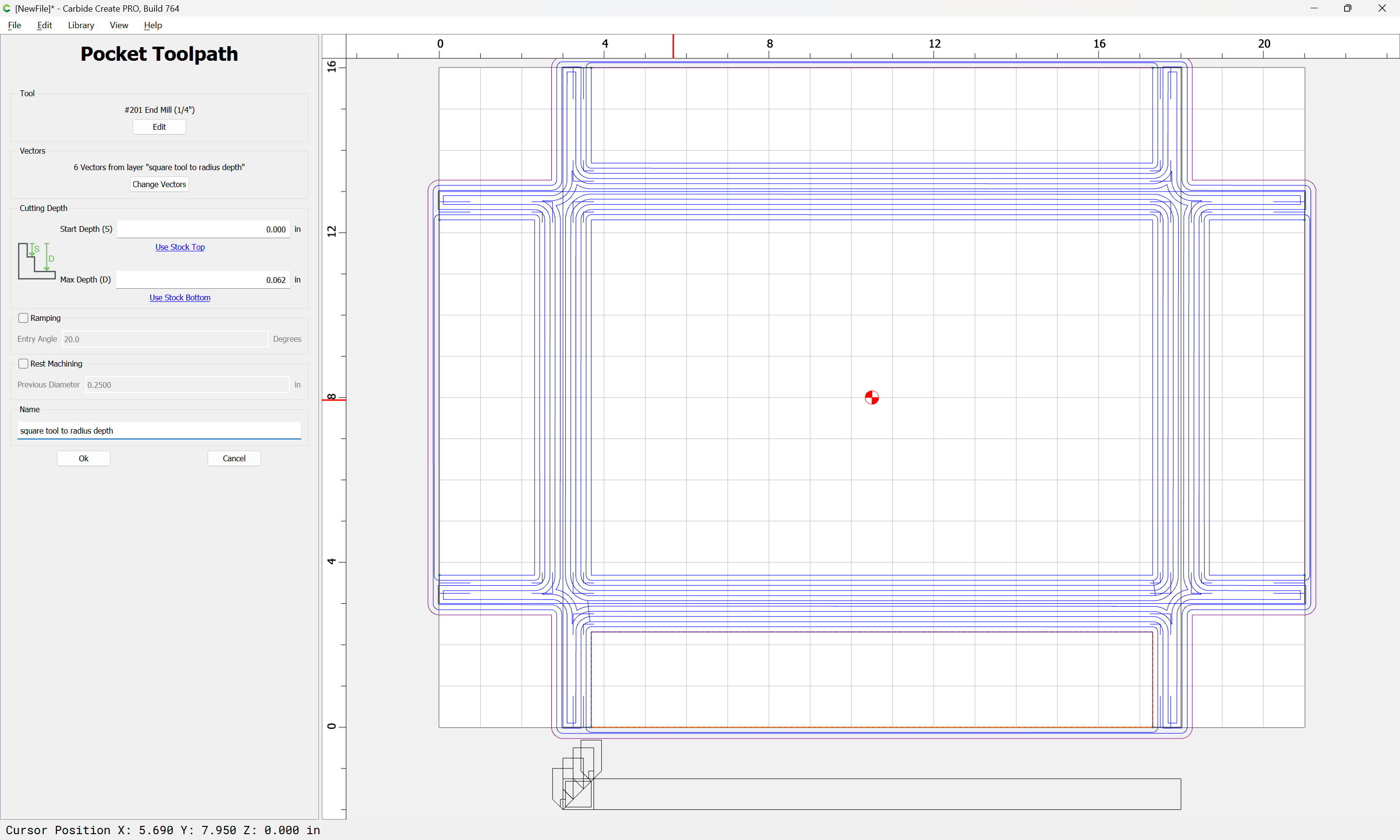
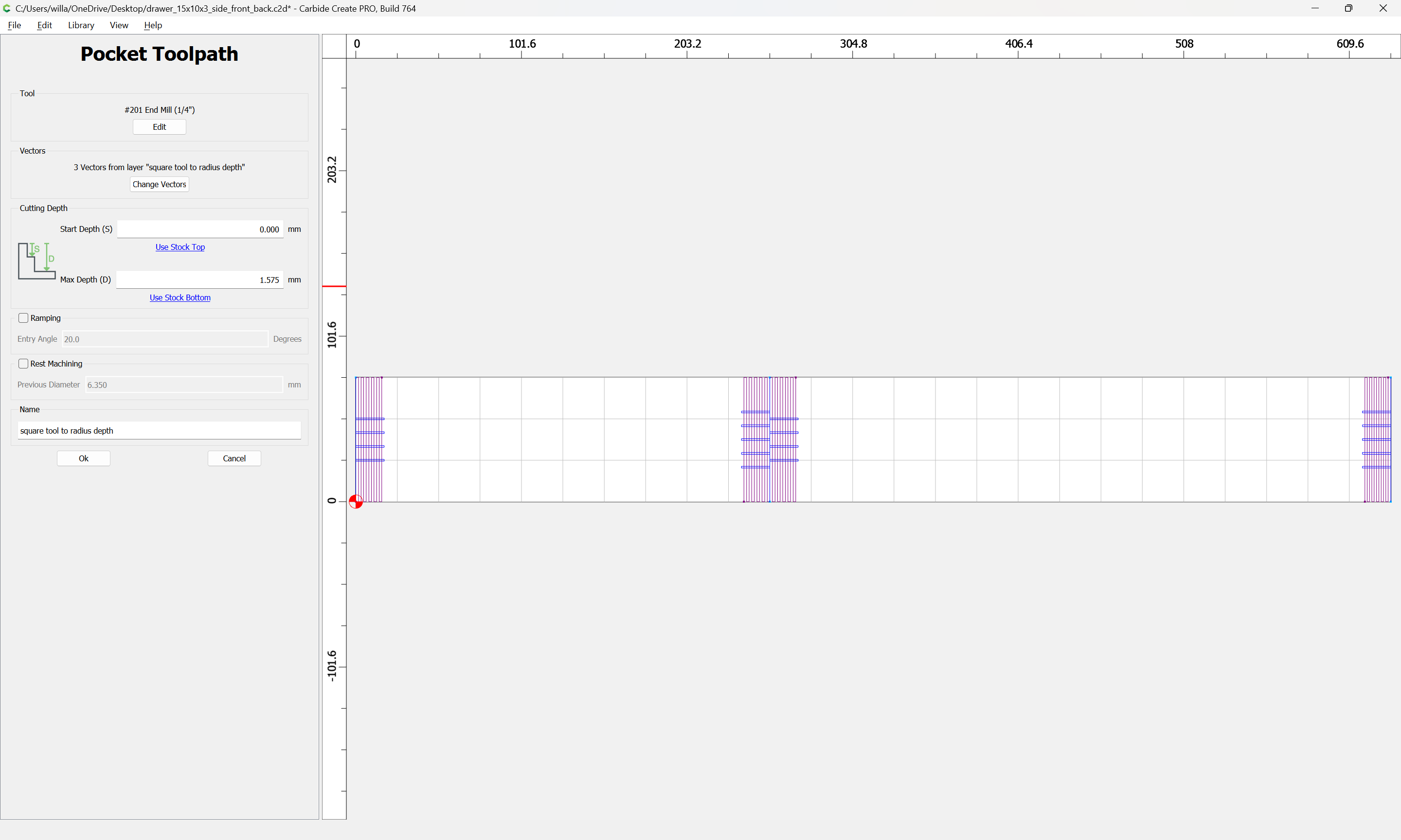
Note that in order to make this more manageable, it will be better for each to be positioned so that the toolpath depth can be specified in terms of the Stock Thickness, which fortunately is how things were positioned:

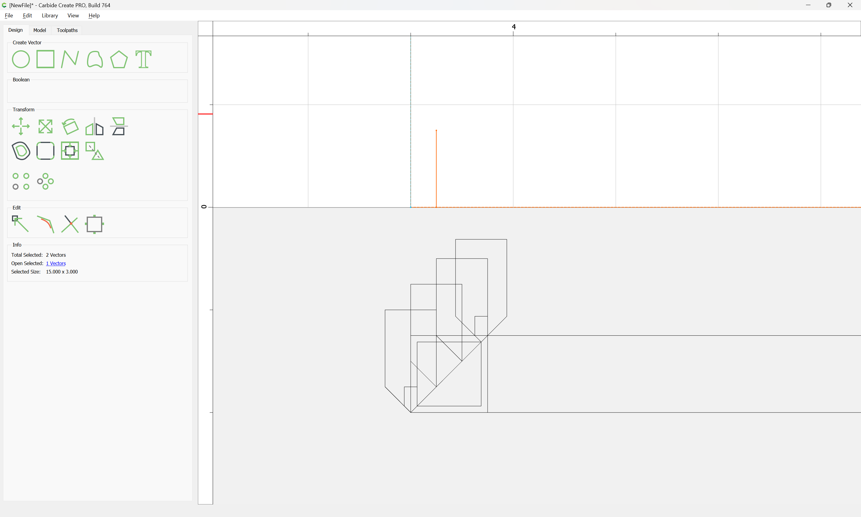
and it will also be necessary to cut using the V to full depth at the end of each joint:

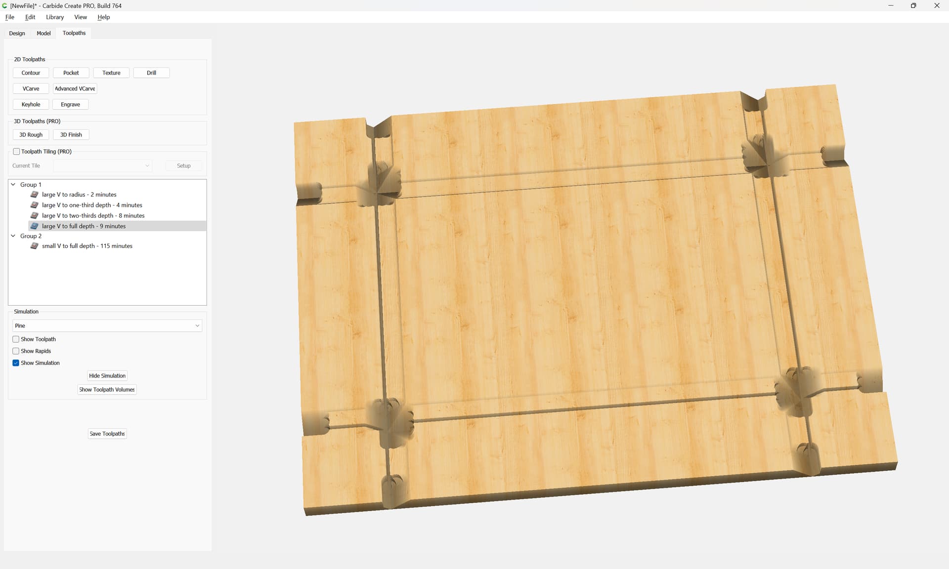
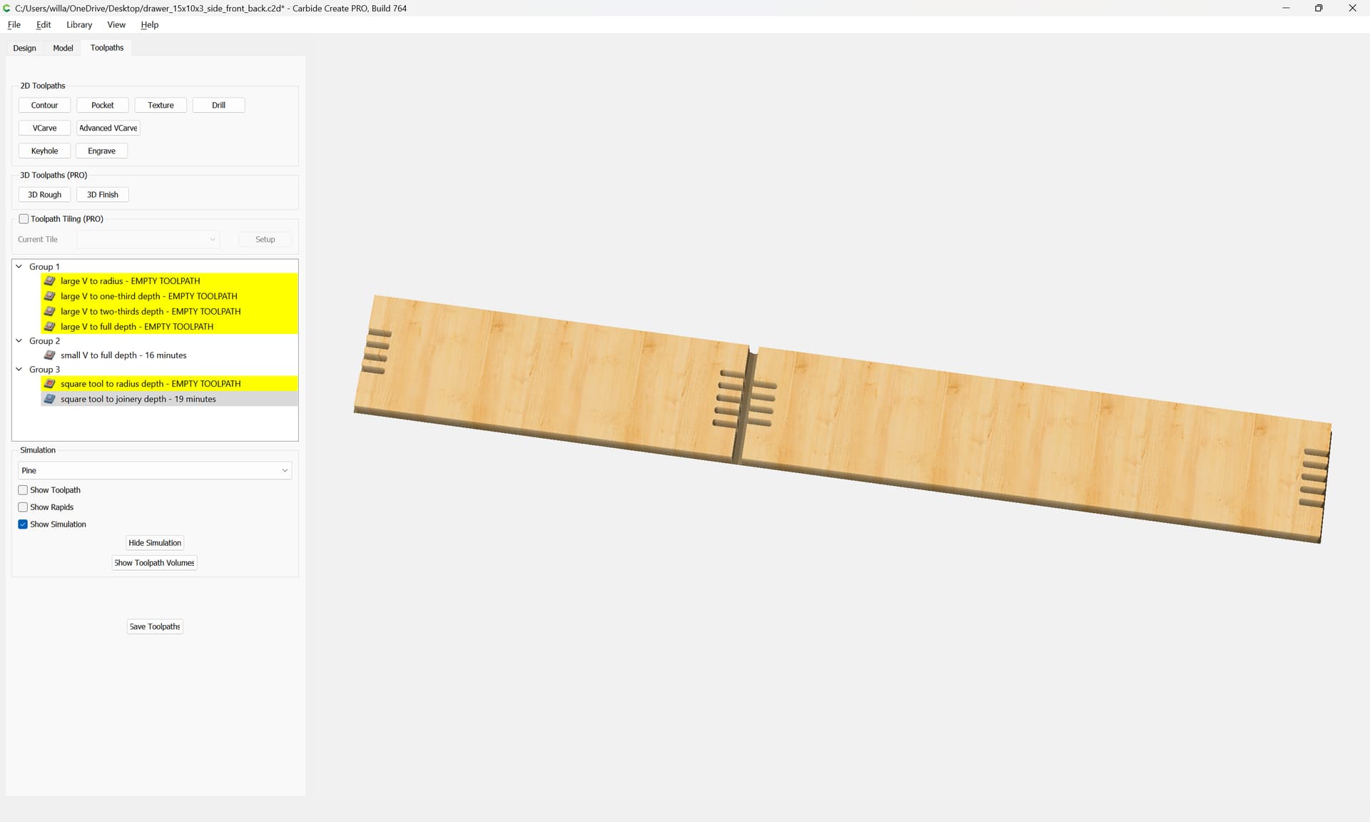
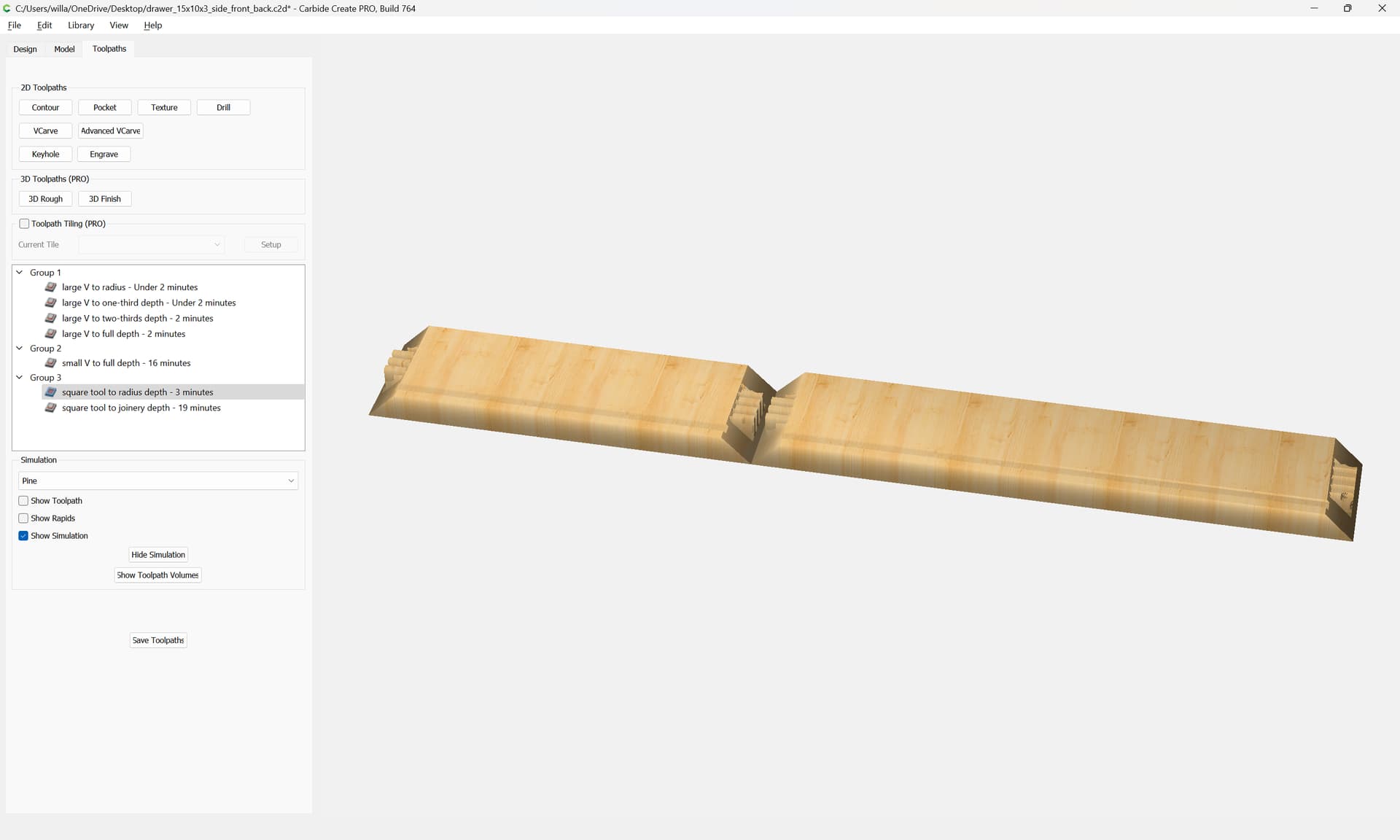
with a bit of adjustment there are toolpaths for each depth which cut as:

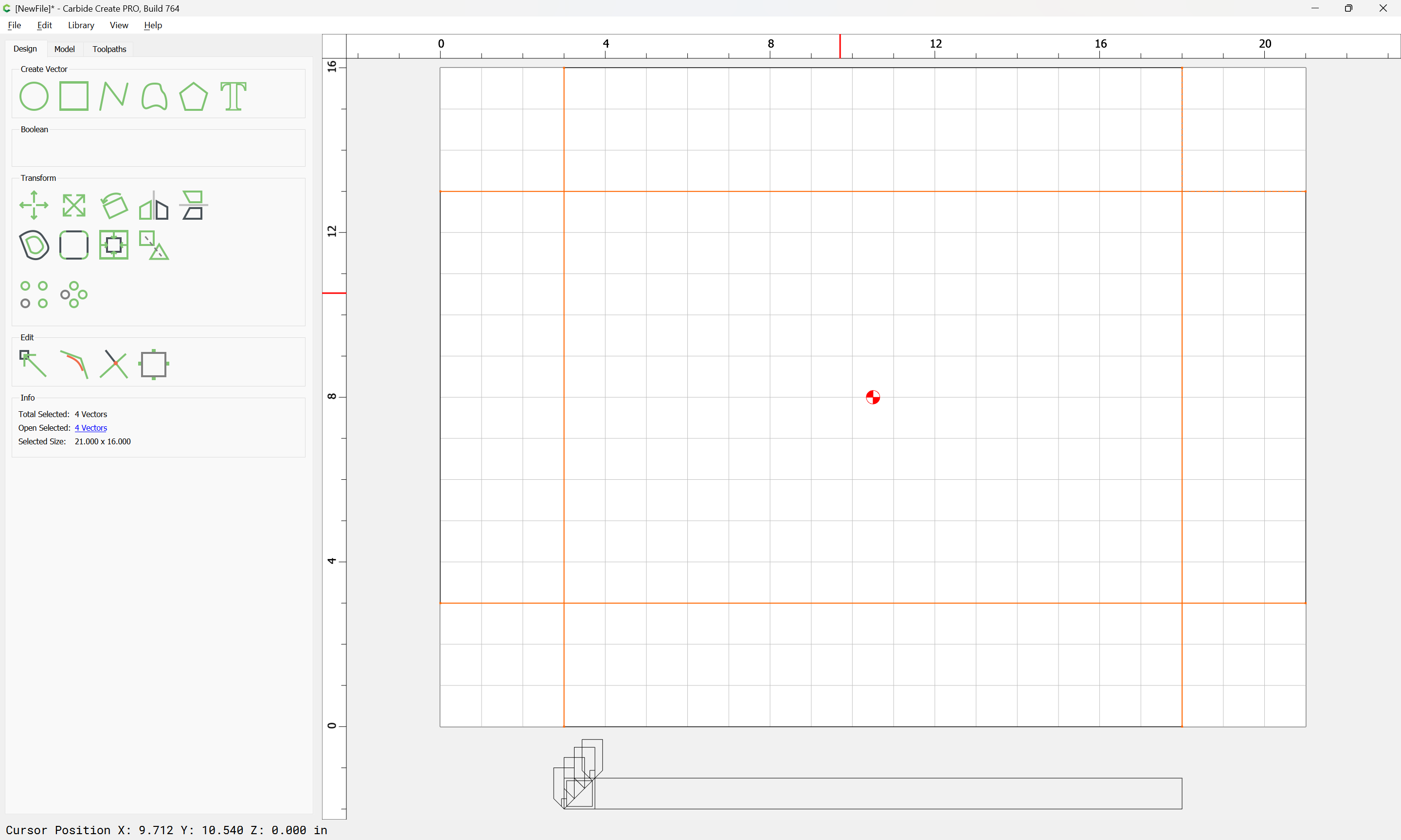
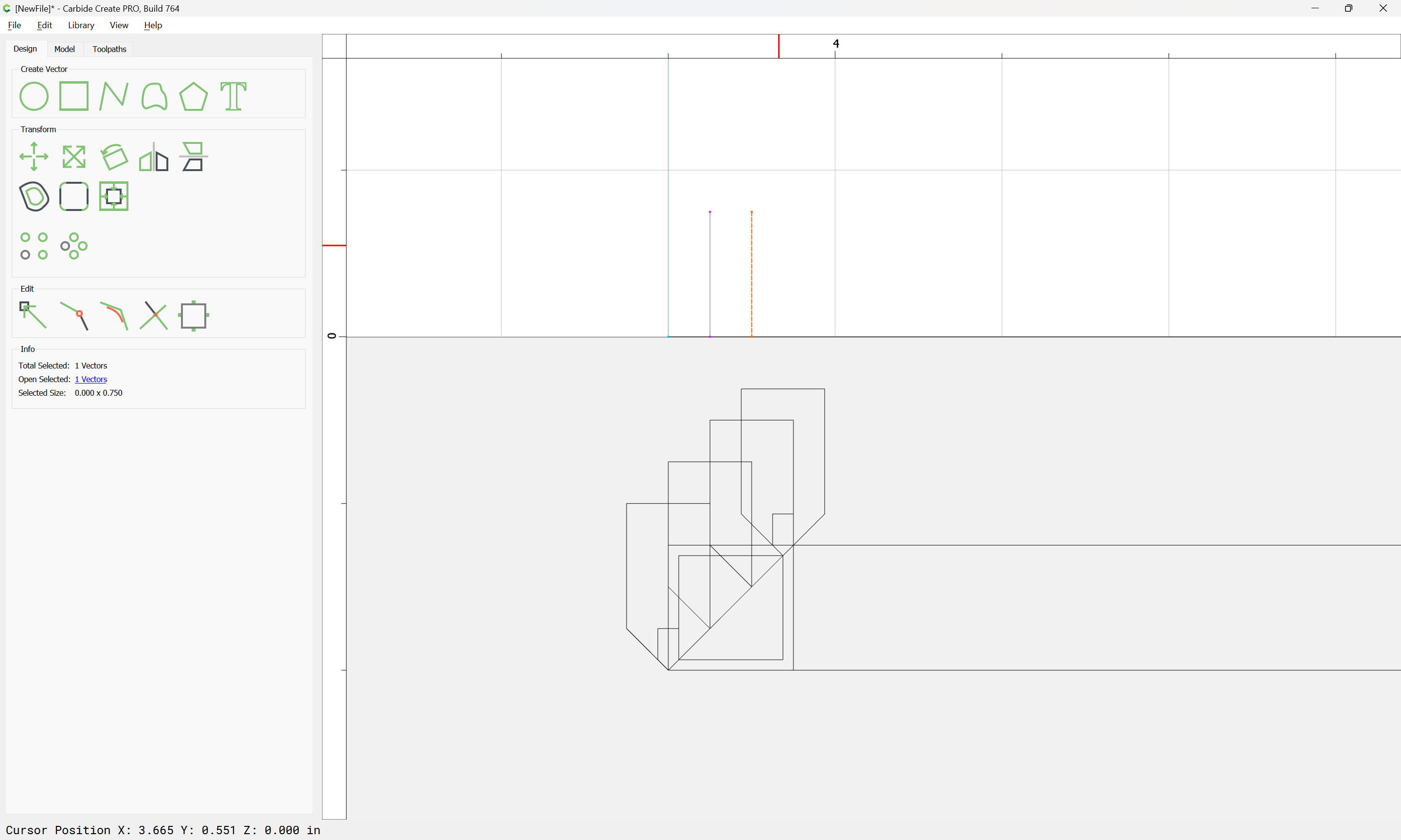
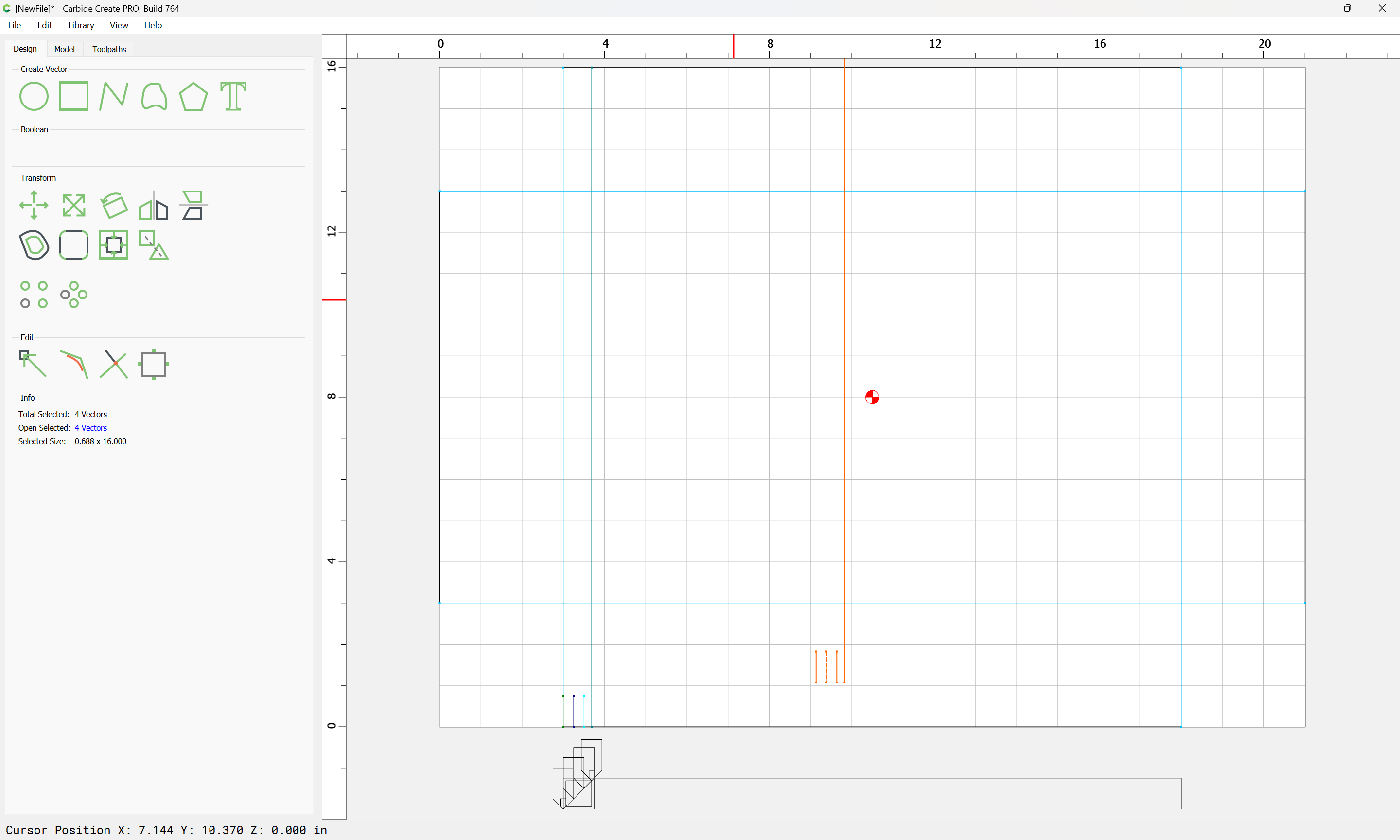
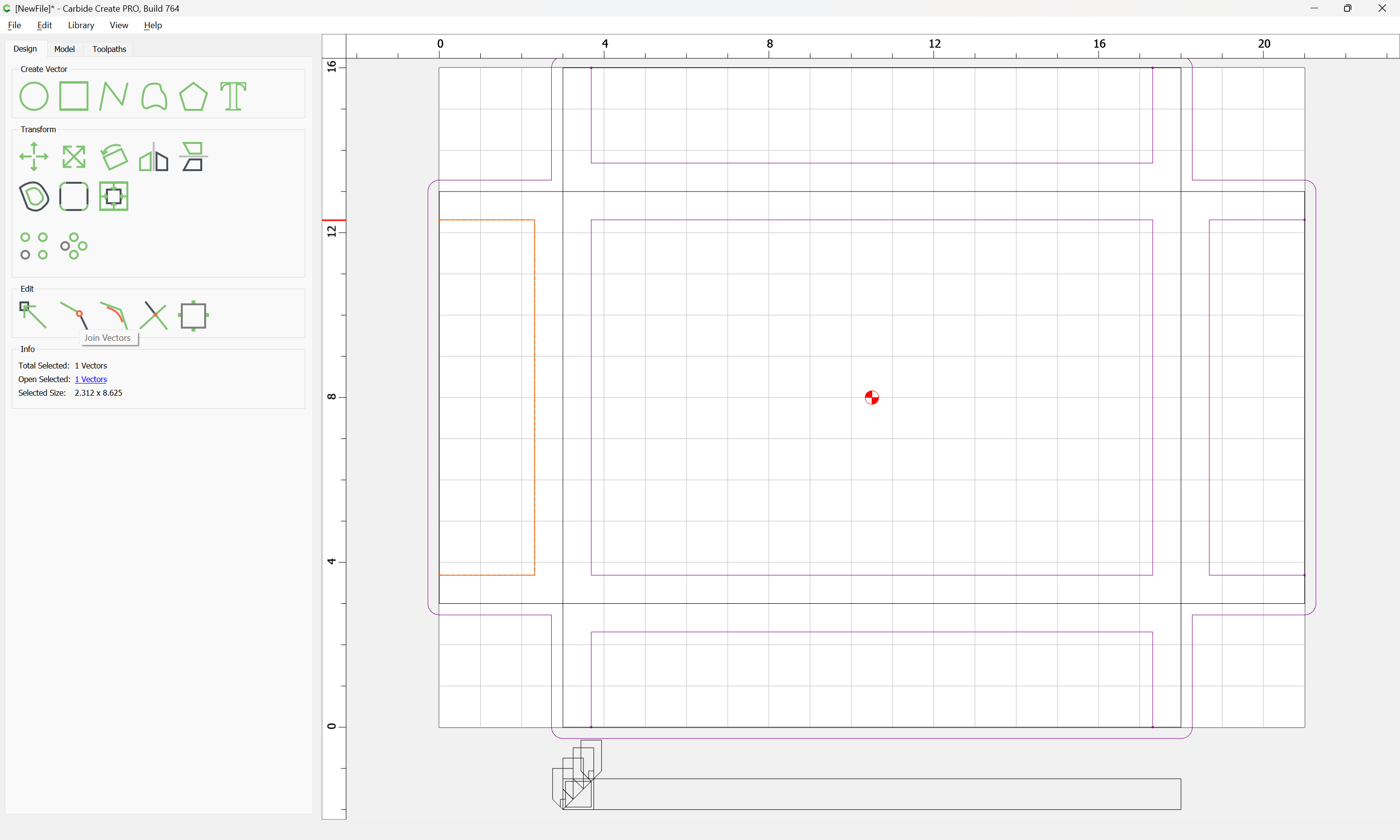
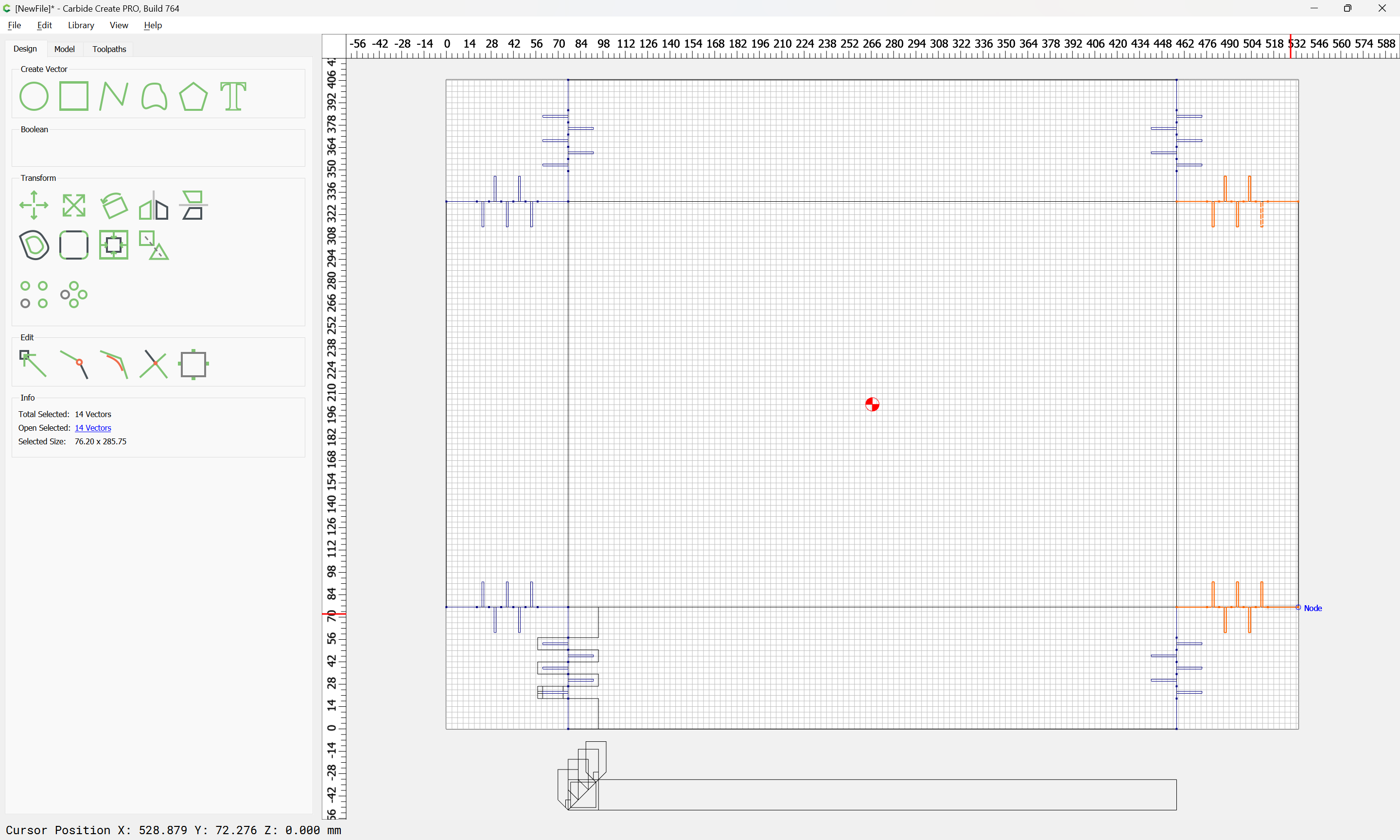
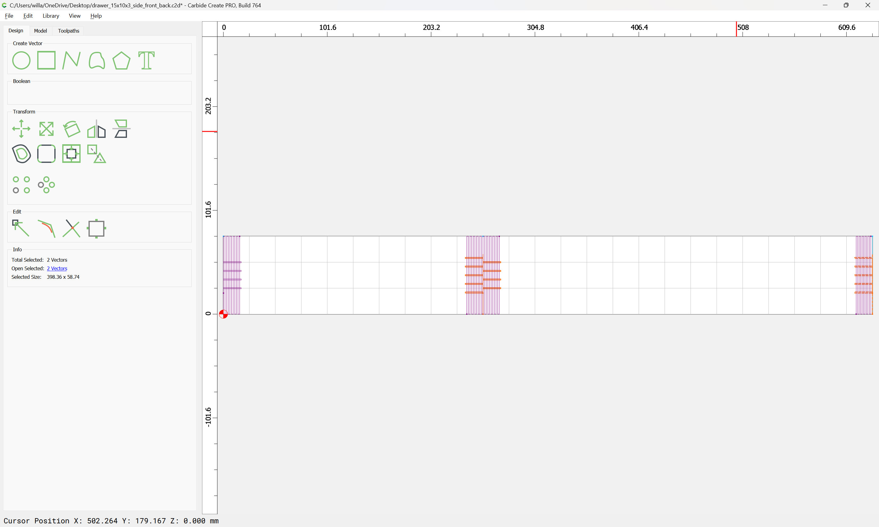
It is then necessary to select and replicate the geometry at the beginning/end of each joint:

and it will be necessary to re-assign the layer assignments so as to arrive at:
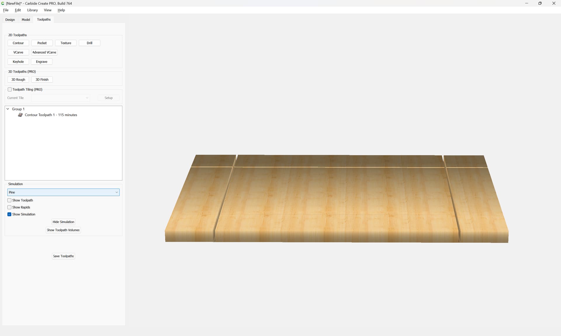
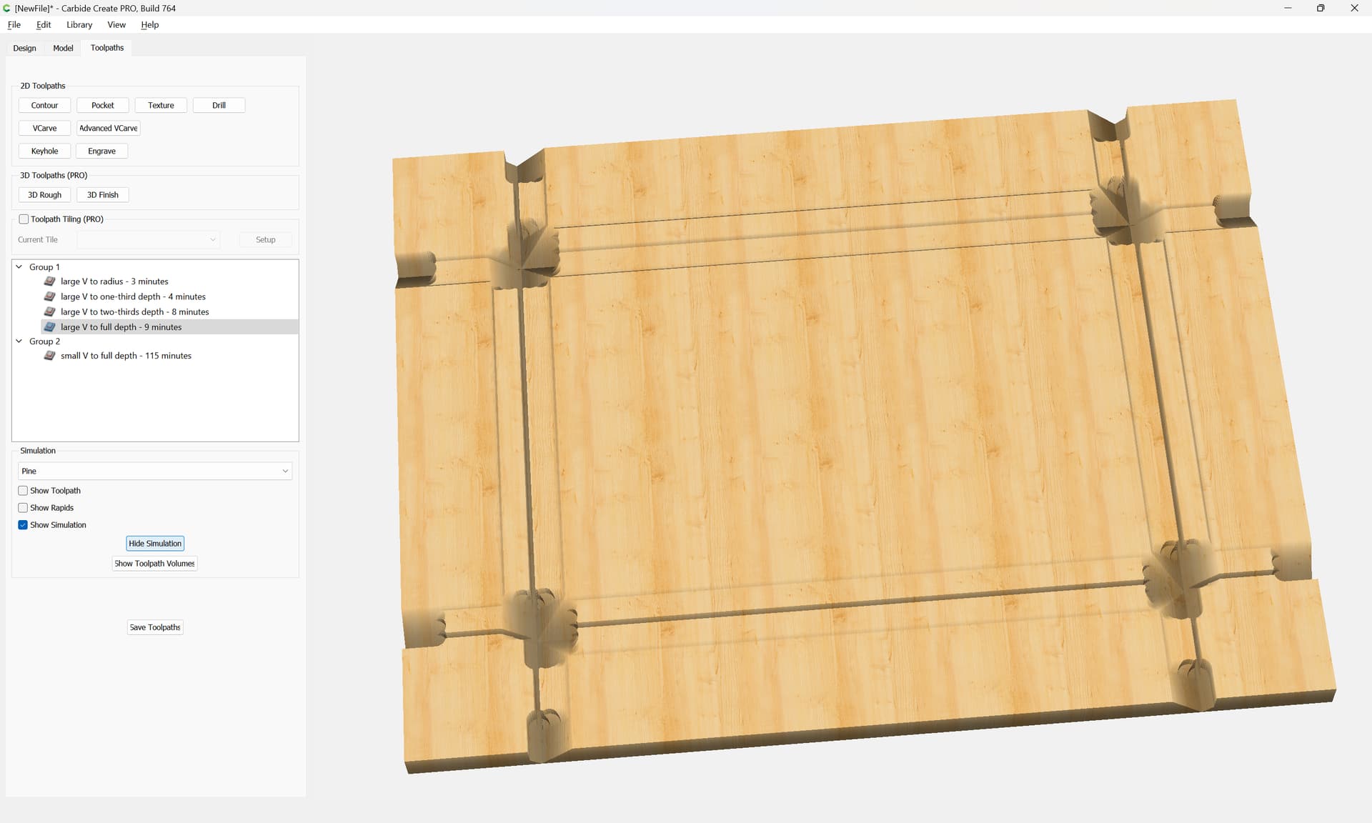
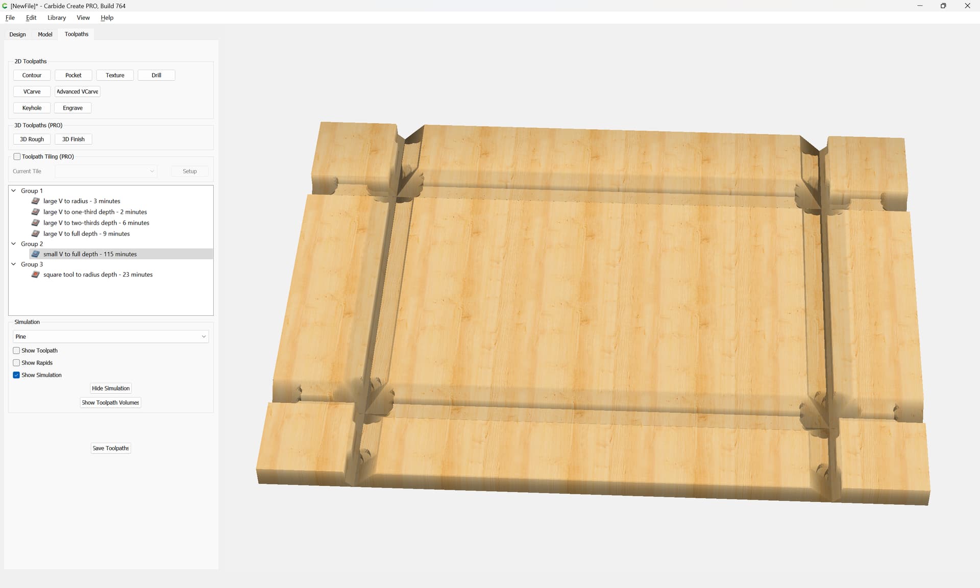
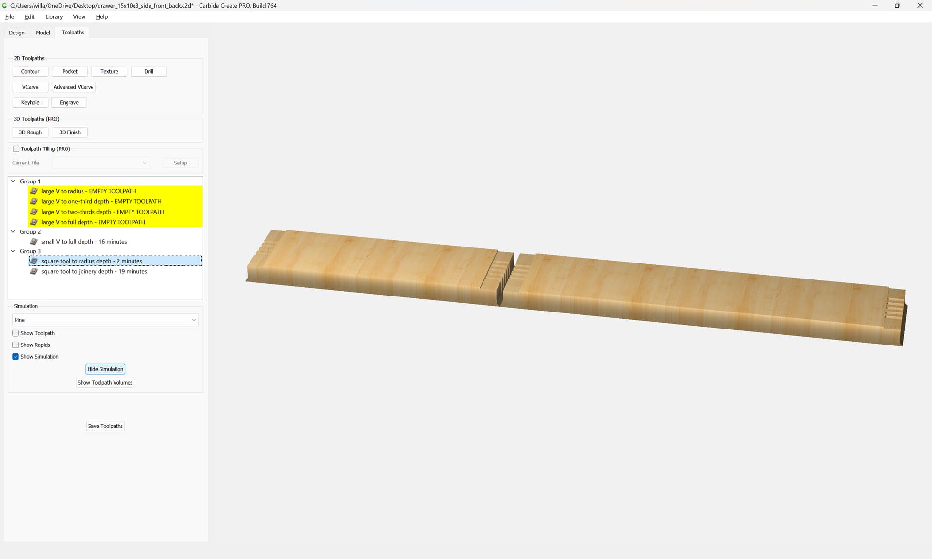
which previews as:

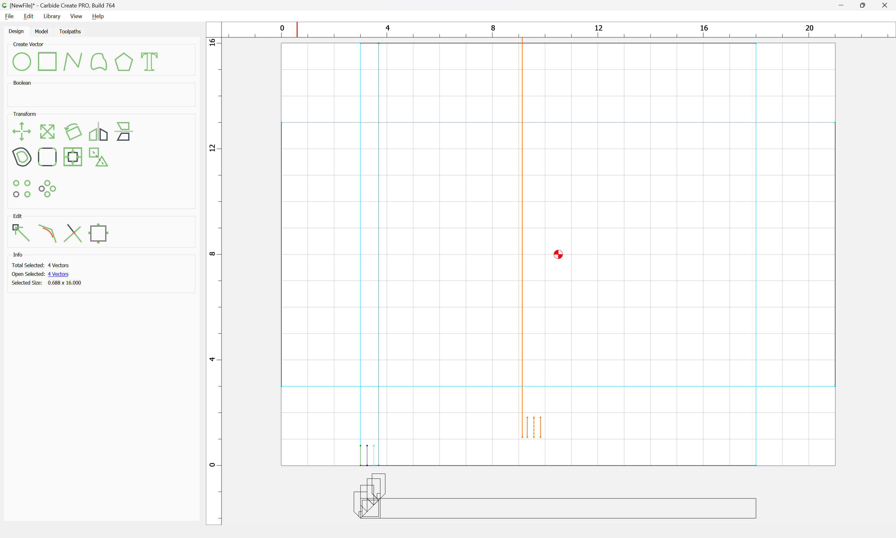
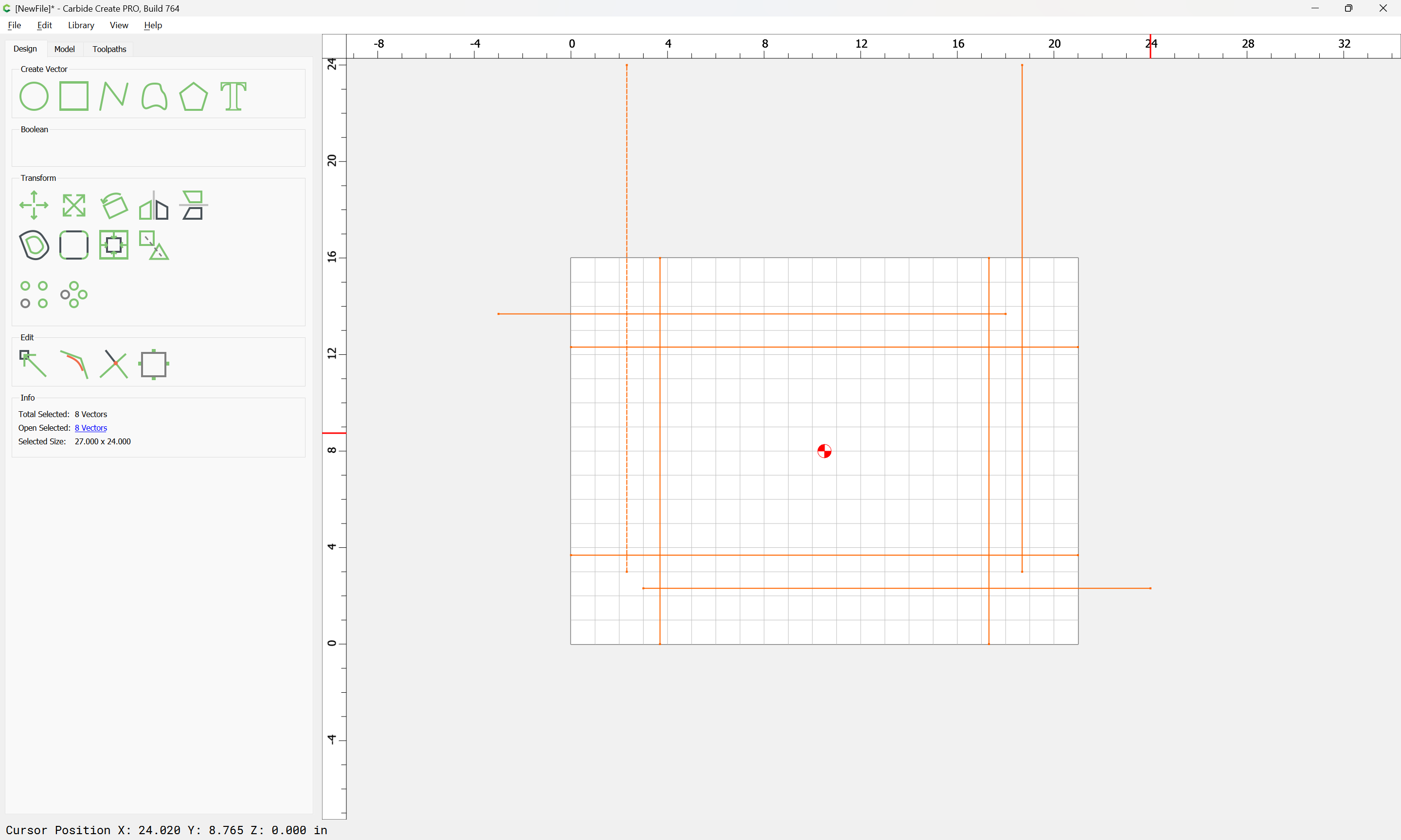
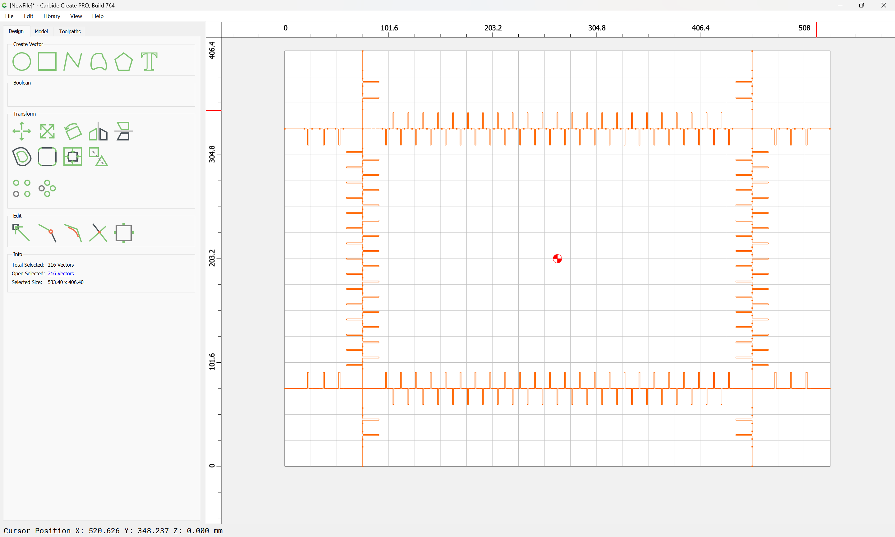
which wants a few more lines:

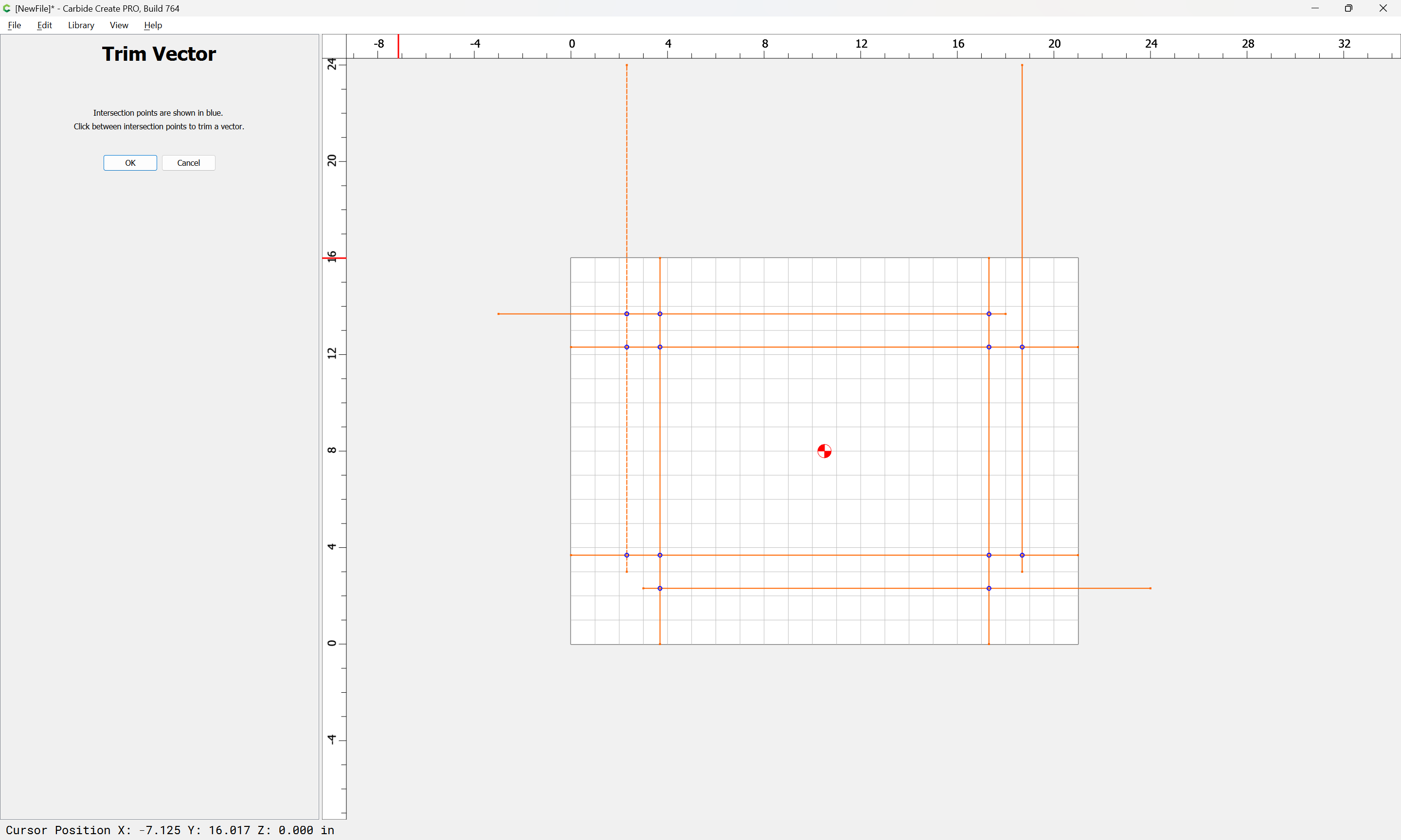
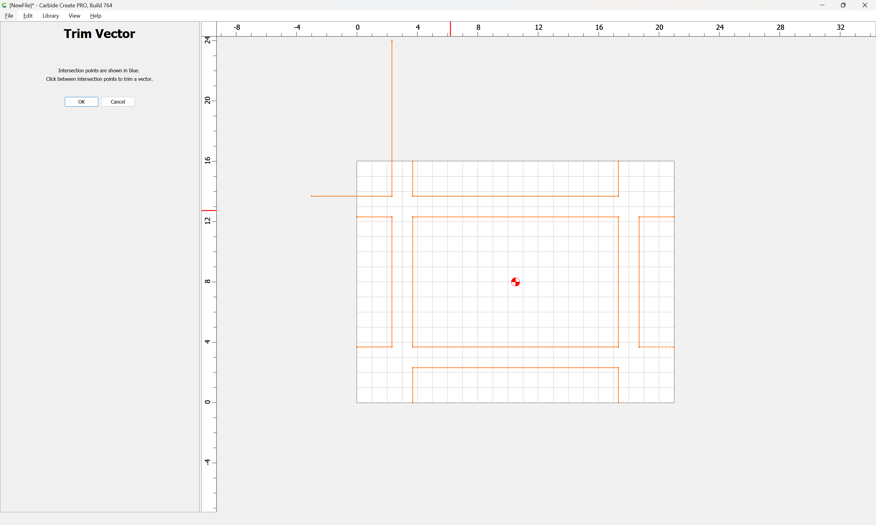
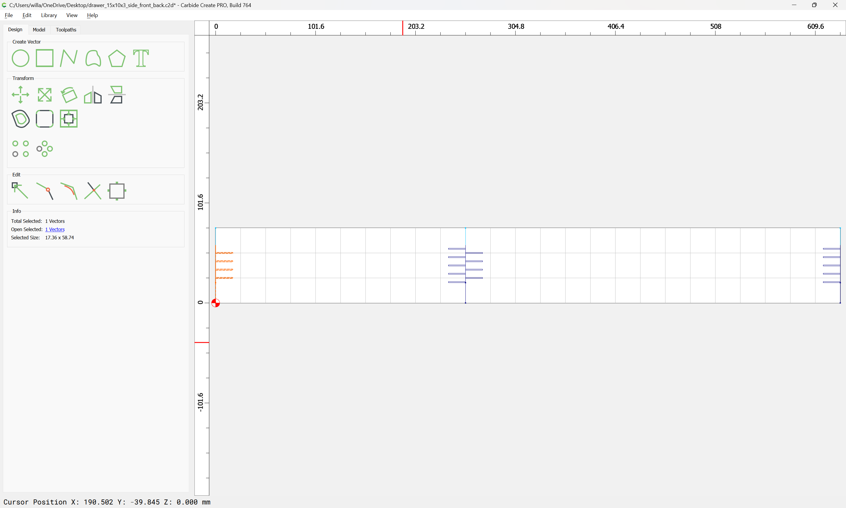
but note that many, so Trim Vectors:

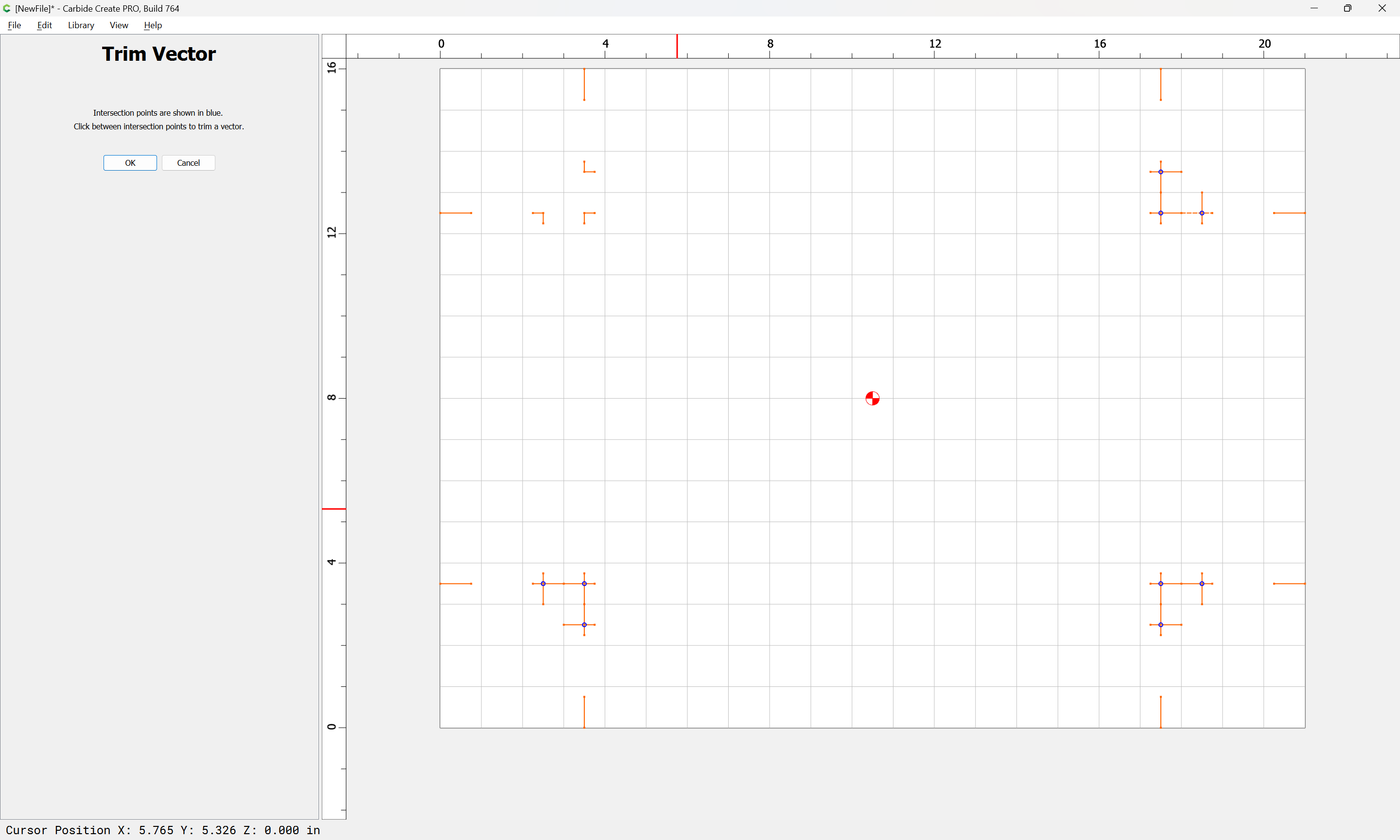
and remove the lengths which are not wanted:
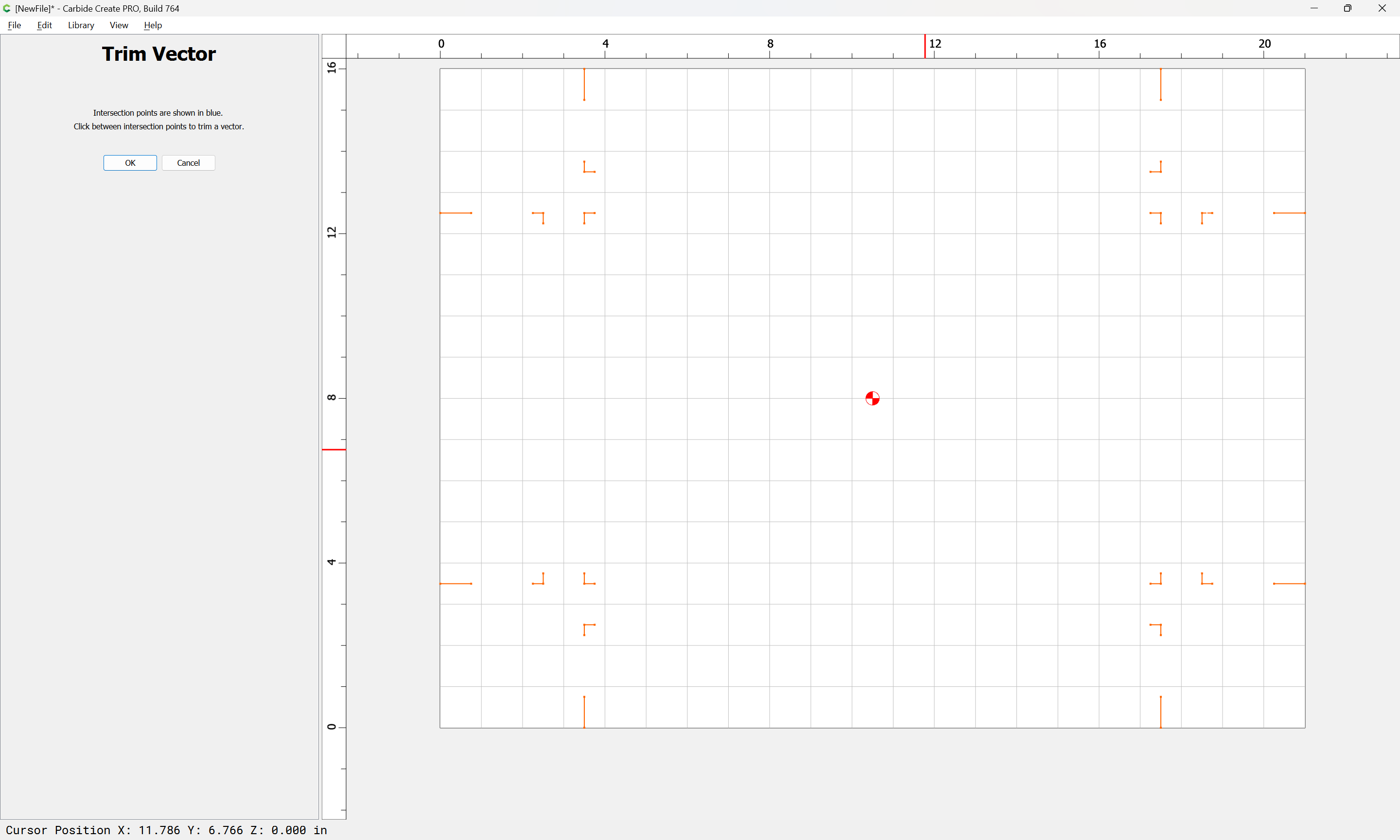
for each cut depth:

Eventually arriving at:

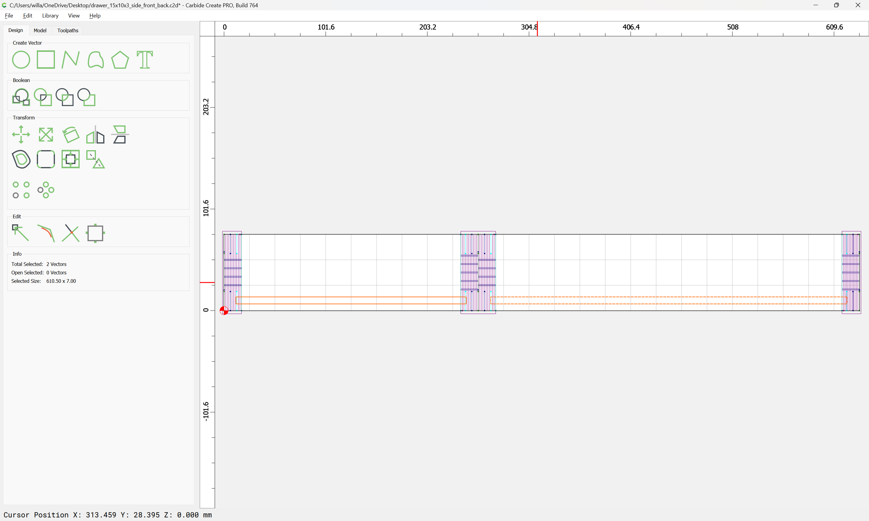
It will be necessary to cut out the perimeter using a suitable tool:

delete the unneeded central area:

and geometry defining the uncut geometry will also be needed — this is easily made by duplicating and closing the large V radius depth depth geometry:

close each open geometry and create a toolpath:

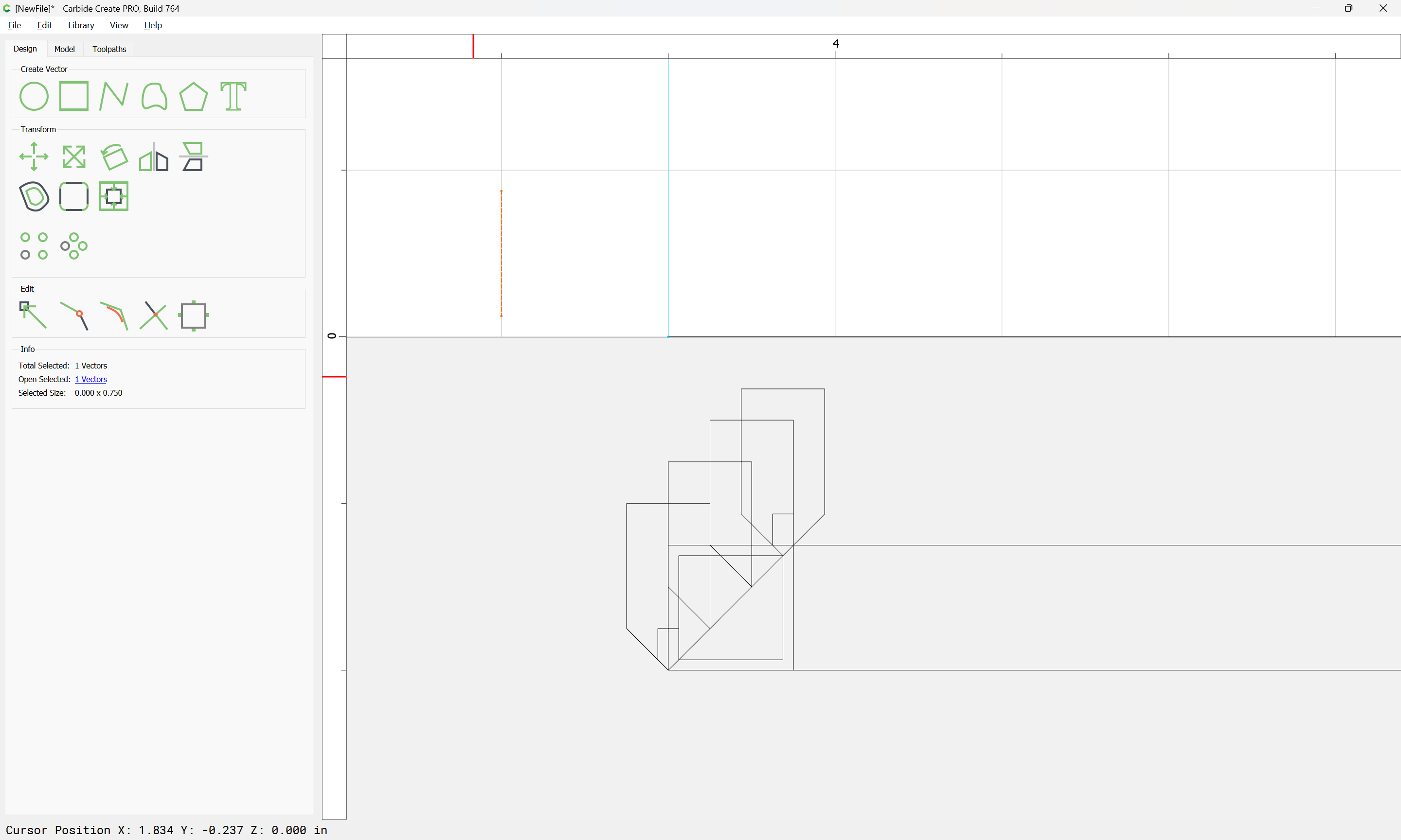
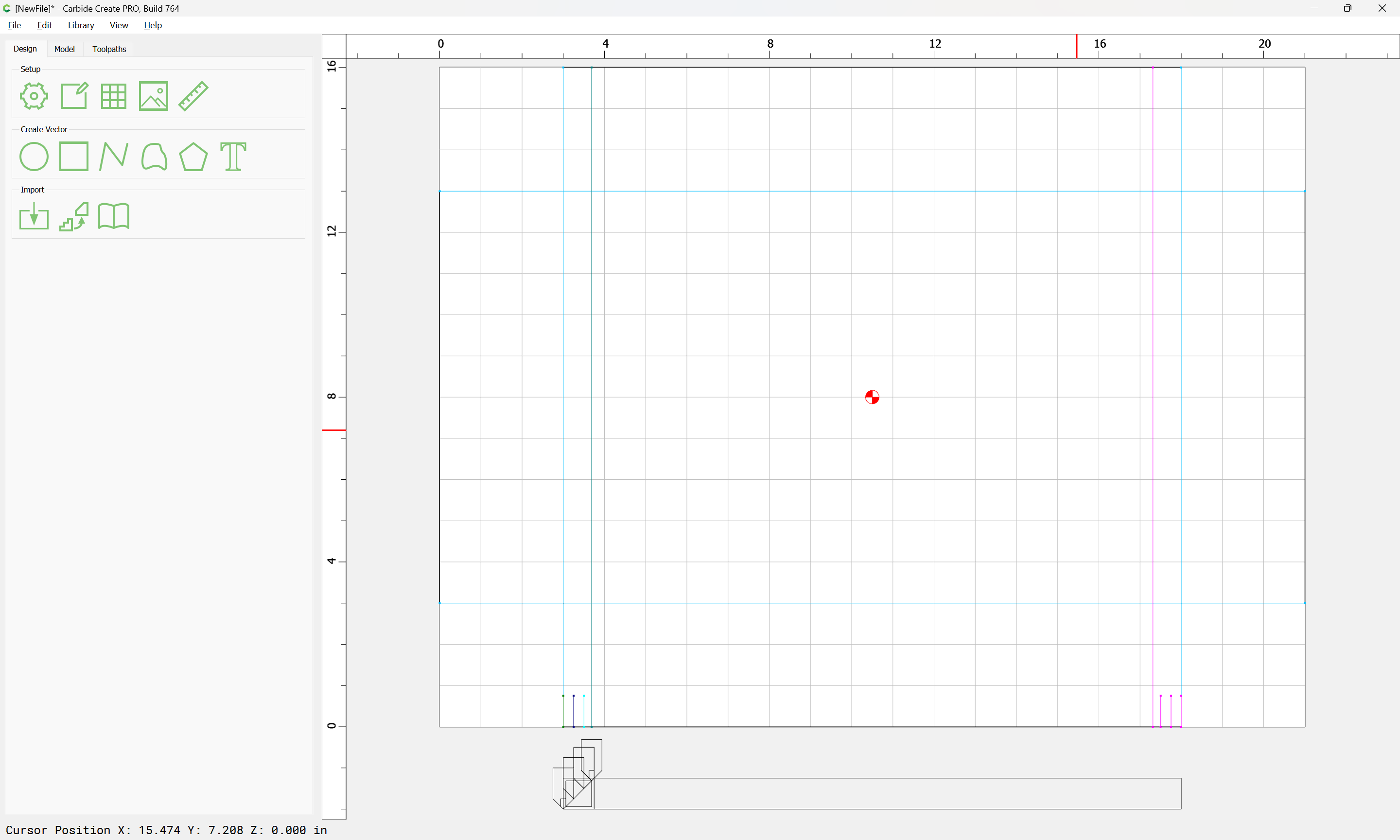
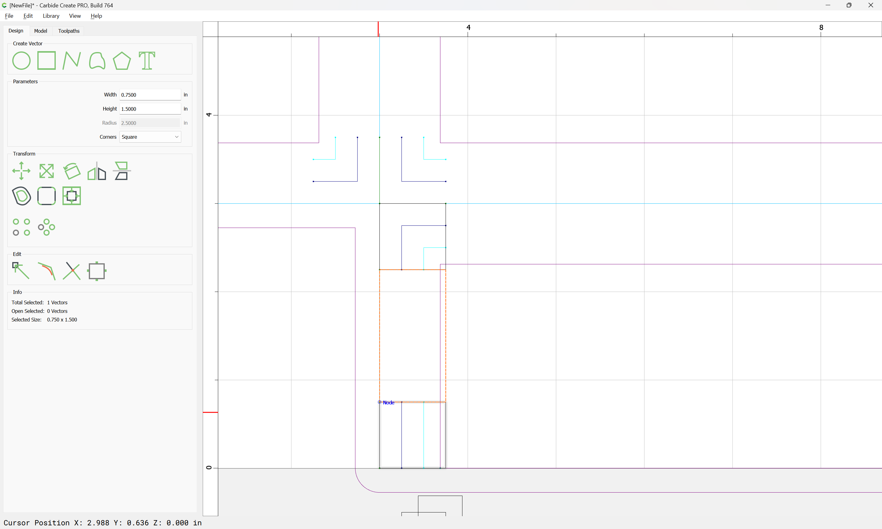
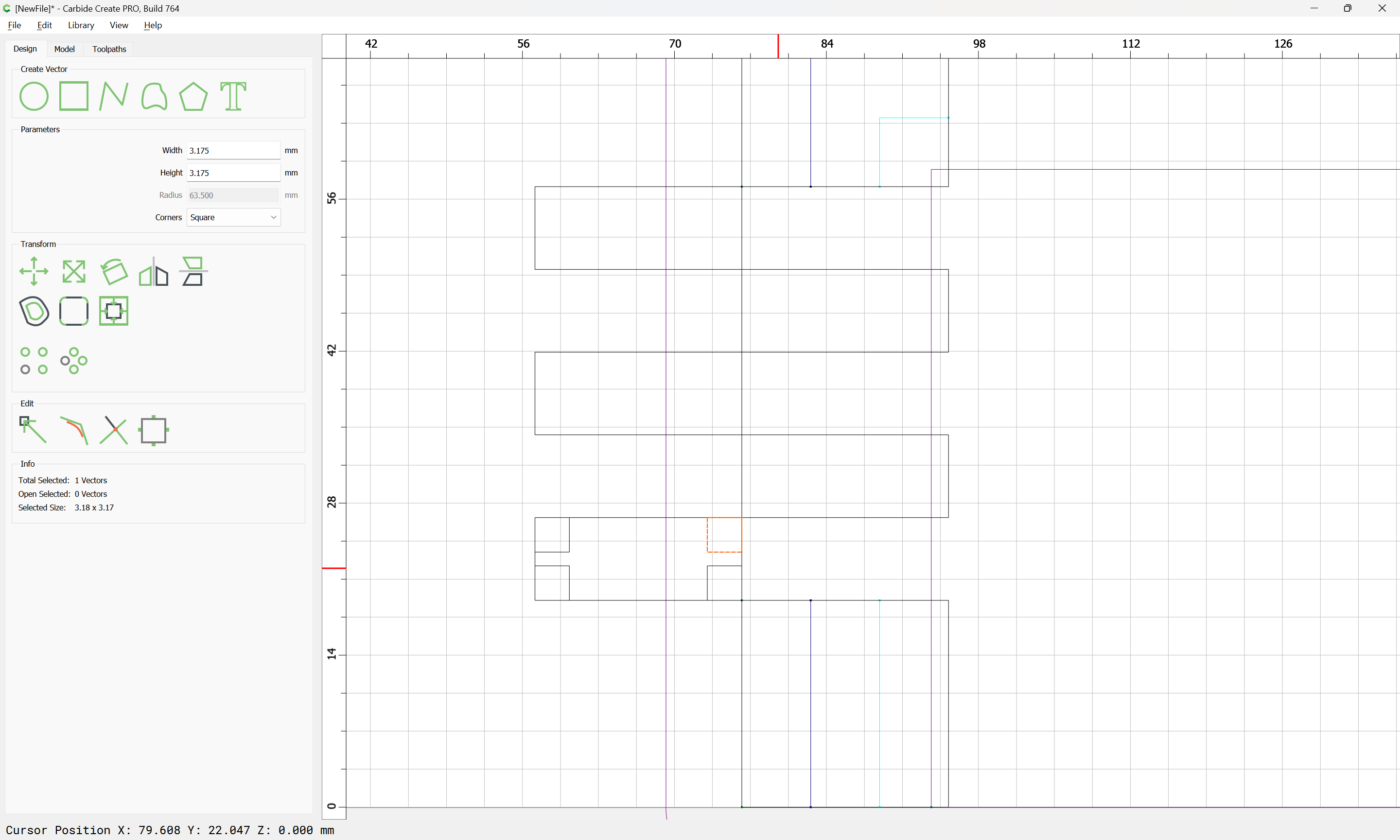
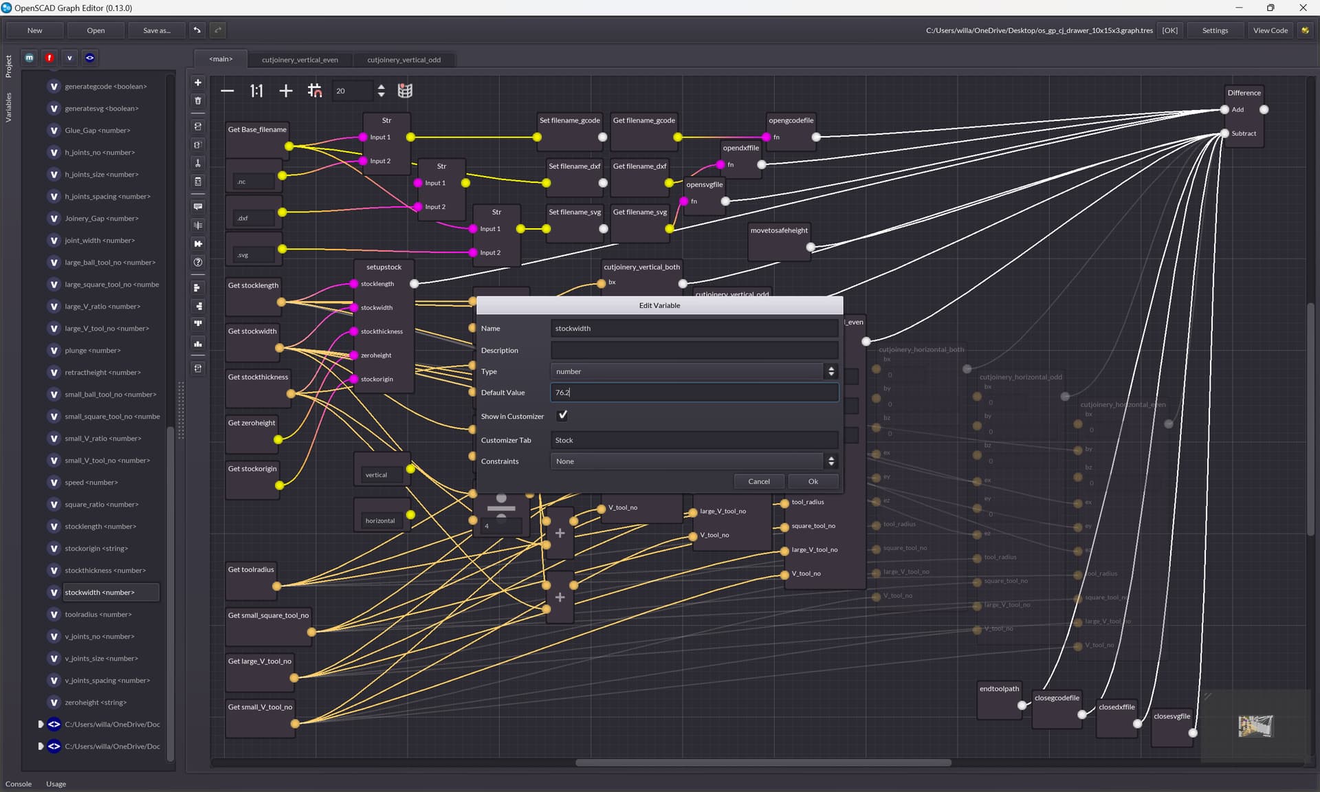
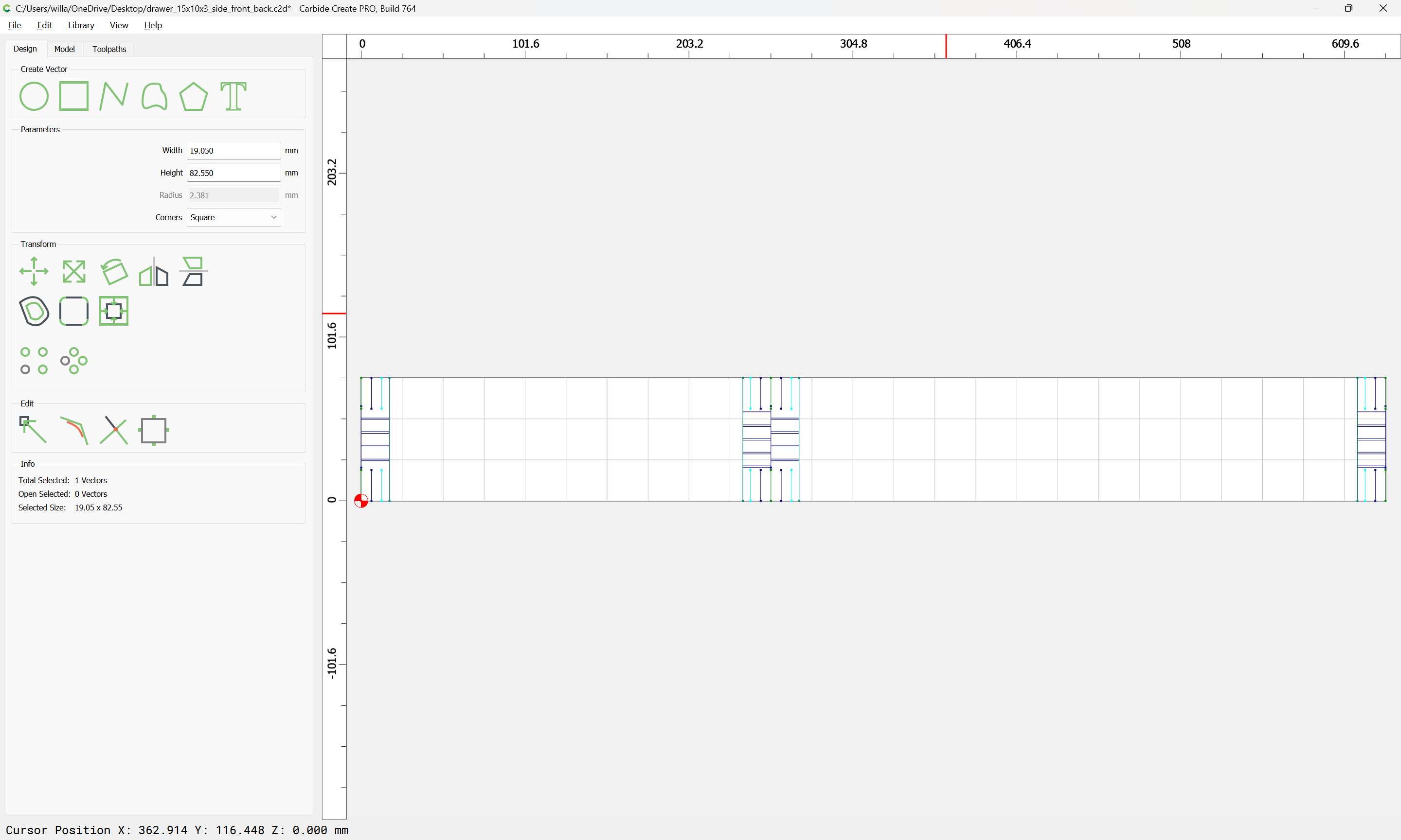
Lastly we need to draw in the geometry for the joinery:

which is easier in metric:

38.1 / 7 == 5.44285714

Rounding that down and dividing we get:
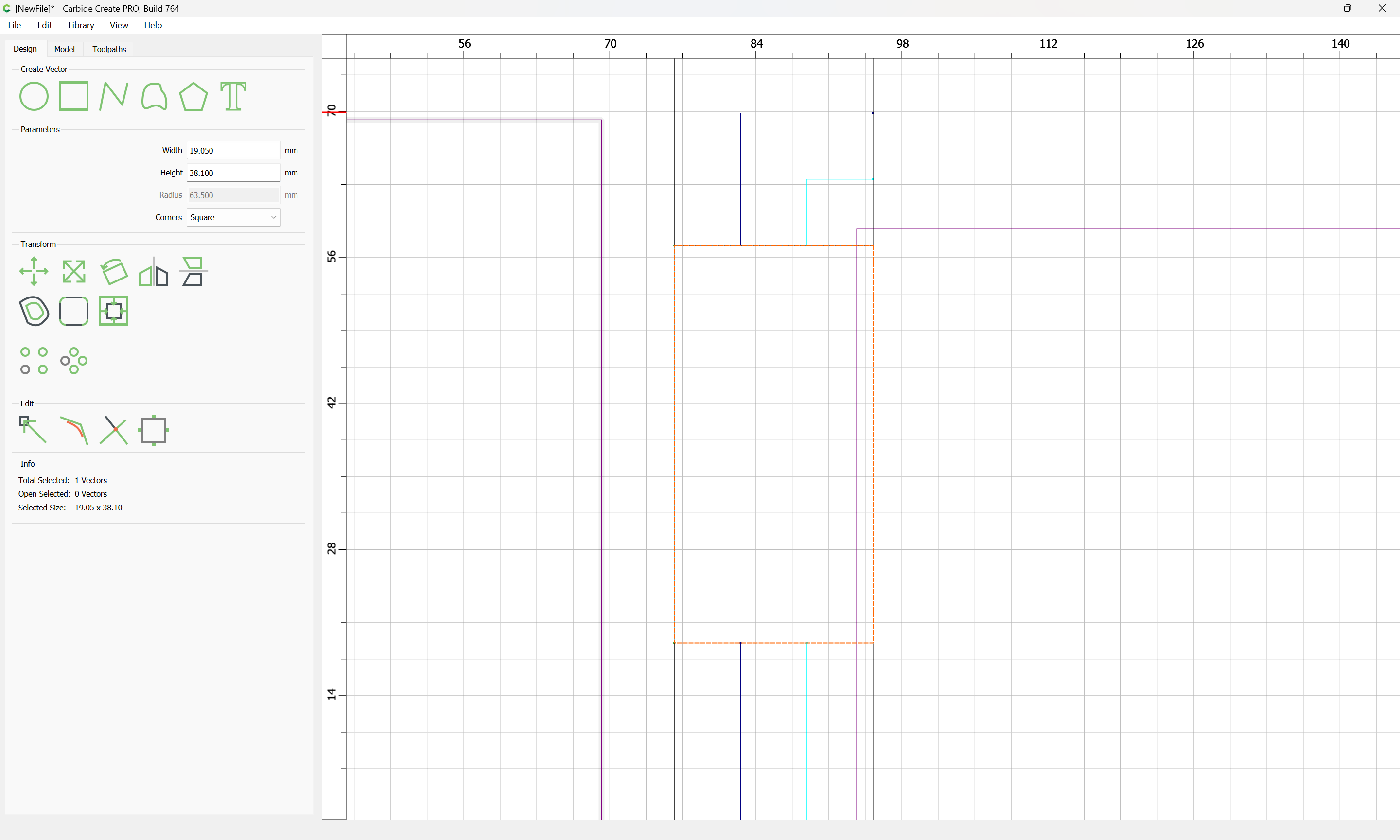
38.1 / 5 == 7.62

so we set the height to that:

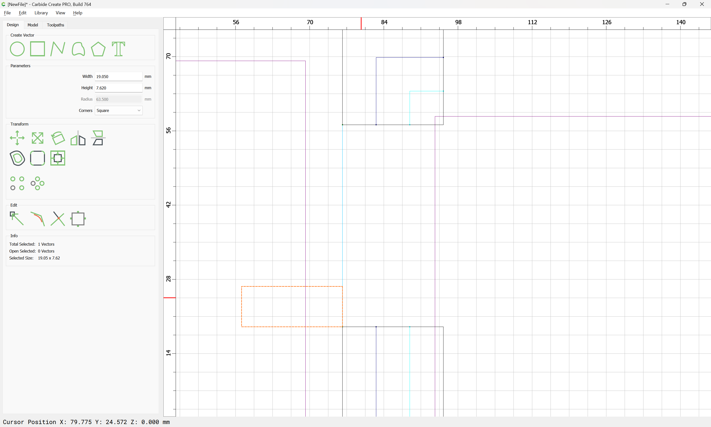
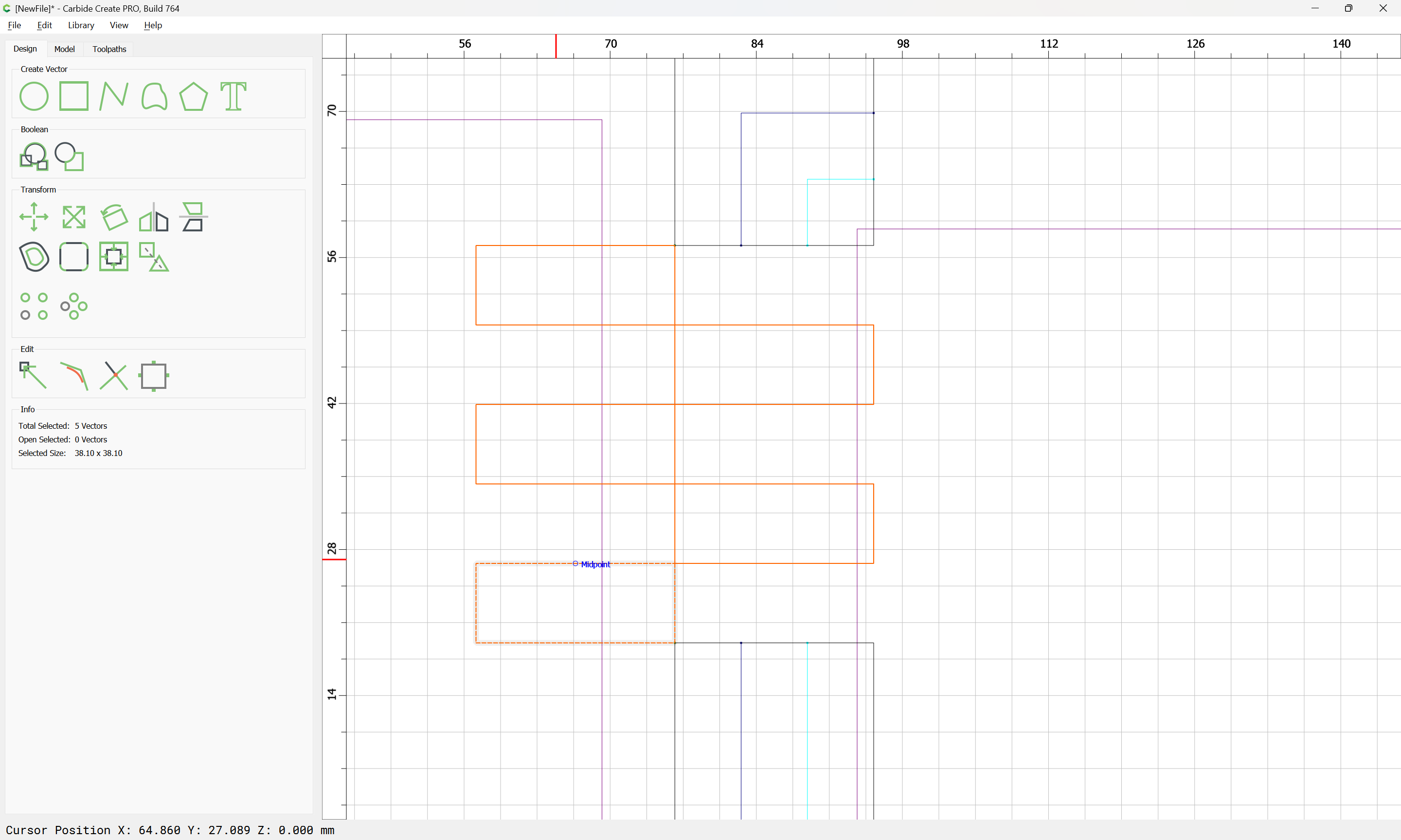
and arrange duplicates as necessary:

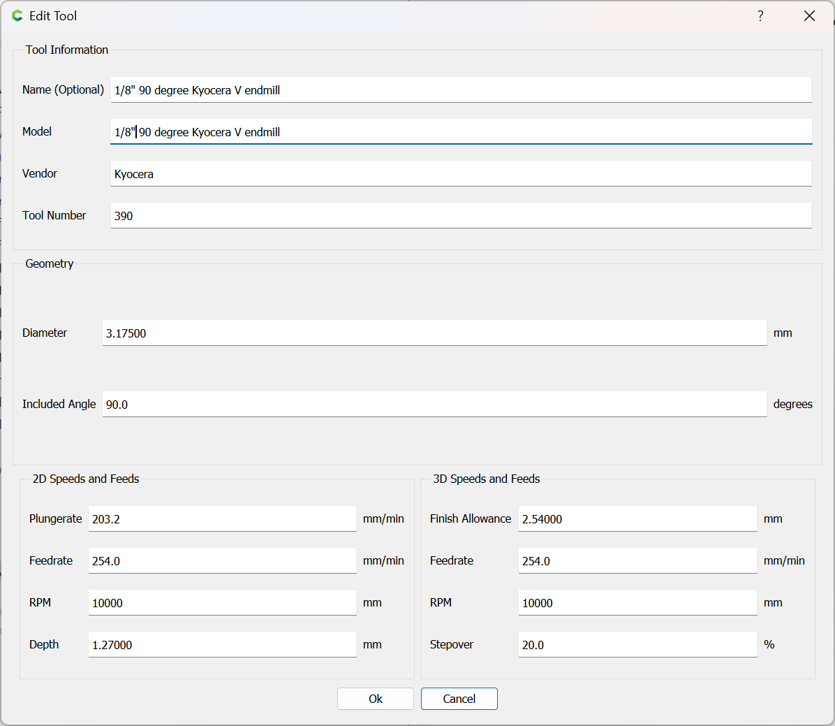
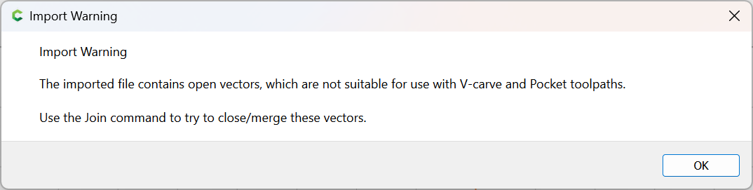
and it will be necessary to use a matching tool for the full-depth small V cutting.

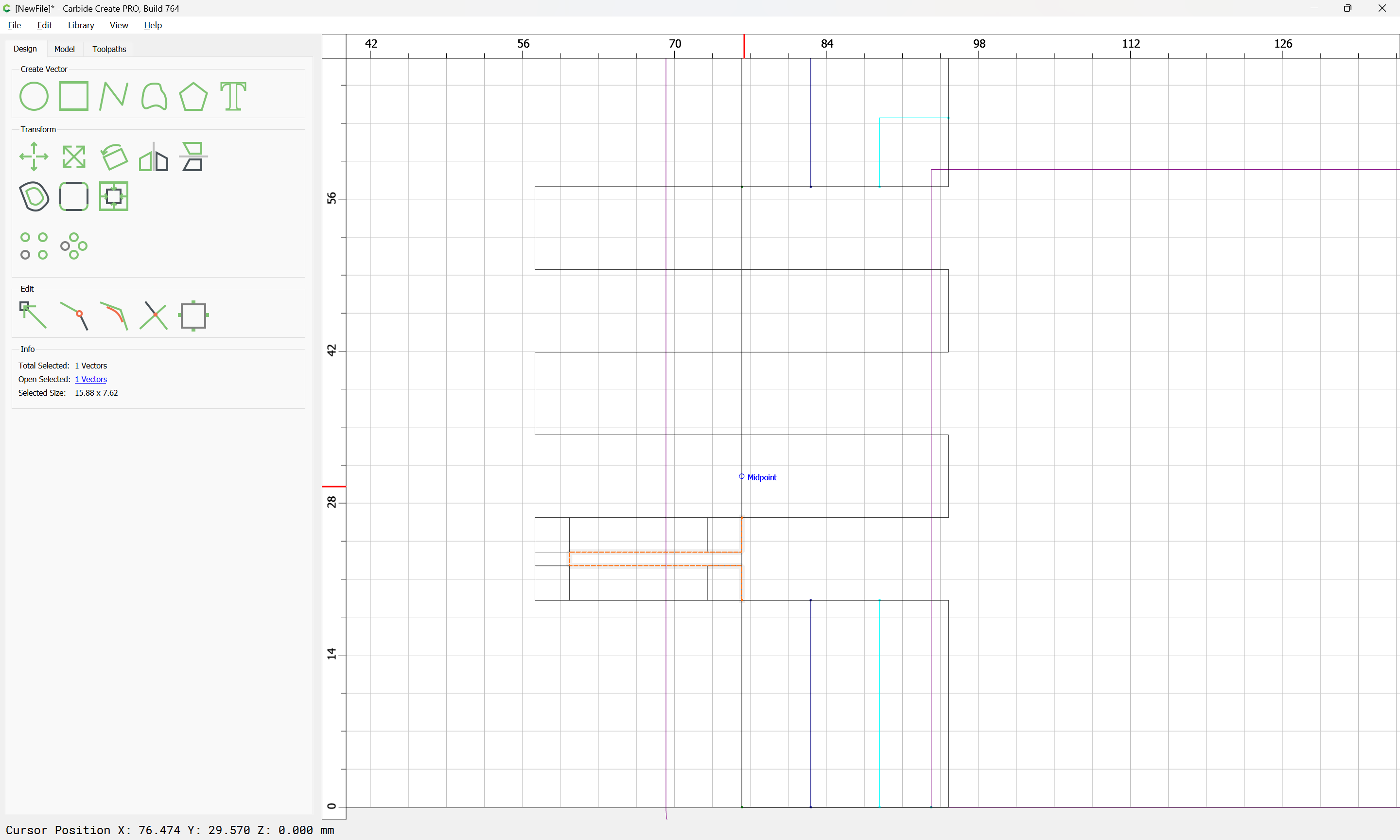
It seems to be easier to use a No offset contour for the joinery, so we draw in a polyline which would cut this:

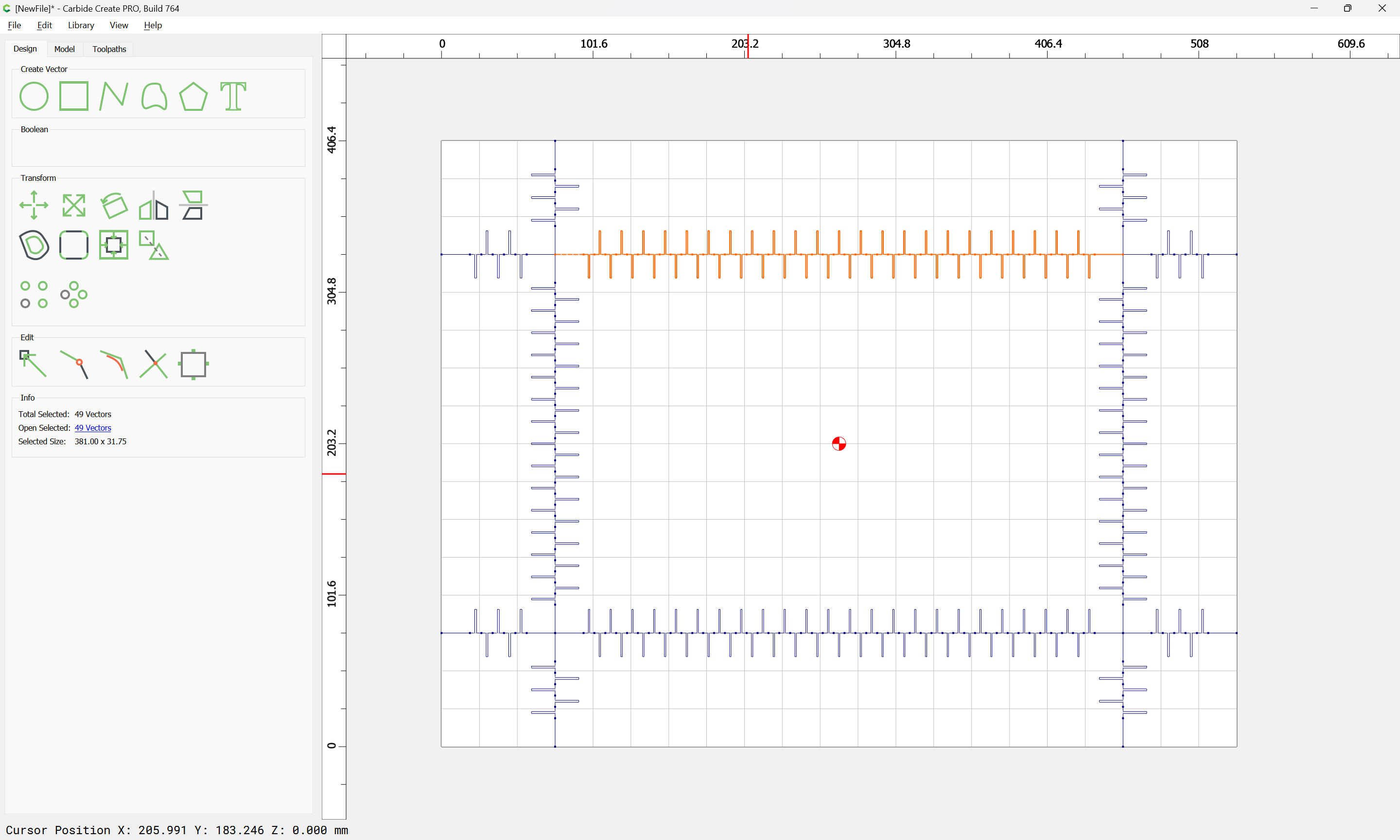
which we duplicate and stitch together with geometry at top and bottom:

and duplicate as necessary:

Repeating this for the joinery along the bottom:

We then want to remove the redundant joinery at the corners:

(and address the problem of the added curves)
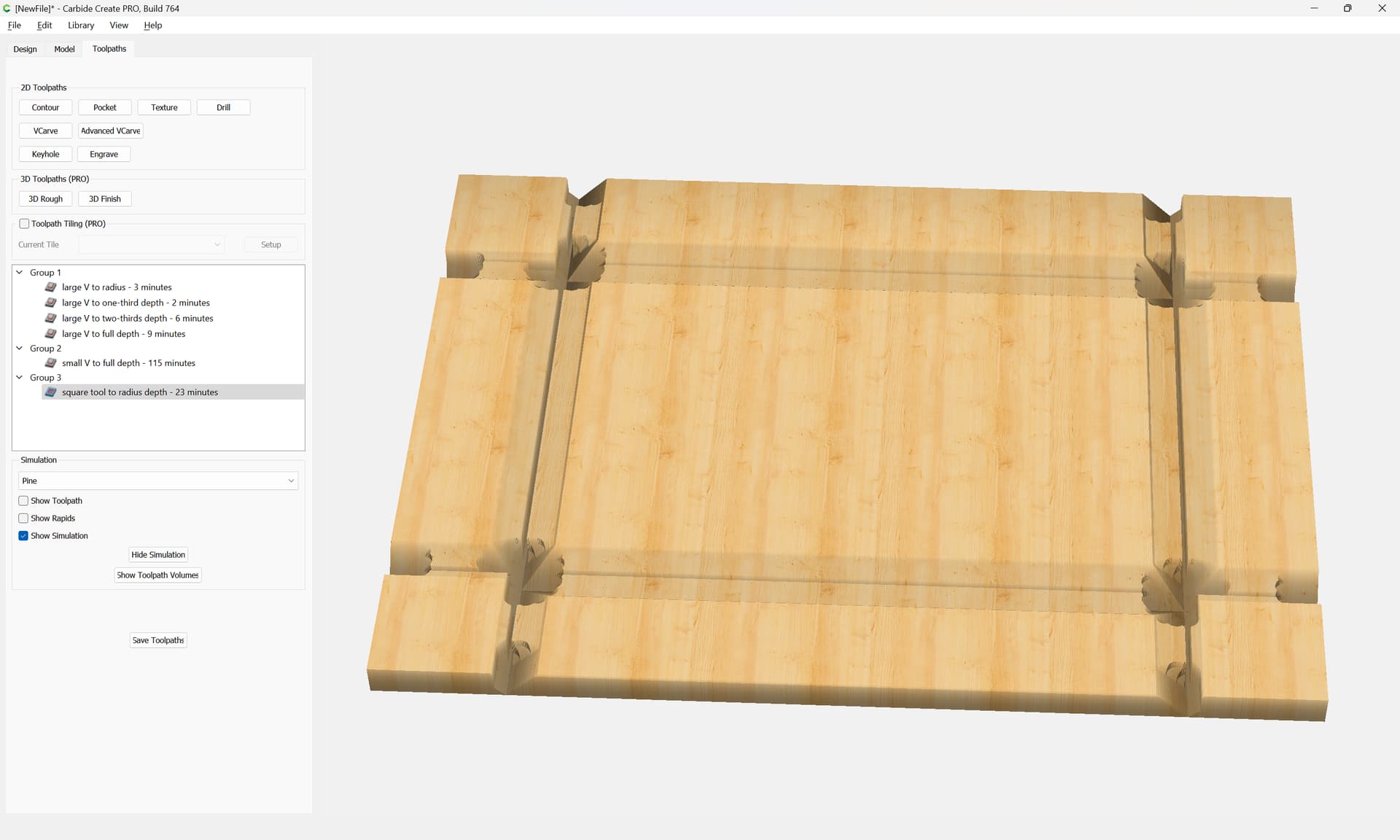
which previews as:

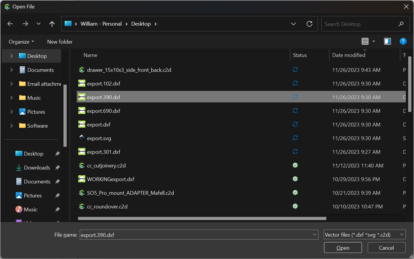
Attached as a v7 file:

drawer_15x10x3.c2d (272 KB)

1 Like

A more typical way to do this would be to instead cut the front/back and sides from a board, then use a piece of plywood in rabbets as a bottom.

The easiest way to do this is as a file which has one side, and a front/back part and which is cut twice — drawing it up in Carbide Create we get the dimensions:

which are easily transferred into a file for OpenSCAD Graph Editor which implements this style of joinery:

and when we add the dimension for the position separating the two parts:

We get:

which yields a couple of files which can be imported into Carbide Create.

One thing which is left undone is drawing in rabbets for the bottom — this is easily done in Carbide Create

When importing files, it is easiest to activate the appropriate layer:

Then select the appropriate file:

Import

Open

OK

which we can check the preview of:

and then we do each other file:

Note that certain files will need to be split:

Adjusting the tools we arrive at:

Note that tools and toolpath type need to be adjusted to match, or geometry modified:

Continuing, we import the Large V tools:

Select objects which need to go to specific layers:

and adjust/duplicate other geometry for other depths:

to arrive at a 3D preview of:

Lastly we draw in geometry for rabbets for the bottom:

Naturally, the depth would be adjusted.

This topic was automatically closed after 9 days. New replies are no longer allowed.