Cutting Thick Acrylic

There will be heat produced in cutting. Much of it is in the chip. If the chips clear well, the heat goes with them. .

The low thermal conductivity has little to do with it. If anything, the low thermal conductivity makes the situation worse, as the chips don’t readily lose heat to the surrounding material and get soft and sticky. They need not melt to foul the tool. If they clear well, then it matters not if they are soft and sticky.

2 Likes

Because I get good results.

3 Likes

Isn’t the heat produced at the cutter - workpiece interface? How does “much of it” get into the chip (even with workpieces like aluminum that have high thermal conductivity)? :thinking:

The heat should be split between the chip and the material (EDIT: but as @gmack noted below, due to thermal inefficiencies and the difference in heat absorption/conductivity isn’t) — the thing is, the material will then get cut again, so heat in it will either be in the next chip, or left in the stock — so it is possible for a chip which has two cut surfaces (the exposed surface, and the newly cut one) to have twice as much heat as one might initially expect.

I’d love to see someone work up a full physics simulation of a cut which would accept:

  • material characteristics
  • endmill characteristics
  • spindle settings
  • G-Code toolpath

and which would spit out a count of:

  • volume of material removed
  • approx. # of chips generated and their size / shape
  • required power input for the spindle
  • greatest forces exerted against work-holding and the direction(s)
  • temperature range of chips
  • heat imparted on the uncut stock

For bonus points, it would analyze the toolpath and adjust feed rate, and spindle rate to optimize the cut.

2 Likes

Short answer (which is getting to the depth of my knowledge)

There are a number of ways heat is produced (different sources break this down in slightly different ways):

Friction between the cutter and the base material
Friction between the cutter and the chip
Work done to the chip deforming it, and work done to deform the material ahead of the cutting edge (the shear zone)
Work done to actually separate the chip from the base material

There isn’t a lot of rubbing between the tool and base material (ideally) when actually cutting. Contact is limited to the cutting edge. This is not the major source.

There IS a lot of rubbing between the chip and the tool, as the chip rides the surface for some distance from the point where the cutting edge separates it from the base material.

The chip is generally deformed a fair bit. Depending on the material, this may be mostly bending of the chip at and after separation, or a lot of crushing in the shear zone just ahead of the cutting edge. If you look at macro films of tools cutting metal, you see this. This is a big heat source. Even most of the heat generated ahead of the cutting edge goes with the chip, since the material that will become the chip gets most of the work done to it and there is little time for heat to flow into the base material.

Note that the heat sources tend toward putting more heat into the chip than the base material. Friction will also heat the tool. Without active cooling, the tool doesn’t get rid of much heat (by conduction to the toolholding, by conduction to the base material and/or chips, by radiation, and by convection. If it gets hot enough for radiation to be significant, there is a real problem. Thermal radiation is a a function of the fourth power of temperature, which means, for our purposes, think incandescent before radiation is significant.) This is one reason coatings help so much with tool life-- lower friction. They also help prevent material sticking to the tool (which is real bad mojo for tool life)

Several references:


https://www.chipblaster.com/explanation-of-heat-in-cutting

3 Likes

Don’t forget that carbide endmills, unlike plastic, are good thermal conductors and heat takes the path of least resistance. Heat typically spreads radially outward from its source in conductors but not in insulators (because it can’t.)

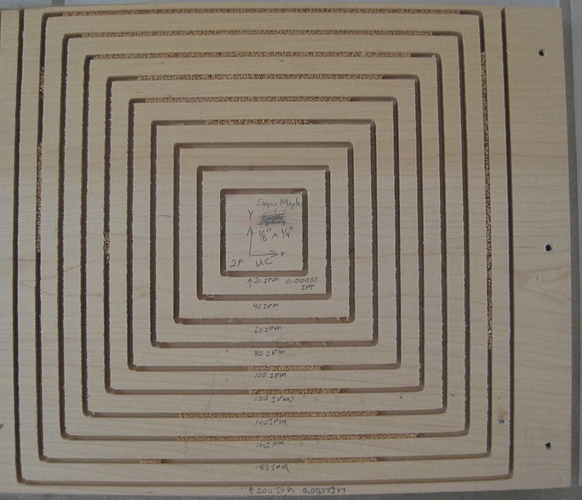
Also remember that the heat is produced by cutting inefficiencies. So, cutting thicker chips requires more power and generates more heat, Thicker chip are also harder to clear as shown below. Single pass 1/8" wide X 1/4" deep slots were cut in sugar maple with a 2 flute upcut endmill at 27,000 RPM at feeds from 20 IPM (0.00037 IPT) to 200 IPM (0.0037 IPT) on a Shapeoko XXL with Dewalt DWP611. Some of the bigger chips were dug out, none of them fall out.


" I’d love to see someone work up a full physics simulation of a cut which would accept:

  • material characteristics
  • endmill characteristics
  • spindle settings
  • G-Code toolpath

and which would spit out a count of:

  • volume of material removed
  • approx. # of chips generated and their size / shape
  • required power input for the spindle
  • greatest forces exerted against work-holding and the direction(s)
  • temperature range of chips
  • heat imparted on the uncut stock

For bonus points, it would analyze the toolpath and adjust feed rate, and spindle rate to optimize the cut."

Tried this? 2019-08-15a Speeds and Feeds Workbook.zip (155.7 KB)
1 Like

The edge bevel on every endmill and drill that I’ve seen is on the outer edge. Wouldn’t that be a more likely source of heating than the microscopic inner edge? With thermally conductive workpieces, wouldn’t more of the heat flow into the relatively cool, massive, and low resistance workpiece and endmill/spindle than into the chip? Doesn’t your Harvey link say " In materials like titanium that don’t transfer heat well, proper coolant usage can prevent the material from overheating."

I’m anxious to read your second reference - thanks for that link. But it does say: “A considerable amount of heat generated during machining is transferred into the cutting tool and work piece, thus the contact length between the tool and the chip affects cutting conditions and performance of the tool.” Its talking about metals though! :slightly_smiling_face:

One last(?) question. Do you still contend that most of the heat generated when milling plastics goes into the chip and that high chiploads are necessary because of that? :thinking:

Don’t know if it’s been mentioned or asked, but on this 1/8" end mill how long is the actual cutting length? The C3D #102 .125" Flat Cutter has a cutting edge of 1/2" I believe. To be cutting 1/2" material you’re right at the edge of that length and running out of room to evacuate chips. The speeds and feeds are off as has already been mentioned, but you might also look at something like a single flute 1/4" bit instead of the 1/8" bit.

Dan

4 Likes

@DanoInTx This is an excellent point !

1 Like

Quick response-- qualifying a code build and even at 5% speed, the machine will do a lot of damage quickly…

Outer edge? Inner edge? Do you mean the clearance angle? That is needed to prevent rubbing. Too much feed per tooth and this will rub on the stock (you may have experienced this trying to force a twist drill too fast). Otherwise, this is not a “source of heat”…

Some heat will get into the workpiece. But most ends up in the chip. A considerably amount does not mean most of the heat, only that you can’t ignore it (barring running the tool very, very wrong).

For practical purposes, ALL of the work done by the tool goes to heat at the tool (an insignificant amount becomes kinetic energy moving the chips), either from friction or deformation/fracture of material. It has nothing to do with efficiency.

Heavy chips are not necessary due to the heat going into the chip. Too light a feed will give rubbing due to material deflection, and with most plastics, this is a moderate feed, as they are quite elastic, compared to, say, steel. Rubbing heats the base material and tool. This has a number of unpleasant results, including melting of the material. Too light of a feed tends to give fine chips that pack and jam in the flutes and melt in easily. Under similar heat, heavier chips tend to clear better, within reason.

No where do I say or imply that high chip loads are necessary because most of the heat (under reasonable cutting conditions) ends up in the chip. I did say that you need sufficient chip thickness for them to clear and for consistant cutting without rubbing.

If this discussion had included forced cooling and chip evacuation (liquid or gas), other things would have come in, but it did not. You don’t need to LIKE that, in the situation under discussion, most of the heat should go with the chip (I will elaborate: with the ductile and malleable materials being discussed), but that is what it is.

I’ll leave it at this.

1 Like

Violating one of the most basic principles of thermodynamics? Woodworkers (@WillAdams and others), have you ever seen or heard of chips/sawdust burning, scorching, or catching fire on anything other than an improperly operated CNC machine? Have you ever seen or heard of the workpieces being scorched?

Here’s what I meant by outer and inner cutting edges. Notice how much more friction inducing cutting area engagement occurs on the outer edge than the inner edge.

“For practical purposes, ALL of the work done by the tool goes to heat at the tool (an insignificant amount becomes kinetic energy moving the chips), either from friction or deformation/fracture of material. It has nothing to do with efficiency.” I suspect that, with most if not all materials, most of the work goes into fracturing the material. But do agree that an insignificant amount goes into kinetic energy moving the chips. Unfortunately, fracturing the material can be an inefficient process, so heat is generated.

“No where do I say or imply that high chip loads are necessary because most of the heat (under reasonable cutting conditions) ends up in the chip.” Sorry, I guess I misinterpreted your intended contribution to this discussion!

" You don’t need to LIKE that, in the situation under discussion, most of the heat should go with the chip (I will elaborate: with the ductile and malleable materials being discussed), but that is what it is.

I’ll leave it at this."

For me, its really not a matter of “LIKE”, I’m just trying to understand your point of view. :slightly_smiling_face:

@Julien, @Vince.Fab
The proof is in the pudding. Why not use your IR cameras to determine what really happens?

1 Like

Agreed, it’s only when things go wrong that there is melting or fire or smoke.

My understanding is this:

  • endmill and stock start out at ambient temperature
  • as cutting occurs, friction between the endmill and the stock/chip EDIT: and chip deformation as noted by @The_real_janderson creates heat
  • this heat is divided between the chip and the stock and the endmill in accordance with the characteristics of each EDIT: or formed in the chip and the stock
  • some cooling happens as the endmill edge leaves the stock material and spins in open air
  • if/once the endmill heats up beyond ambient temperature it then has additional thermal energy which presumably is transferred into the stock or the chip, shed into the atmosphere, or retained in the endmill (EDIT: with some being transferred into the collet and the body of the spindle/trim router)

I think that covers everything (corrections/additions welcome) — I’d love to see the physics of it all written out as mathematics which we can examine and verify.

2 Likes

I recently bought one of these from Amazon to cut thick Baltic birch. It’s a 1/8" diameter 2 flute endmill with a 1" cutter height. It requires 1/2 the MRR, power, and force that a 1/4" endmill would require for cutting. Lonnie (if still online?) should minimize cutter stick-out though! Maybe the primary problem (OP) is that the bottom 1/32" of the endmill being used is worn out?

Some heat will be conducted into the collet and spindle armature too.

1 Like

Note that it’s not only BW who advocates thick chips in plastics, I just stumbled upon this Onsrud site, they recommend for a chipload of 0.004" to 0.012" when milling plastics without coolant.

I have tried HARD to follow the different positions stated above, and I am certainly not in a good position to argue one way or the other, but if I take a step back from the details what I hear is that friction and deformation are causing heat (nobody disagrees here right?), heat needs to go somewhere, some of it in the chip and some of it in the workpiece, but anyway the surface layer is just a lot of future chips, so in the end what matters is how fast one can get hot material out of the way, be it with lots of very thin chips or fewer thicker ones. @WillAdams told it better than I just did though.

1 Like

So that really was BW? Are you sure that they’re not the maximum recommended chip loads like their other chipload charts. I can’t get past the following page, what am I missing?

OK, here’s what I found at “In plastic, there is a very narrow range of chipload to maximize finish and cycle time. Since finish seems to be one of the most important factors in machining plastic, the range falls between .004 and .012. However, finish is always a personal decision and some applications may warrant a larger chipload at the expense of finish to increase productivity. In other words, do not be limited by the recommended range, but use it as a guide.”

1 Like

yes, sorry I forgot to post the link to the actual page, it’s the “the Router way” document in this section

EDIT: I meant this pic and text specifically:

2 Likes

Cool -thanks! Here’s some more of the textChip Load
Once the correct tool geometry is chosen, the proper chip load is the next consideration. In mechanical-plastics machining, the recommended chip load range is 0.004 to 0.012 ipt, which results in an excellent finish and acceptable productivity rates (Figure 3). This narrow range imparts the finest finish through the continuous generation of properly sized or curled chips. Inadequate chip load can lead to knife marks, which adversely affect the finish. O-flute tools with a high rake and low clearance help eliminate knife marks by slightly rubbing the part during machining."
Sounds like friction on the outer cutting edge bevel is used to melt/smooth the workpiece with their specialized endmills. Acrylic cuts real nicely with a laser too!


Could it be that some manufacturers only provide cutting recommendations because they’re designed for that particular speed? The 1/8” endmill recommendations would result in feeds of 50- 75 IPM, cutting forces of ~3.2 - 4.7 lbf, cutting powers of ~ 29 - 44 Watts, and MRRs of ~0.78 - 1.17 cuin/min. Doubling the speed to 25,000 RPM would enable a doubling of the feed rates and MRRs while maintaining the same forces and cutting powers. Halving the chiploads by reducing the feedrates to 50 - 75 IPM at 25,000 RPM would reduce the recommendation’s cutting forces and powers by a factor of 2.

1 Like

[quote=“Julien, post:28, topic:15778”]
what I hear is that friction and deformation are causing heat (nobody disagrees here right?), heat needs to go somewhere, some of it in the chip and some of it in the workpiece, but anyway the surface layer is just a lot of future chips, so in the end what matters is how fast one can get hot material out of the way, be it with lots of very thin chips or fewer thicker ones. @WillAdams told it better than I just did though [/quote]

IMO the best way to cut acrylic is to minimize heat generation by minimizing chiploads (unless something like Aluminum HSMing occurs.) Since the melting temperature of acrylic is much lower than Aluminum, any HSMing would occur at a much lower endmill temperature.

It appears that early on in this discussion BW wisely gave up on his “deformation” argument. All of the heat is caused by friction. It tries to melt the cut edges but virtually none of it is conducted (goes) into the plastic. Any residual heat will be conducted into the endmill. Here’s plastic experts’ recommendations for cutting/routing acrylic. “The spindle speed required to produce a satisfactory edge is 10,000 to 20,000 rpm. A smooth, constant feed rate of 10 to 25 feet per minute is required to prevent localized heat buildup, which will cause smearing or gumming of the cut edge.”

This corresponds to 120 to 300ipm, make that 200ipm max on the Shapeoko. They do not explicitly specify number of flutes, but they advise 2 fluted tools so let’s assume that. This gives a min chipload of 120 / (2 x 20.000) = 0.003", and max of 200/(2x10.000) = 0.01", so relatively thick chips and quite in line with earlier discussions and with Onsrud [0.004" to 0.012"] recommended range ?

I don’t disagree that the theory calls for lower friction to get lower heat and that thin chips are a way to get that, but many, many people have experienced good cuts in plastics with thick chips, as long as one is feeding fast enough. Maybe the chipload does not matter so much as the fact to get that tool moving out of there, fast?