Cutting Thick Acrylic

I have cut .125 and .25 with no real issues, however when I tried .5 I did see some strange things.

  1. The .125 bit seemed to be pushing a wave ahead of it as it traveled the course. I later determined that that was molten plastic.

I have the speed set to the default that CC suggested an the spindle speed on my dewalt set to 4. Travel speed seems slower than wood.

Any advice to make clean not molted cuts?

Shpeoko 3
Dewalt router
.125 box end bit

Thanks

1 Like

Can you post the feedrate that you used / that CC recommended ? RPM at 4 on a dewalt is very fast, there is 99% chance that you are not feeding fast enough which would explain the melting
What’s a “box end bit” ?

EDIT: assuming you are using a 1/8" 2-flute square endmill (e.g. #102), at setting 4 (~21500 RPM) I would aim for a chipload of about 0.002", and you would get that with a feedrate of 86ipm. I would also start with a depth of cut of .06" and then increase it up to .125" if it works fine. Also, make sure your endmill is SHARP, that is important always but especially in plastics.

EDIT2: I realize I did not address the thickness topic. If you are doing a profile cut, I suspect your problem may also be chip evacuation. You might get away with it at .125 and .25, but .5 is deep for a slot, maybe chips cannot get out efficiently enough, get in the way of the cutter, which ends up in heat and melting. You could try using a jet of compressed air aimed at the tool, or using an O-flute endmill that is the best tool anyway for cutting plastics (since it allows lower feedrate for agiven chipload, and provides much better chip evacuation)

3 Likes

Here are the settings I used. I nhave several ideas I can try. All time comsuming and step intensive but I would like to hear your ideas

1 Like

Thanks for posting this info. So incorrect feedrate is definitely your problem: CC recommended a spindle speed of 9375 (which is not even achievable on a Makita router, let alone a Dewalt router, I wish CC did not do that to users…), but by setting your Dewalt on 4, you actually had a spindle speed of 21500RPM, more than twice more than intended. And the CC recommendation was borderline too slow in the first place (19.5ipm at 9375RPM with a 2 flute endmill is 0.001" chipload, which really is the lower limit for cutting plastics). By running your job at 21500 RPM and 19.5ipm with the #102, you had a chipload of 0.0004" chipload, and that is definitely too small.

The remedy is to feed faster, to get back into 0.001" chipload territory. There’s a simple rule you can apply, that if you cannot reach the RPM setting CC is recommending, just multiply BOTH the spindle speed and feedrate by a given factor, and this will maintain the same chipload.

So in your case, assuming you stay at speed 4 on the Dewalt, the RPM “correction factor” is 21500 (actual RPM) over 9375 (intended RPM), that’s 2.29. You then need to increase the feed rate value in CC by at least that, so 2.29 * 19.5 ~ 45 ipm. That should work (at least much, much better than running at 19.5ipm, but if I were you, and considering your shallow depth of cut (0.03’’), I would push that to x2 the feedrate that CC recommends, to get a chipload of 0.002’’. And that’s how you end up with the ~90ipm value I was recommending in the earlier post.

So long story short : only modify feed rate from 19.5 to 45 in your project, and rerun. If the cut is still not perfectly clean and/or your are not getting nice snowy chips, increase feedrate again (keeping everything else the same), up to 90ipm if that is what it takes.

8 Likes

I’m glad Julien is here preaching about the benefits of thinking in chip per tooth!

2 Likes

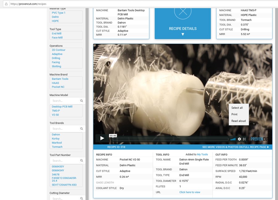
How did you determine that (smaller chips are easier to clear)? One of the free “ProvenCut recipes” shows HSM(?) for Delrin (acetal) - thanks @Vince.Fab! :slightly_smiling_face:

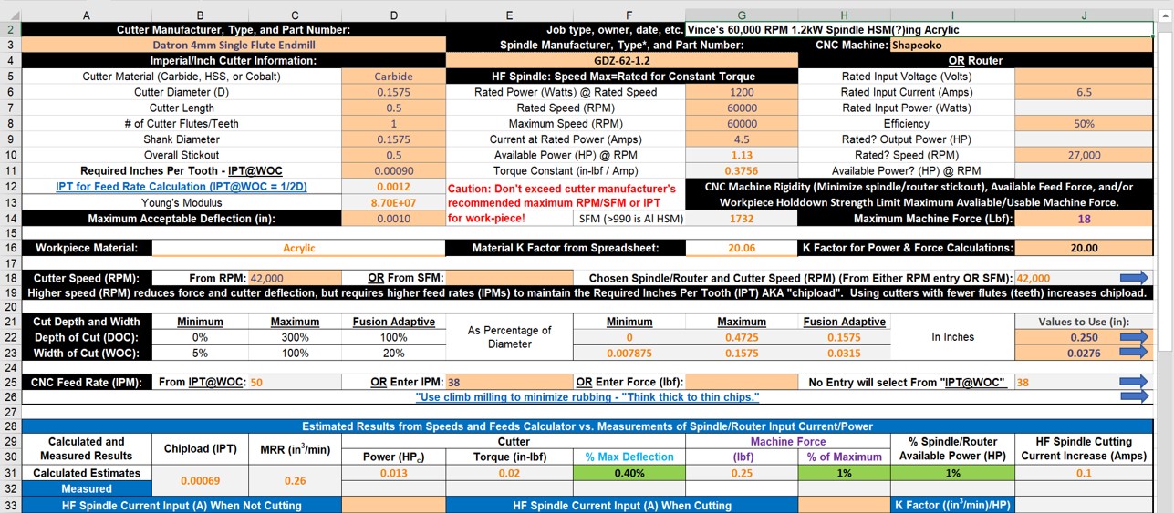
As shown below, the actual chipload (after compensating for chip thinning) was 0.00069".

2 Likes

Well it seems to me that anything below 0.001" is in the danger zone. Sure, with a perfectly sharp cutter and using a toolpath that is easy on the cutter and on chip evacuation, you could probably make it work. But I assumed that Lonnie is doing deep (0.5’') profile cuts, hence poor chip evacuation especially with this small 2 flute cutter, and may not use a fresh cutter either, so why take the risk of running such a low chipload? (and in this specific case, it’s not a risk anymore, it’s an actual problem of rubbing and melting)

This ProvenCut example has a chipload that is 50% larger, uses an O-flute (better chip evac) and an adaptive toolpath with 17% stepover (plenty of space for chip evac too), so it’s fair as an example that a chipload below 0.001" can work, but I don’t think it’s fair to compare it to a (probable) slotting cut with a 2 flute endmill?

Anyway, I hope we will not confuse Lonnie by discussing these chipload subtleties, and I’m looking forward to hearing about what happens to the cut when feedrate is increased, or another remedy to the melting is found ! :slight_smile:

1 Like

Some cutters live in that danger zone


IMO, assuming his/her endmill is in decent shape, Lonnie’s problem is the more likely the result of inadequate feed rate than insufficient chipload. But, it does help point out how messed up CC’s speeds and feeds recommendations are! Lonnie should really be using at least a 0.125" DOC (rather than 0.029")!

@The_real_janderson

“I’m glad Julien is here preaching about the benefits of thinking in chip per tooth!”

Can you please explain why?

Several reasons:

The tool needs to cut, not rub. On materials that have a lot of give, like acrylic, too light a chip leads to rubbing, due to material flex, making heat, rather than cutting, making less heat, much of which is removed with the chip. If you have ever tried to drill through arcylic with a twist drill, you have likely seen the same issue: insufficient feed in thin material give a drasticly undersized hole (the material flexes under the bit, and springs back behind the cutting edge) and leads to the tool being covered in melt, or worse, getting stuck, in thicker material.

The thickness of the chip controls how well the chips clear and remove heat. Too thin, they tend to pack and hold the heat in the tool. Too thick, the individual chips jam up. (<-- really oversimplified) Ideal is a chip thick enough to have structure that clears the tool easily, taking the heat away with it, either as a curl or by breaking into small segments that are still large enough to clear the flutes without packing. With milling cutters, you don’t generally get the “long curley” that a drill bit gives, but in any situation where there isn’t a good way for the chips to clear (profiling the outside of a part lets the chips clear easily, slotting is the worst case for no clearing space other than lifting by the flutes of the tool. and is often worse than drilling due to packing behind the tool), the chip thickness and form needs to be controlled. The concept is independent of material.

There is a lot more, but this is about my limit at this hour.

4 Likes

BW? How does something with virtually no thermal conductivity " do that? :thinking:

I cut .5" clear acrylic often. Single flute (O flute) is the answer. As a matter of fact, it’s the answer for a lot of things. I usually cut around 12k and 40ipm with conservative doc (.06", .13" depending on cutter dia.). Take a full depth finishing pass on the last cut to get clean edges. :wink:

3 Likes

Why did you chose to do it this way? :thinking:

There will be heat produced in cutting. Much of it is in the chip. If the chips clear well, the heat goes with them. .

The low thermal conductivity has little to do with it. If anything, the low thermal conductivity makes the situation worse, as the chips don’t readily lose heat to the surrounding material and get soft and sticky. They need not melt to foul the tool. If they clear well, then it matters not if they are soft and sticky.

2 Likes

Because I get good results.

3 Likes

Isn’t the heat produced at the cutter - workpiece interface? How does “much of it” get into the chip (even with workpieces like aluminum that have high thermal conductivity)? :thinking:

The heat should be split between the chip and the material (EDIT: but as @gmack noted below, due to thermal inefficiencies and the difference in heat absorption/conductivity isn’t) — the thing is, the material will then get cut again, so heat in it will either be in the next chip, or left in the stock — so it is possible for a chip which has two cut surfaces (the exposed surface, and the newly cut one) to have twice as much heat as one might initially expect.

I’d love to see someone work up a full physics simulation of a cut which would accept:

  • material characteristics
  • endmill characteristics
  • spindle settings
  • G-Code toolpath

and which would spit out a count of:

  • volume of material removed
  • approx. # of chips generated and their size / shape
  • required power input for the spindle
  • greatest forces exerted against work-holding and the direction(s)
  • temperature range of chips
  • heat imparted on the uncut stock

For bonus points, it would analyze the toolpath and adjust feed rate, and spindle rate to optimize the cut.

2 Likes

Short answer (which is getting to the depth of my knowledge)

There are a number of ways heat is produced (different sources break this down in slightly different ways):

Friction between the cutter and the base material
Friction between the cutter and the chip
Work done to the chip deforming it, and work done to deform the material ahead of the cutting edge (the shear zone)
Work done to actually separate the chip from the base material

There isn’t a lot of rubbing between the tool and base material (ideally) when actually cutting. Contact is limited to the cutting edge. This is not the major source.

There IS a lot of rubbing between the chip and the tool, as the chip rides the surface for some distance from the point where the cutting edge separates it from the base material.

The chip is generally deformed a fair bit. Depending on the material, this may be mostly bending of the chip at and after separation, or a lot of crushing in the shear zone just ahead of the cutting edge. If you look at macro films of tools cutting metal, you see this. This is a big heat source. Even most of the heat generated ahead of the cutting edge goes with the chip, since the material that will become the chip gets most of the work done to it and there is little time for heat to flow into the base material.

Note that the heat sources tend toward putting more heat into the chip than the base material. Friction will also heat the tool. Without active cooling, the tool doesn’t get rid of much heat (by conduction to the toolholding, by conduction to the base material and/or chips, by radiation, and by convection. If it gets hot enough for radiation to be significant, there is a real problem. Thermal radiation is a a function of the fourth power of temperature, which means, for our purposes, think incandescent before radiation is significant.) This is one reason coatings help so much with tool life-- lower friction. They also help prevent material sticking to the tool (which is real bad mojo for tool life)

Several references:


https://www.chipblaster.com/explanation-of-heat-in-cutting

3 Likes

Don’t forget that carbide endmills, unlike plastic, are good thermal conductors and heat takes the path of least resistance. Heat typically spreads radially outward from its source in conductors but not in insulators (because it can’t.)

Also remember that the heat is produced by cutting inefficiencies. So, cutting thicker chips requires more power and generates more heat, Thicker chip are also harder to clear as shown below. Single pass 1/8" wide X 1/4" deep slots were cut in sugar maple with a 2 flute upcut endmill at 27,000 RPM at feeds from 20 IPM (0.00037 IPT) to 200 IPM (0.0037 IPT) on a Shapeoko XXL with Dewalt DWP611. Some of the bigger chips were dug out, none of them fall out.


" I’d love to see someone work up a full physics simulation of a cut which would accept:

  • material characteristics
  • endmill characteristics
  • spindle settings
  • G-Code toolpath

and which would spit out a count of:

  • volume of material removed
  • approx. # of chips generated and their size / shape
  • required power input for the spindle
  • greatest forces exerted against work-holding and the direction(s)
  • temperature range of chips
  • heat imparted on the uncut stock

For bonus points, it would analyze the toolpath and adjust feed rate, and spindle rate to optimize the cut."

Tried this? 2019-08-15a Speeds and Feeds Workbook.zip (155.7 KB)

1 Like

The edge bevel on every endmill and drill that I’ve seen is on the outer edge. Wouldn’t that be a more likely source of heating than the microscopic inner edge? With thermally conductive workpieces, wouldn’t more of the heat flow into the relatively cool, massive, and low resistance workpiece and endmill/spindle than into the chip? Doesn’t your Harvey link say " In materials like titanium that don’t transfer heat well, proper coolant usage can prevent the material from overheating."

I’m anxious to read your second reference - thanks for that link. But it does say: “A considerable amount of heat generated during machining is transferred into the cutting tool and work piece, thus the contact length between the tool and the chip affects cutting conditions and performance of the tool.” Its talking about metals though! :slightly_smiling_face:

One last(?) question. Do you still contend that most of the heat generated when milling plastics goes into the chip and that high chiploads are necessary because of that? :thinking: