Probably the problems are pen deflection and possibly uneven wasteboard — I’d suggest making some clamps, then a “real” project
When I tightened mine the instructions were a little different. I got one side tight then I setup the opposite side such that the screw would just barely contact the threads of the clip. Tightening it from there seemed to give it the right amount of tension.
What I see there is the left/right (X) movement seems okay but the top/bottom (Y) movement doesn’t. That’s why I said double check the Y axis set screws on both sides. Might even just want to loosen them and re-set them even if they look okay.
I decided to do another test cut after making adjustments. The other day, I had tried one of the sample files from VCarve, the “Avalon” name plate. It did not go well. After making adjustments yesterday and today (based on advice from all of you nice folk), I did the test again. The first attempt is on top, and the latest attempt is below. As you can see, the result is still not quite perfect, but it is MUCH better that the original attempt.
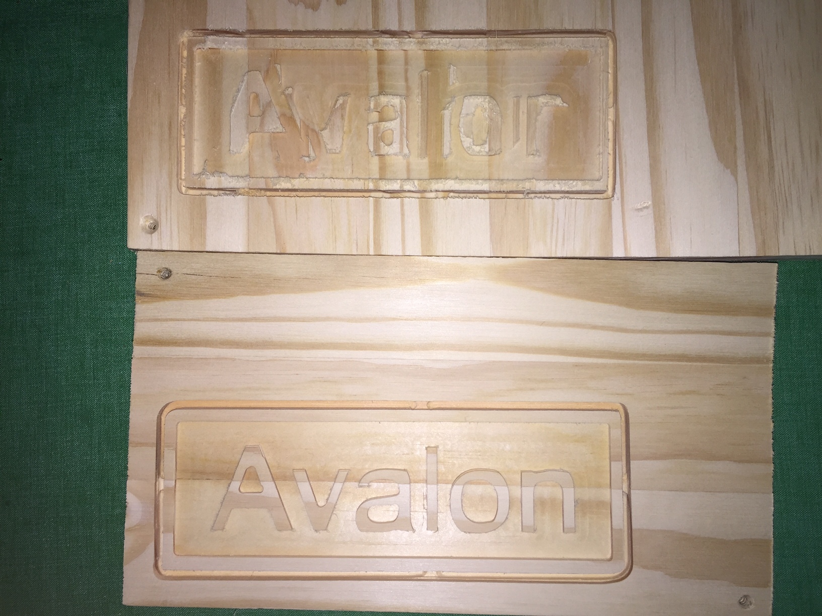
I’ll keep plugging away. I just need to learn what needs to be adjusted based upon what is not cutting correctly.
Thanks again for all the advice.
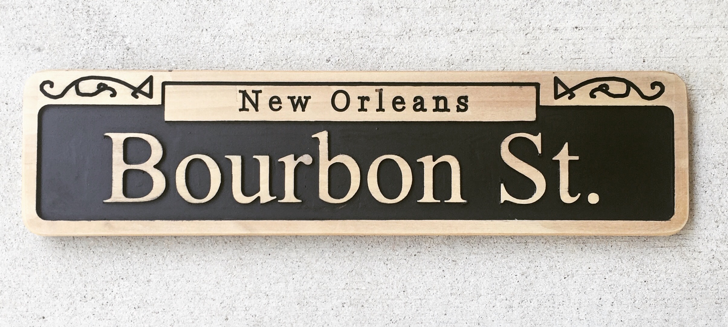
You’re right. It should look like this. (ignore the squiggly lines, that is programmer error…me)
Are you 100% sure all the screws and belts are set correctly?
Tom, you’d figure that C3D would use Locktite on ALL Screws .or Set Screws when they install the units together! I would consider this when I dive in and make my own purchase (hopefully later in the year).
Michael
Greg, your one up on me here! You have a unit in front of you, I don’t… So… let’s take what I’ll share with a grain of salt until it can be verified by others here.
In the center spindle in the picture mentioned, at the bottom of the spindle sticking up through the hole of the pulley, you may notice a flat side to the center motor shaft. I think this is where your SET SCREW should be sitting on (the POINT of the Set Screw, that is).
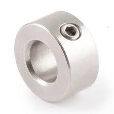
First Pic: a Set Screw sitting in your Collar.
Second Pic: Red Line pointing to the center shaft FLAT where your Set Screw should sit on!
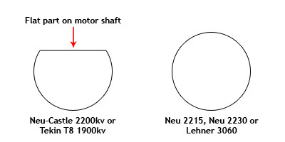
If your Set Screw is NOT sitting on the FLAT Side, Bad things happen (Gremlins).
Hope this helps!
NOTE: Pictures quickly grabbed via Google Images, and are NOT my own pictures! Just used for demonstration purposes only.
Michael
1 Like
Michael – Thanks to info I got from other people on the forum, I did get the set screw situation figured out. However, the pictures you supplied were awesome and really make things clear! I wish I had had them three days ago!
Rich - Thanks for your advice. I’m pretty sure all the belts are tight now. I’m going to double check all the screws. Edward Ford gave me some advice via the support e-mail about checking to make sure the v-wheels are tight.
I don’t have as much time now that the long weekend is over, but I’ll post an update for everyone once I get a chance to make more adjustments.
Thanks again for everyone’s time.
1 Like
This morning, I checked over the machine and believe that I found one of the v-wheels on the X axis a bit loose and there was a little give. I tightened that up, and ran two more tests.
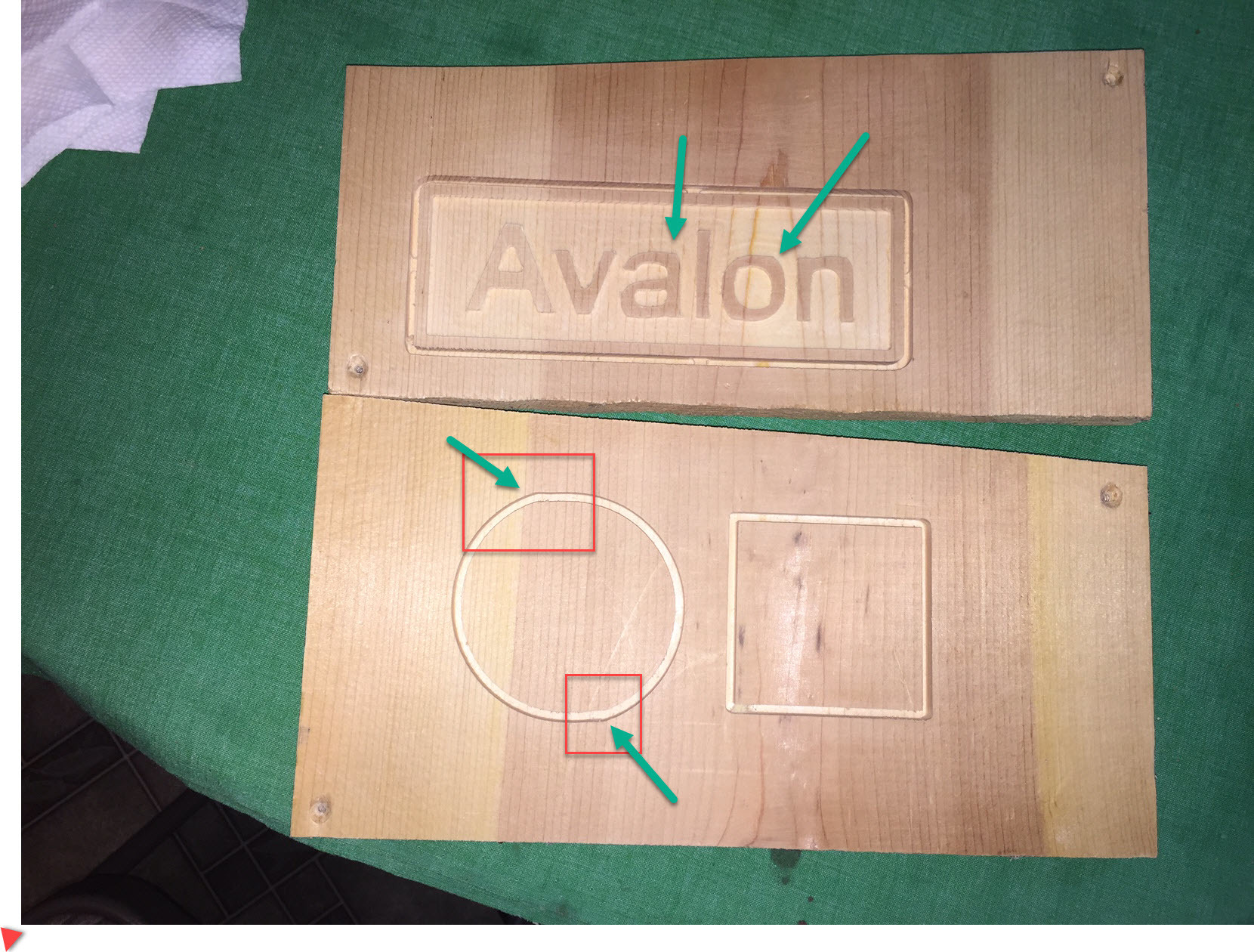
As I point out in the picture, there are two “bumps” in the top left and bottom right of the circle. Measuring with calipers, the width of the circle is 2.8660 inches and the height is 2.8150 inches.
The height of the square is 2.4225 inches and the width is 2.4870 inches.
Things continue to improve some, but does anyone have any suggestions on adjustments based on the picture? Or does anyone recommend a different test file to use that might provide better information for diagnosis?
Thanks,
Greg
This is a post I made when I was trying to dial my machine in. It worked well for me. Check it out and see if it works for you.
Likely backlash.
we have two pages on this sort of thing on the wiki:
- http://www.shapeoko.com/wiki/index.php/Operation_Troubleshooting
- http://www.shapeoko.com/wiki/index.php/Tuning
In a lot of ways, it’s a tension system like a bolt and nut:
- pulleys have to be tight on shafts – check Set screws
- belts must have sufficient tension to hold things in place – Y-axis belts should have even tension
- V-wheels must be tight enough to hold things in alignment but rotate smoothly to allow motion
- wiring has to have continuity
Catalin’s suggestion of pushing and pulling on the collet nut and noting where the mechanism a low movement is a basic one.
Similarly, jog the machine and note when it fails to move as it ought
Regarding Will’s suggestion to “jog the machine and note when it fails to move as it ought”… Since I’m a newbie and never used a machine before, I’m not sure how it should move. When I use the “fast” job feature in Carbide Motion, both the X and Y movements will go about 3 seconds, then there is a slight hesitation, and then they move again. I made a short video. Here is a link that will be good for about 30 days:
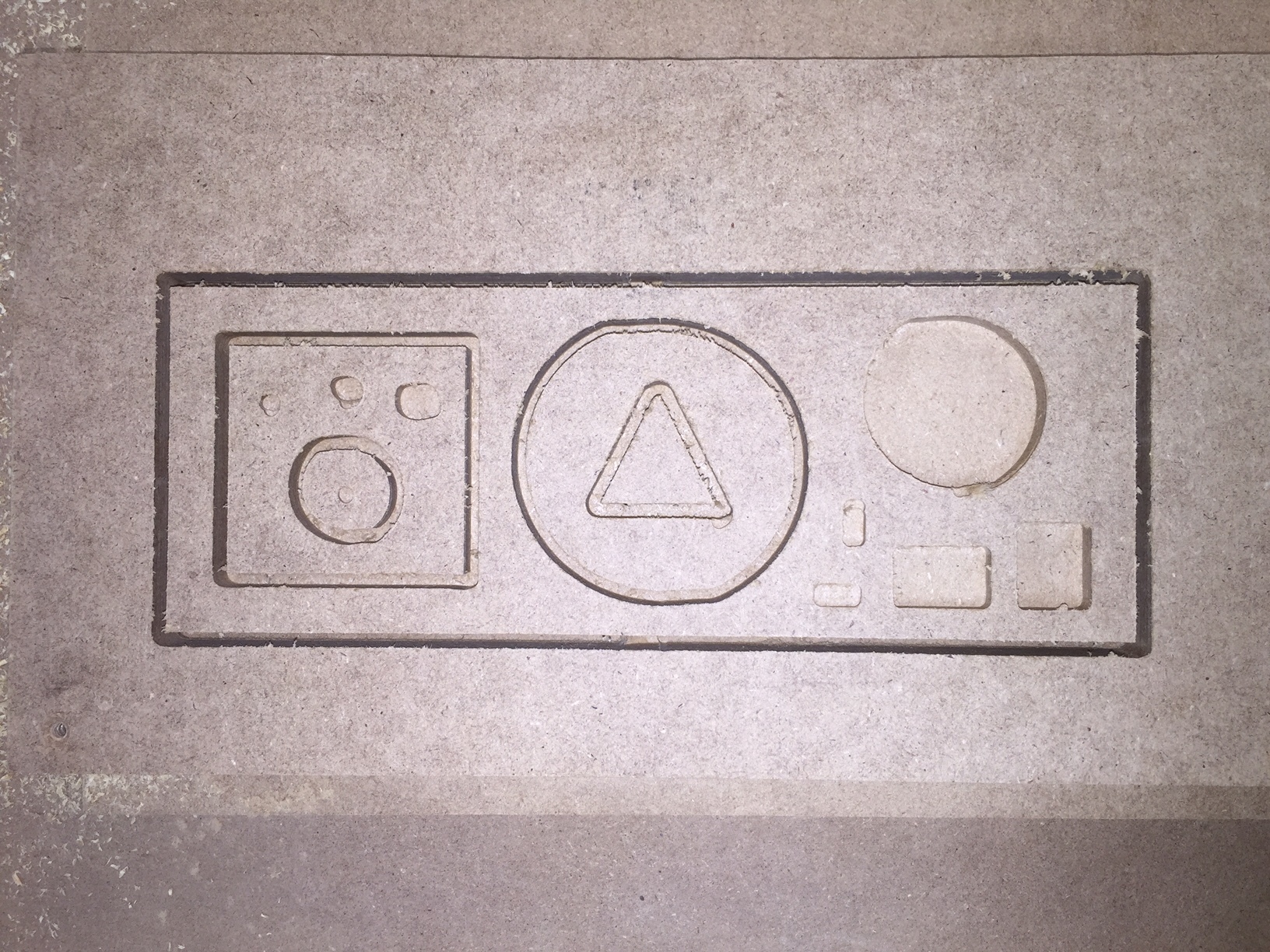
I also downloaded the calibration file that Stacy Boncheff recommended. I was able to get it converted into gcode. Here is a picture of how it turned out:
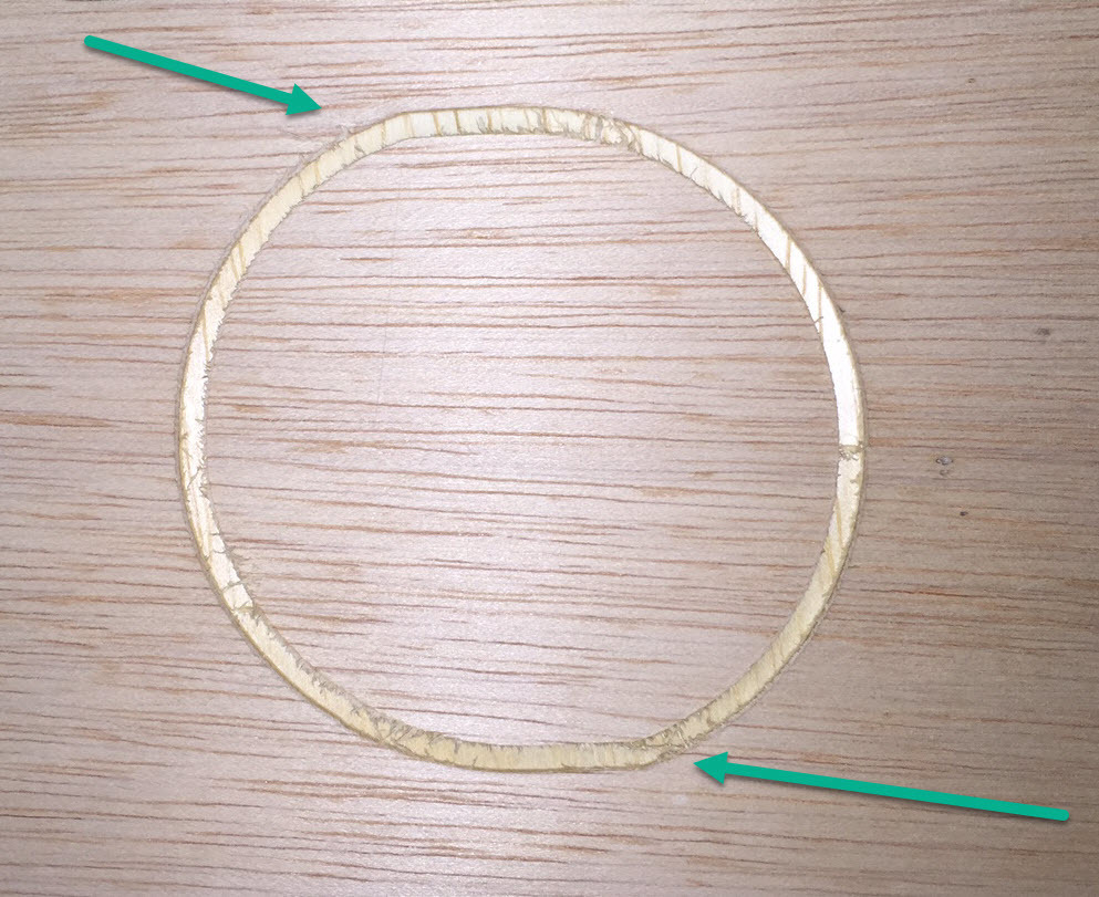
Still having issues with circles. Not sure how to tell if it is an X or Y axis problem or a little bit of both…
Looks like backlash — probably from a set screw which seems tight, but isn’t in contact w/ the shaft.
I’d bet good money that one of the !$@^%#^ set screws isn’t tight against the flat of the shaft.
I had all sorts of weird gremlins until I figured out that the preassembled carriages had set screws that were tight but not against the flat, making the machine kinda sorta work right mostly except when it didn’t.
In fact I’ll bet it is the x-axis set screw.
OK. I’ll take a closer look at the set screws again. I’ll be out of town this week, so I won’t get to look at it till next Saturday. I just didn’t want people to think I was ignoring the replies. Thanks for the suggestions and I’ll let you know what I find…
Judging on how long this simple fix has taken…I think I’m going to drive over to his house and do the 2 minute fix myself.
1 Like
Sorry you keep getting sent back to check the screws but it’s just the most likely cause. Loosen both, rotate the geared piece until one is perfectly lined up with the flat spot, tighten that one. Tighten the other until snug (it’s not on the flat so it’s less important but don’t want it falling out)
2 Likes
Rich and Dan,
I work full time, so I don’t get many chances other than the weekend to try and work with things. I had already adjusted the set screws (or so I thought), but I will be taking a look again. Have to head out of town for business this week, but I’ll be back on Friday. If I still don’t make any progress, I’ll post my address and wait for Rich to show up!
3 Likes
Shapeoko party at Gregs 
2 Likes
OK. Back from out of town. I took off the X-axis motor. It looked like the set screw was lined up with the flat, but it may have been off just a millimeter or so. I loosened it, made sure it was lined up, and tightened it up. Made sure the other set screw was also tight. I also checked the set screws on the y-axis motors, and they appeared to be lined up with the flats and tight as well.
So, I ran another test of a circle, and still seem to have the same basic issue. There are areas toward the top left and bottom right that still are just off.
Last weekend, Rich was threatening to drive over to make needed adjustments himself. At this point, I would welcome it. Seriously – is there anyone in the Washington, DC / Northern Virginia area who would be willing to come over and consult? I’d be willing to pay a consulting fee…
Otherwise, I welcome any other suggestions. The stuff I want to work on will involve curves, so until I can get this issue worked out, I’m going to be stuck…
Given that it only happens along the one axis, if the pulley and set screws are okay, my assumption would be loose or bad belt, or loose bolt/nut.
The other thing to check would be V-wheels.
Please try watching the machine and see if you can identify what aspect of it is yielding — I’m almost suspecting a single loose bolt, say for a spindle mount which allows a small shift which is magnified along an angle.