Sometimes pieces might still fit on the machine diagonally but not parallel to x or y.
Does anyone have experience doing this? How do you align the diagonal stock with the cam model?
I could imagine to use the router itself by moving it to specific coordinates, align the stock, set an alignment pin, move to another position and do the same.
Alternatively take scrap wood, set 2 alignment pins, machine the area where the actual piece will be located and put the stock into the machined area. A negative form of the actual piece so to say…
I had some complex shape side panels which I needed to v-carve into which didn’t have horizontal or vertical edges for alignment.
I added 5mm pins around the edges in the CAD model and then bored those holes into the wasteboard, and then put pins in the holes to work as an alignment jig.
I have also used an engraving bit to cut a 1mm deep outline in the wasteboard to help with alignment.
One advantage of using the scrap to cut a part or full negative as a jig to place your piece into is that you can have a square lower left corner to set zero X, Y from too on that jig.
The pins, yes, they were more accurate than the pieces I had marked up and cut with the track saw.
I liked the pins so much that I then ran a CAM program to bore out 8mm pin holes in a grid all over the spoilboard so that I can just stick pegs in to let me line up stock close enough to square without having to indicate.
If you really want to check alignment on a complex shape I find that I can use the Shapeoko as a poor CMM with a v-bit in the collet (not running), zero then jog to location coordinates from CAD and my phone camera on magnify can be used to check to well under 1mm accuracy for marked points or edges.
If you make up a jig which you want to use more than once, you can bore 8mm peg holes straight through the jig into the wasteboard to let you reposition it repeatably.
I have had projects that I would have wanted to put diagonally on my xxl. I guess you could draw the material up with a 45 degree angle and then secure your work but finding the 45 degree reference on the waste board is the rub. Should you use the corner to set the origin has been my problem. The BitZero wont work for an angled work piece but you could use a vee bit to line up on the corner but that is the crux of the problem. Where to line up and set the origin. Plus setting a piece exactly 45 degrees across the waste board is also problematic. Material that sets at 90 degrees to the waste board are easy to line up but any angle other than 90 is the problem. Not sure how to overcome the setup problem. Using a 30x30 inch area the maximum length would be around 42 inches 30squared + 30squared =1800 and square root of 1800 is around 42.xxxx and then depending on how wide your piece is you would need to make it smaller than 42 inches to fit. That would also require you to extend the length off the front of a Shapeoko 3 XXL. So the complexity of setting up off the front and then having unsupported area off the front is adding to the complexity.
This is where I thought one could make a jig with a fixed reference, which is aligned with xy and “transtlates” an alignment to the diagonal.one would just need to include it in modeling
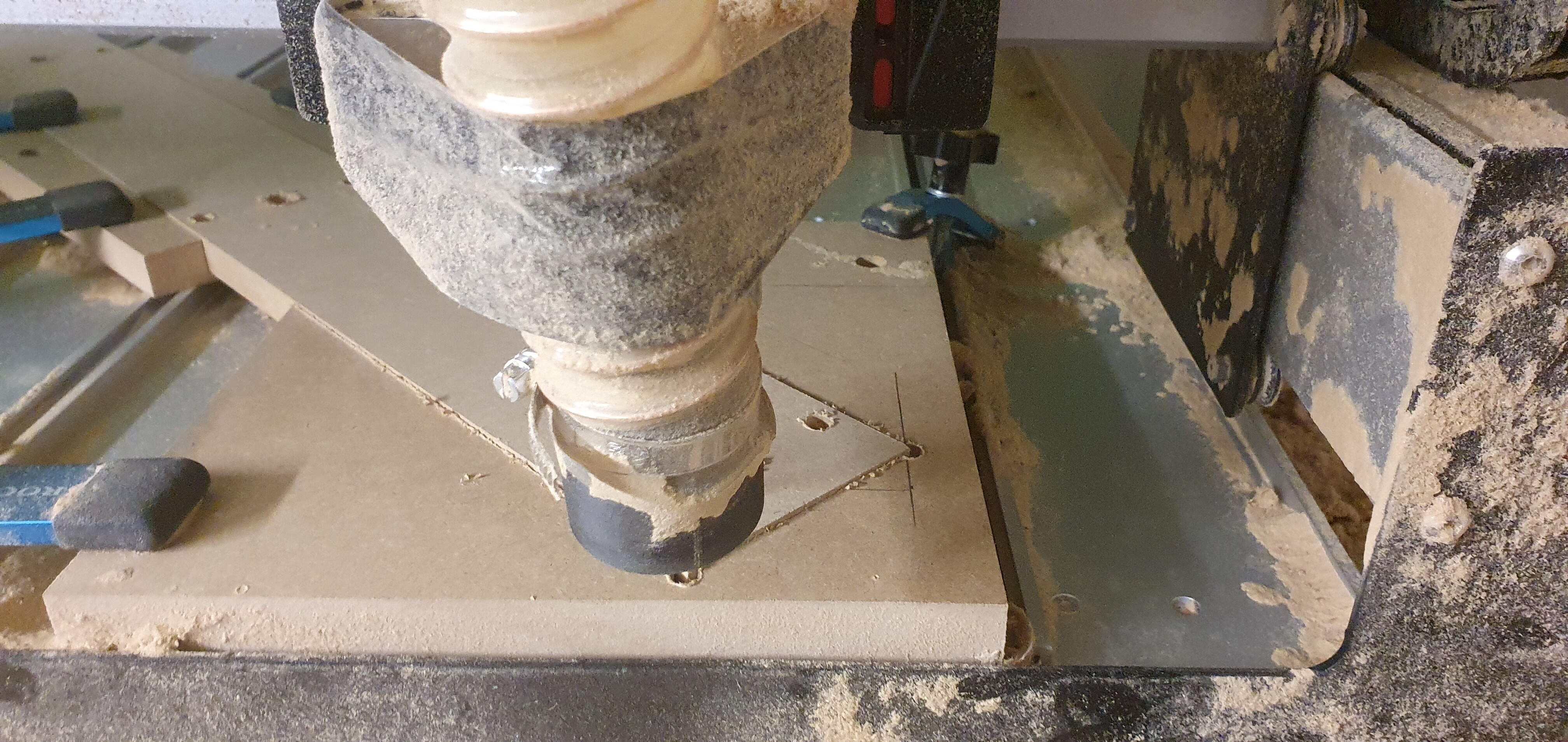
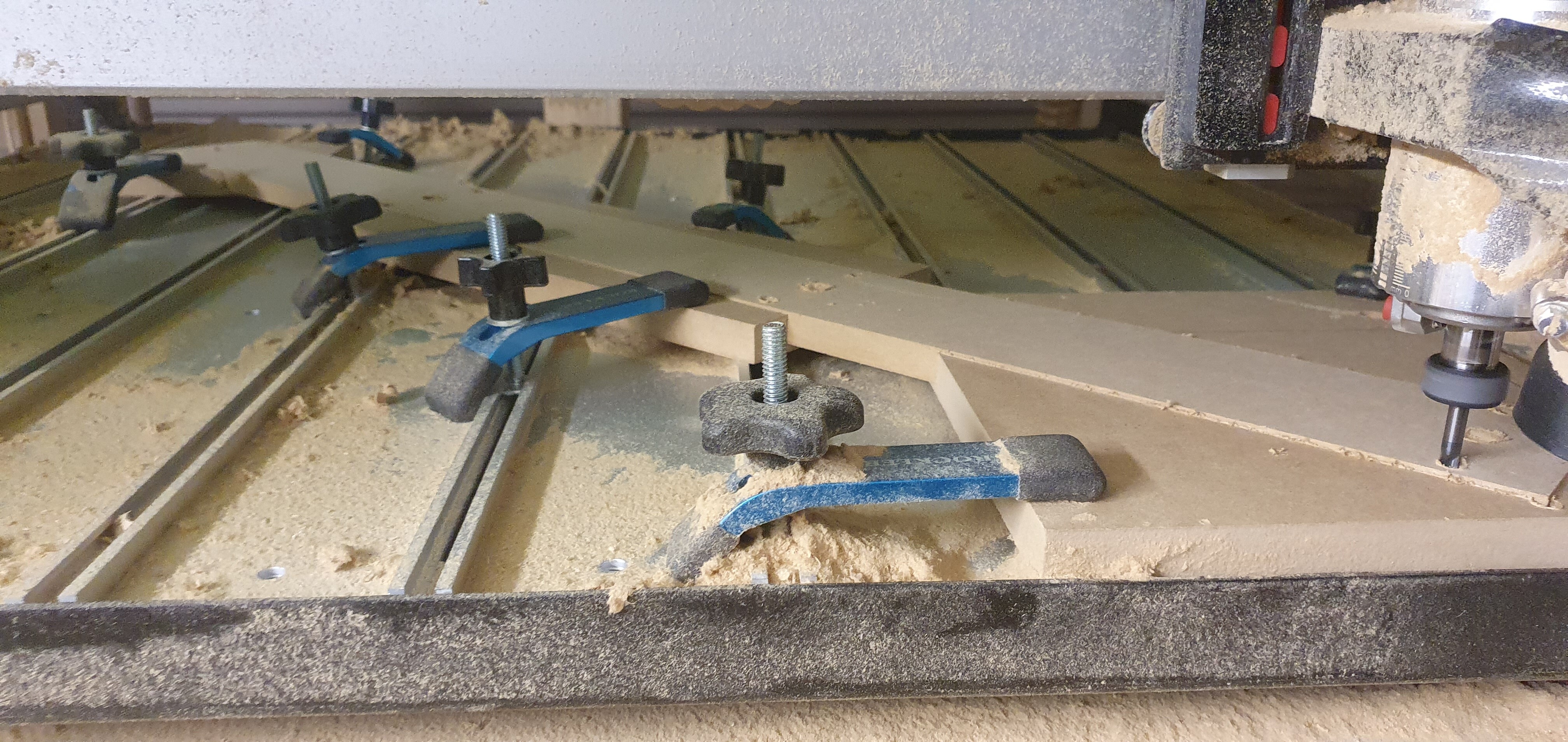
I modeled negatives today, aligned the stock to x/y bottom right and ran the job. This created pockets for my actual stock which was cut to length and width already. Being very careful not to move the negative between cuts, I machined the actual part then.
Part size: 1000x88mm
Result: time consuming, but worked great!
If I’d do it again, I’d take a single negative board instead of 3 separate ones.
It’s easiest to align by setting 0/0, then move the router to the top left position to clamp down the negative boards
Ps: dust shoe was a bit of a problem though, so I had to improvise. MDF is such a nasty dust…